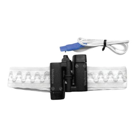
SIMS GRASEBY MR10 Operating manual

0473
Graseby MR10
Neonatal
Respiration
Monitor
Technical Service
Manual

MR10 Technical Service Manual Issue A (April 2001)
SIMS Graseby Ltd. MR10 Neonatal Respiration Monitor
Warnings
Warnings tell you about dangerous conditions, that could lead to death
or serious injury to the user or infant, that can occur if you do not obey
all of the instructions in this manual.
1. WARNING: The MR10 only informs of an apnoea attack, it cannot prevent an
apnoea attack.
2. WARNING: If you suspect that the Monitor is not operating correctly, do not
use and return to SIMS Graseby or a suitably qualified technician for testing.
3. WARNING: Only use the SIMS Graseby Respiration Sensor, REF 0108-0007.
The performance of the Monitor can only be guaranteed with this Sensor.
4. WARNING: The Respiration Sensor should only be used on one infant. Using
the same Sensor on more than one infant increases the risk of cross infection.
5. WARNING: Correct positioning of the Respiration Sensor tubing is important
to avoid the tube becoming entangled around the infant’s neck, resulting in
infant injury or death.
6. WARNING: Mobile communication devices e.g. mobile phones, should not be
used at a distance of less than one metre to the MR10 Monitor, as this could
affect the safe operation of the Monitor. Even if these devices cause no
obvious interference, possible interference can only be ruled out if this advice
is strictly observed.
7. WARNING: The Monitor is not suitable for use with adults or children over the
age of 18 months.
8. WARNING: The Monitor must not be covered by bedding or other objects so
that the audible and visual alarms are impaired. Failure to observe this warning
could result in infant injury or death.
9. WARNING: To prevent the Monitor being accidentally switched off, the Monitor
must not be placed within reach of the infant. Failure to observe this warning
could result in infant injury or death.
10. WARNING: The Monitor must not be pushed into confined spaces, so that
pressure could be exerted upon the keypad buttons causing the Monitor to be
switched off or the settings to be changed. Failure to observe this warning
could result in infant injury or death.
11. WARNING: If the Monitor alarms, before doing anything else make sure that
the infant is safe and comfortable and not in a dangerous situation.
12. WARNING: Use only type LR6 alkaline batteries. Rechargeable batteries are
unsuitable and must not be used as they could affect safe operation of the
Monitor.
13. WARNING: This equipment is not suitable for use in the presence of
flammable anaesthetics oxygen-enriched or explosive atmospheres. The use
of the device in such atmospheres can lead to explosion or fire.
14. WARNING: The Monitor must be operated within the specified parameters, see
Technical specification page 1-11. Failure to do so could result in infant injury
or death.
15. WARNING: With the monitor working correctly, if an alarm occurs frequently
then medical advice must be sought to ensure that the infant’s health is not in
any danger.
16. WARNING: The monitor must not be used in the presence of, or in combination
with Magnetic Resonance Imaging (MRI) machines. Induced current could
cause burns to the infant or user injury and affect the functions of the monitor.
The monitor may also affect the MRI image.
17. WARNING: To avoid possible malfunction of the monitor, do not expose the
monitor to X-rays, gamma rays, ionising radiation, strong electric or magnetic
fields such as diathermy or mobile telephones. Malfunction of the monitor can
cause incorrect monitoring or loss of monitoring resulting in infant injury or
death.

Issue A (April 2001) MR10 Technical Service Manual
SIMS Graseby Ltd.
MR10 Neonatal Respiration Monitor
Cautions
Cautions tell you about dangerous conditions that can occur and cause
damage to the Monitor if you do not obey all of the instructions in this
manual.
1. CAUTION: Refer all service, repair and calibrations only to qualified technical
personnel. Unauthorised modifications to the Monitor must not be carried out.
2. CAUTION: Failure to observe the following cautions may cause internal
damage to the monitor.
•Do not autoclave, steam sterilise, pressure sterilise or gas sterilise this
monitor.
•Do not expose this monitor to temperatures in excess of 40°C (104° F).
•Cleaning Do not immerse the monitor in any liquid.
•Wipe off any liquid spills immediately, do not allow any fluid or residues to
remain on the monitor.
•Do not use abrasive agents or strong organic solvents.
3. CAUTION: The Printed Circuit Board (PCB) contained in the monitor is
electrostatically sensitive. Always use an earthing strap when handling the
PCB to avoid electrostatic damage to the components. Ensure that
replacement PCB are stored in anti-static containers.

MR10 Technical Service Manual Issue A (April 2001) Page i
SIMS Graseby Ltd. MR10 Neonatal Respiration Monitor
Published by SIMS Graseby Limited.
All possible care has been taken in the preparation of this publication,
but SIMS Graseby Limited accepts no liability for any inaccuracies that
may be found.
SIMS Graseby reserves the right to make changes ithout notice both
to this publication and to the product hich it describes.
© SIMS Graseby Limited 2001
No part of this publication may be reproduced, transmitted, transcribed,
or stored in a retrieval system or translated into any human or
computer language in any form by any means ithout the prior
permission of SIMS Graseby Limited.
SIMS GRASEBY LTD,
Colonial Way,
Watford,
Hertfordshire,
UK
WD24 4LG
TEL: (+44) (0)1923 246434
FAX: (+44) (0)1923 231595
WEB: .graseby.co.uk
REGISTERED IN ENGLAND
COMPANY No. 995550
Trademarks and acknowledgements:
Graseby; and SIMS are all trademarks of Smiths Industries Medical
Systems.
All other trademarks are ackno ledged as the property of their
respective o ners.

Issue A (April 2001) MR10 Technical Service Manual
SIMS Graseby Ltd.
Page ii
MR10 Neonatal Respiration Monitor
DROCEREUSSI
.oNeussIegnahcrofnosaeR segaP detceffe etaD
AeussilaitinIllA1002lirpA

MR10 Technical Service Manual Issue A (April 2001) Page iii
SIMS Graseby Ltd. MR10 Neonatal Respiration Monitor
Contents
Chapter 1
Introduction ........................................................................................... 1 - 1
Case design ....................................................................................... 1 - 1
Specification.......................................................................................... 1 - 3
Dimensions:................................................................................... 1 - 3
Weight:........................................................................................... 1 - 3
Indicators ....................................................................................... 1 - 3
Sensitivity:......................................................................................1 - 3
Timing accuracy:............................................................................ 1 - 3
Signal detection and filtering:......................................................... 1 - 3
Batteries:........................................................................................ 1 - 4
Low battery indicator......................................................................1 - 4
External sensor:............................................................................. 1 - 4
Environmental conditions:.............................................................. 1 - 4
Alarm: ............................................................................................ 1 - 4
Materials used ............................................................................... 1 - 4
Operating position:......................................................................... 1 - 4
Standards .............................................................................................. 1 - 5
Electrical Safety ............................................................................. 1 - 5
EMC............................................................................................... 1 - 5
Design Standards .......................................................................... 1 - 5
Fluid Ingress Protection ................................................................. 1 - 5
CE Marking.................................................................................... 1 - 5
Disposal......................................................................................... 1 - 5
Chapter 2
Introduction ........................................................................................... 2 - 1
Circuit Description .............................................................................. 2 - 2
Master Clock.................................................................................. 2 - 2
Transducer oscillator ..................................................................... 2 - 2
Alarm circuit................................................................................... 2 - 2
Visual indicators............................................................................. 2 - 2
Battery protection........................................................................... 2 - 2
Sensitivity adjustment .................................................................... 2 - 2

Issue A (April 2001) MR10 Technical Service Manual
SIMS Graseby Ltd.
Page iv
MR10 Neonatal Respiration Monitor
Chapter 3
Acceptance and Routine Tests........................................................... 3 - 1
Chapter 4
Cleaning and Maintenance................................................................... 4 - 1
Cleaning......................................................................................... 4 - 1
Maintenance .................................................................................. 4 - 1
Battery replacement....................................................................... 4 - 2
Alarm system test .......................................................................... 4 - 2
Disassembly of the monitor ........................................................... 4 - 3
Handling precautions.....................................................................4 - 3
Replacing the transducer............................................................... 4 - 3
Sensitivity setting ...........................................................................4 - 4
Replacing the front panel keypad membrane ................................ 4 - 4
Chapter 5
Illustrated Parts List ............................................................................. 5 - 1
General assembly of the MR10 new case design
(serial numbers from 80,000) ............................................................. 5 - 2
General assembly of the MR10 old case design
(for serial numbers below 80,000)...................................................... 5 - 4

MR10 Technical Service Manual Issue A (April 2001) Page v
SIMS Graseby Ltd. MR10 Neonatal Respiration Monitor
Abbreviations
The follo ing list sho s the abbreviations that have been used ithin this Manual.
Abbrev. Item
ABS Acrylonitrile butadiene styrene
C Capacitor
D Diode
dB Decibel
DSP Digital s itching processor
Hz Hertz
IC Integrated circuit
kHz Kilo Hertz
µL Microlitres
LED Light emmitting diode
PC Polycarbonate
PCB Printed circuit board
Pf Picofarad
Pl Plug
R Resistor
Sec Second
Sk Socket
V Volts

Issue A (April 2001) MR10 Technical Service Manual
SIMS Graseby Ltd.
Page vi
MR10 Neonatal Respiration Monitor

MR10 Technical Service Manual Issue A (April 2001) 1 — 1
SIMS Graseby Ltd. MR10 Neonatal Respiration Monitor
1
Chapter 1
Introduction
The MR10 Neonatal Respiration Monitor is capable of continuously
monitoring the respiration of infants up to the age of 18 months, and
will give audible warnings and visual alarms if the infant stops
breathing for more than the pre-set selected time
The Respiration Sensor consists of an encapsulated foam pad connected
to a plastic tube Expansion of the babys abdomen (with each breath)
produces a change in pressure in the tube; this change is detected by
the Monitor which shows the following:
a flashing green light if the ON 10 sec alarm delay button is
selected or an orange light ON 20 sec alarm delay button is
selected
an audible clicking sound
If the baby stops breathing the condition is called apnoea After a
programmable preset delay (10 or 20 seconds depending on which
alarm delay was selected) an apnoea is indicated by both audible and
visual alarms
Case design
The MR10 Neonatal Respiration Monitor has two different types of case
design, although the actual monitor operates exactly the same This
manual covers both versions of the MR10 case design, where differences
occur within the manual they are refered to as the old case or new case
design The 2 types of design are shown on the next page
the old case design covers monitors with serial numbers from
30,000 to 80,000 see Figure 1-1
the new case design covers monitors with serial numbers from
80,000, see Figure 1-2

Issue A (April 2001) MR10 Technical Service Manual
SIMS Graseby Ltd.
1 — 2
MR10 Neonatal Respiration Monitor
1
Figure 1-2 MR10 new case design (for serial numbers from 80,000)
Figure 1-1 MR10 old case design (for serial numbers from 30,000 to 80,000)

MR10 Technical Service Manual Issue A (April 2001) 1 — 3
SIMS Graseby Ltd. MR10 Neonatal Respiration Monitor
1
Specification
Dimensions:
Old case design 159 x 77 x 24 mm (H x W x D) for serial number below
80,000
New case design 170 x 85 x 30 mm (H x W x D) for serial numbers above
80,000
Weight:
Old case design 240 grams (with batteries fitted)
New case design 275 grams (with batteries fitted)
Indicators
A green LED is lit when the 10 sec. Alarm delay button is set
A orange LED is lit when the 20 sec. Alarm delay button is set
Sensitivity:
When delivered, the monitor will be adjusted to detect breathing within
certain limits These limits are defined in terms of a pneumatic signal
connected to the transducer inlet port This signal is measured in
microlitres (µ1) of air volume (limits 0 23 µ1 to 0 37 µ1)
Timing accuracy:
+ /- 0 8% or 0 5 second, whichever is the greater
Signal detection and filtering:
The monitor filters the respiration signal before the breath detection
process This removes features of the signal which could otherwise
cause erroneous results This includes removal of signals caused by
movement, the unwanted DC component of the pneumatic signal,
electrical interference (e g mains hum), and the cardiac pressure pulse
(which is reduced in intensity by the low pass filter)
The monitor expects the breathing rate to be between 40 and 140 per
minute (this corresponds to a frequency range of 0 67 Hz to 2 3 Hz)
The filter type is bandpass, with a frequency response of 0 5 Hz to 3 0
Hz (-3 dB)
The presence of a breath is detected by a threshold comparator The
threshold is set to detect the inhalation part of the signal; it will be near
the beginning of the inhalation for a large signal but a small signal will
not be detected until later The filter also introduces a time lag into the
detection process

Issue A (April 2001) MR10 Technical Service Manual
SIMS Graseby Ltd.
1 — 4
MR10 Neonatal Respiration Monitor
1Batteries:
4 x 1 5 V (6 V), type IEC, LR6 (AA size), e g Duracell MN1500
(alkaline)
The battery life should be approximately 60 days with continuous use
(with up to150 alarms, each of 2 minutes duration)
SIMS Graseby advises users not to use batteries other than the alkaline
type This is because the life of other battery types is much lower, and
the low battery indication is less effective with non alkaline cells
Low battery indicator
The low battery LED lights orange with each breath, when the supply
voltage is 3 5 to 4 4V
The monitor produces a non-resetable alarm if the supply voltage falls
0 5 V ±0 1V below the voltage at which the primary low battery detector
is triggered
External sensor:
SIMS Graseby disposable item for single use (part No 0108-0007)
Environmental conditions:
Temperature range: Operating 10 °C to +40 °C
Storage -10 °C to +55 °C
Humidity range: Operating 30 to 75 % RH
Storage 10 to 95 % RH
Pressure range: Operating 700 hPa to 1060 hPa
Storage 500 hPa to 1060 hPa
Alarm:
Alarm limits: Adjustable to 10 or 20 seconds
Alarm output: Visual (red indicator lamp) and audible (3 kHz pulse)
Materials used
Monitor: Case: ABS, Brass inserts, Acrylic
Adhesive: PVC
All metal components are of stainless steel, the printed circuit boards
are made of epoxy glass fibre
Packaging: Expanded polystyrene foam, Corrugated
cardboard
Respiration Sensor: PVC, ABS
Operating position:
Any A loop is provided on top of the monitor to allow it to be attached
to a suitable fixing for vertical operation using the hanging strap
supplied with the monitor

MR10 Technical Service Manual Issue A (April 2001) 1 — 5
SIMS Graseby Ltd. MR10 Neonatal Respiration Monitor
1
Standards
Electrical Safety
An electrical safety classification in the international safety standard
for medical electrical equipment, Type BF If the Monitor is used as
intended there will be no risk of a serious electrical shock The Monitor
is not suitable for direct connection to the heart
EMC
Law relating to electromagnetic compatibility, Group 1, Class B,
emitted RF radiation to EN55011:1991, suitable for domestic use
Design Standards
EN60601-1, EN60601-1-2
Fluid Ingress Protection
IPX1 In the normal operating position the Monitor is protected against
drops of water falling vertically onto it It is not safe to use the Monitor
in more severe wet conditions
CE Marking
The CE mark demonstrates that the Monitor conforms to the
requirements in the European Council Directive 93/42/EEC concerning
medical devices
The number 0473 identifies the Notified Body under which the Quality
Systems operated within SIMS Graseby Ltd are assessed
Disposal
When the time comes to dispose of the Monitor, its batteries, or any of
its accessories, do so in the best way to minimise any negative impact on
the environment
You may be able to use special recycling or disposal schemes To find out
about these contact your local waste disposal service Separate any
other parts of the equipment where arrangements can be made for their
recovery, either by recycling or energy recovery
Important: Existing national or local regulations concerning waste
disposal must take precedence over the above advice
0473

Issue A (April 2001) MR10 Technical Service Manual
SIMS Graseby Ltd.
1 — 6
MR10 Neonatal Respiration Monitor
1

MR10 Technical Service Manual Issue A (April 2001) 2 — 1
SIMS Graseby Ltd. MR10 Neonatal Respiration Monitor
2
Chapter 2
Introduction
The SIMS Graseby Respiration Sensor is connected to a sensitive
capacitive transducer that is mounted inside the monitor. The
transducer consists of a fixed plate and a moving plate, both made of
metallised film.
As the baby breathes, the sensor detects the abdominal movements
caused by the baby s respiration. This in turn causes minute air
movements which are detected by the transducer and are passed to the
associated circuits.
The monitor incorporates a high integration silicon chip (see Fig. 2.1)
that contains a digital signal processor; a signal conditioning circuit; the
alarm and timing logic circuits, and a low battery detection circuit.
Figure 2.1 Block diagram of silicon chip
LOW BATTERY DETECTOR
ALARM LOGIC
SENSITIVITY ADJUST LOGIC
RC OSCILLATOR ADC
CLOCK OSCILLATOR DIGITAL SIGNAL PROCESSOR
20 BIT SIGNATURE ANALYSER
LBAT
LOWBAT
EXTALM EXTALM
LBAT
GM1185-A
OFF
LAMPALM LAMPALM
OFF
SENS2 SENS2
RCOSC2 RCOSC2
RESET
LED20S LED20S
RESET
SENS1 SENS1
RCOSC1 RCOSC1
SEC20
LED10S LED10S
SEC20
SENS0 SENS0 SENS
MHZIN2 XTAL2
SEC10
LEDLB LEDLB
SEC10
TESTBAR
MHZIN1 XTAL1
BREATH
VDD
TESTOUT
TESTOUT
TESTBAR
RESET
SENS
RCOSCADC
BREATH
CLOCK
LOWBAT
SOUND SOUND
PWMOFF
INIT
RCOSC3 RCOSC3
SENS3 SENS3
CLOCK
OUT

Issue A (April 2001) MR10 Technical Service Manual
SIMS Graseby Ltd.
2 — 2
MR10 Neonatal Respiration Monitor
2
Circuit Description
Master Clock
The timing for the system is controlled by a lM Hz ceramic resonator,
X1 (see page 7-5), with associated components C3, C4, R6. Loading this
circuit, for example with an oscilloscope probe, may prevent the
oscillator from starting. Connect the probe after the monitor is
operating.
Transducer oscillator
The transducer is used in an RC oscillator, the frequency of which is
measured and compared with the master clock. At ICI, pin 25, a square
wave should be present, at a frequency of about 6.5 kHz. This frequency
varies if a pneumatic signal is injected into the transducer port.
The transducer oscillator is controlled by the Digital Signal Processor
(DSP). The square wave occurs in a burst of 16 cycles. The oscillator is
restarted by the system every 7.8 ms.
This circuit has a separate power pin (pin 27) to ensure the stability of
the oscillator during supply voltage fluctuations, that may be caused by
the alarm. C7, R11 and D1 provide voltage stabilisation.
Alarm circuit
The piezo-electric sounder (X2) is used in a self-oscillating circuit. Q2,
R1, R2, R9 and L1 form this circuit. The inductor provides voltage
boosting to increase the sound level. D3 protects ICI from voltage
transients generated by the alarm oscillator.
Visual indicators
The three rectangular LED s (LED 1, 2 and 3) are driven directly by ICI,
with resistors R4 and R5 providing current limiting. The red alarm
light (LED 4) is a special high brightness device which is driven through
transistor Q1.
Battery protection
D2 prevents ICI from being damaged if the batteries are reversed.
Sensitivity adjustment
The link block LK1 provides 16 sensitivity settings, which allows the
monitor to be adjusted to give a sensitivity to the stated specification.
The sensitivity adjustment procedures must be carried out using the
Graseby Apnoea Sensitivity Test Rig kit (Part No. 0512-0114).
The part number for the Instruction Leaflet for using the Graseby
Apnoea Sensitivity Test Rig is 0512-0116.

MR10 Technical Service Manual Issue A (April 2001) 2 — 3
SIMS Graseby Ltd. MR10 Neonatal Respiration Monitor
2
Figure 2.2 Circuit diagram

Issue A (April 2001) MR10 Technical Service Manual
SIMS Graseby Ltd.
2 — 4
MR10 Neonatal Respiration Monitor
2

MR10 Technical Service Manual Issue A (April 2001) 3 — 1
SIMS Graseby Ltd. MR10 Neonatal Respiration Monitor
3
Chapter 3
Acceptance and Routine Tests
The following test procedures should be carried out to verify that the
monitor is working correctly when the monitor is received, and at pre-
determined intervals.
1. Press ON 10 SEC and check that the green LE lights briefly and
a bleep is heard. Wait 10 seconds and check that the alarm sounds
and the alarm lamp flashes.
2. Press / RESET and check that the alarm lamp and sound is
cancelled.
3. Press ON 20 SEC and check that the orange LE lights briefly and
a bleep is heard. Wait 20 seconds and check that the alarm sounds
and the alarm lamp flashes.
4. Press / RESET to cancel the alarm lamp and sound.
5. Using the Graseby Apnoea Sensitivity Test Rig apply a pneumatic
volume change of 0.6 microlitres at 1.0 Hz (approx.) to the sensor
inlet socket. Check that the orange LE flashes and an audible
click occurs with each detected breath.
If a Graseby Apnoea Sensitivity Test Rig is not available, use your
finger tip to apply a light alternating pressure to the sensor inlet
socket in order to obtain the above response.
6. Press ON 20 SEC and / RESET simultaneously and check that
the audible click is inhibited.
7. Remove the monitor input and wait 20 seconds until the red alarm
lamp and the sounder become activated, then re-apply the monitor
input.
8. Check that the red alarm lamp keeps flashing (temporarily) and
the sounder stops.
9. Check that the red alarm lamp stops flashing 60 seconds after the
monitor input has been re-applied.
10. Press and keep pressed HOLD FOR OFF and check that a short
bleep sounds.
11. Release HOLD FOR OFF and check that the audible clicks
disappear.
Note: The front panel keypad for the new case design, RESET has been
replaced with the following symbol
Table of contents
Other SIMS GRASEBY Medical Equipment manuals
Popular Medical Equipment manuals by other brands

DENTSPLY
DENTSPLY Trubyte Alma Instructions for use
Medic Therapeutics
Medic Therapeutics YM201 operating instructions

Fillauer
Fillauer Hosmer 8 product manual
Gendex
Gendex Dentsply AcuCam Concept IV PC Operation manual

Orthomerica
Orthomerica STARband Wear and Care Instructions
Olympus
Olympus EVIS EXERA II Operation manual
