The Trubyte®Alma Gauge Technique
A New Level of Accuracy
in Anterior Denture Teeth Setup
In the treatment of the edentulous
patient, it is important for the dentist to
define the position of the anterior cen-
tral incisor teeth. These teeth control
the critical areas of aesthetics, phonet-
ics and function for denture wearers. A
technique has been developed which
uses the incisive papilla, an important
landmark, in defining and/or repro-
ducing denture tooth position:
The Alma® Gauge Technique.
The inci-
sive papilla
and median
raphe (mid-
line) are
considered
stable
anatomical
landmarks
in the maxil-
la, even
after tooth
loss. In view
of this, the
Alma Gauge has been developed to
successfully contribute to an improved
denture tooth set-up and processing
technique.
With the Alma Gauge, incisal
edge position is measured both in a
horizontal and vertical plane relative
to the incisive papilla and recorded.
This establishes the exact position of
the upper or lower anterior teeth in
three dimensions for the dentist and
the laboratory technician.
Alma Gauge “Quick Steps”
-Place an Alma Shield on the base.
-Place denture on the base with ante-
rior teeth facing toward the vertical
arm, incisal edges down.
-Push the indicator stylus point down
on to the tissue side of the denture at
the incisive papilla.
-Read and record the vertical scale
measurement on the indicator cylin-
der. This is X mm.
-Read and record the horizontal scale
measurement on the base. This is Y
mm.
-These two readings (X/Y mm) trans-
late to the position of the incisal
edge of the central incisor teeth.
-Using a marker, trace the outline of
the anterior teeth on the shield to
capture the arch width and general
arrangement.
I. CHAIRSIDE PROCEDURES
Full Denture Technique
A full patient history is recorded
and measurements taken in order to
establish the acceptability of the verti-
cal dimension.
If the vertical height and
freeway space are considered
to be satisfactory and if the patient
wants to reproduce the cosmetics of
his/her existing denture teeth, then
Alma Gauge measurements are taken
for both upper and lower dentures, as
follows:
1. An Alma Gauge shield is placed
on the Alma Gauge base.
2. The denture is placed on the gauge
base with the anterior teeth facing
the vertical arm.
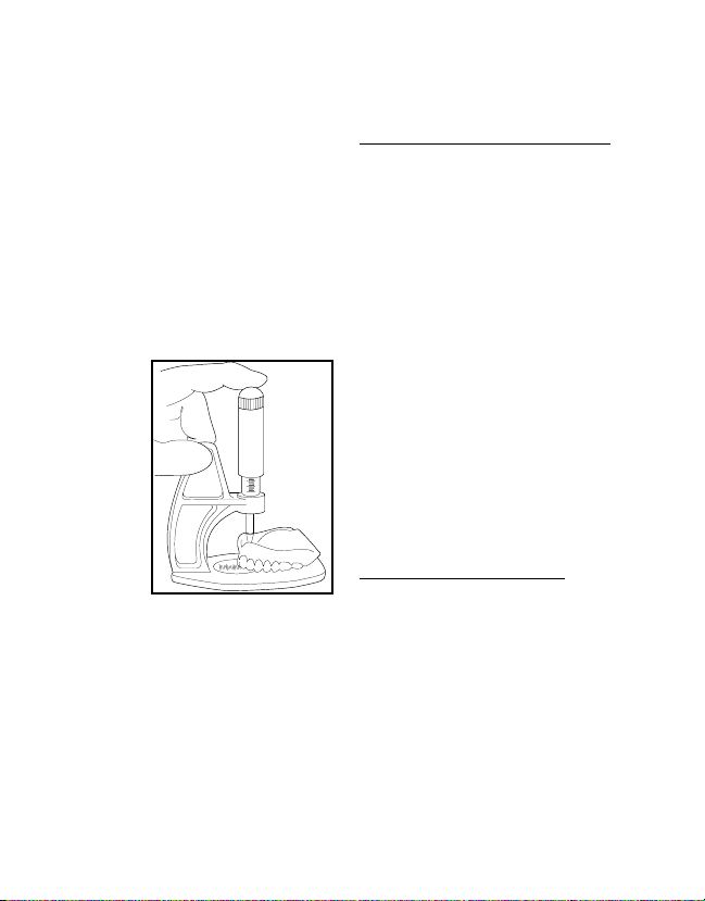
3. Pushing down on the black stylus
handle will allow the stylus point to
locate the incisive papilla depres-
sion in the acrylic base.
The vertical scale below the stylus
handle is read first (X mm) and then a
horizontal reading is taken (Y mm) on
the base where the incisal edge of the
teeth rest. A reading of 10X/8Y mm
indicates that the incisal edge of the
central teeth are 10mm vertical and
8mm horizontal to the incisive papilla.
If vertical space is not satisfactory,
see “Restoring Proper VDO In A New
Denture.”
In the case of the lower den-
ture, however, the ridge is subject to
continued resorption. A reline-type
impression should be taken inside the
fitting surface of the denture and this
will compensate for any gap.
(Alternatively, replace the gap
with some Triad®VLC Reline®
Material and take a new Alma
reading.) The Alma Gauge can now
be used confidently in the knowledge
that the recordings taken do relate to
the current shape of the lower ridge.
If a 2mm overbite relation-
ship is required, this has to be in-
corporated
in the lower
rim prescrip-
tion. If the
desired
lower incisal
edge posi-
tion is e.g.
10X/4Y, the
bite rim is
requested at
2mm less on the vertical e.g. 8X/4Y.
The try-in will then be 10X/4Y.
II. Use of Alma Gauge Shields
The Alma Gauge shields have
been designed in order to improve the
information that is passed between the
dentist and the technician, and also to
reduce the risk of cross infection.
A shield is placed on the base of
the Alma Gauge before a denture is
put into position. Two readings are
then taken from the scales, as noted
earlier.
A marker pen is then used to draw
around the denture onto the shield to
record the position of all the teeth
around the arch. To adjust the shape of
the bite rim, or the position of the
teeth, simply revise the drawing on the
shield.
The shield can then be removed
from the gauge and sent to the labo-
ratory along with the impressions and
other information.
The laboratory technician places
the Alma shield onto his/her gauge
and can produce the bite rim, try-in
and finished prosthesis to the required
dimensions and arrangement, refer-
ring as needed to the graphic outline
on the shield.
III. Restoring Proper VDO
In A New Denture
If the vertical height or freeway
space are not considered to be satis-
factory in the existing dentures, then
adjustments should be made to the
Alma Gauge readings. In those cases
where the teeth have worn down or
the overall vertical dimension is
reduced it will be necessary to
increase the Alma Gauge measure-
ments. This is achieved by adding
beading wax to the existing teeth until
an acceptable vertical height and
labial position have been reached.
Alma Gauge readings are then taken
and the dimensions sent to the labo-
ratory along with final impressions,
and a request to produce bite rims of
that size.
IV. LABORATORY PROCEDURES
Full Denture Technique
In the laboratory, the Alma Gauge
is used by the technician when con-
structing the bite registration rims.
When final trimming is performed on
the wax bite rim, they are reduced to
the dimensions prescribed by the den-
tist (i.e.: X/Y mm Alma measurements)
and checked by means of the Alma
Gauge. The width of the rims should
be similar to denture teeth to minimize
interference with phonetic evalua-
tions.
In the dental office this technique
saves time at chairside, and assures
proper bite rim dimensions.
Oftentimes, the bite rim(s) require little
modification at this stage, and the
dentist can focus on finalizing the
plane of occlusion and centric regis-
trations.
After
wax bite
rim try-in,
the rims are
returned to
the labora-
tory along
with all the
other details
recorded,
e.g. smile line, center line, etc. The
models are then articulated and a try-
in is constructed by the technician.
Once again the Alma Gauge confirms
that the incisal edges of the teeth
relate to the incisive papilla as
requested.
Back in the dental office, the
teeth are tried in the patient’s
mouth and centric registration, verti-
cal dimension, cosmetics, etc. are
examined. If the try-in is not correct,
specific details can be given for any
change in tooth position, e.g.
“change 10X/8Y to 8X/8Y”, rather
than the usual requests to “bring the
teeth in a little, they are too promi-
nent”. When the try-in is acceptable
to both dentist and patient, the teeth
are returned to the laboratory with the
final X/Y dimensions for processing,
Indicator stylus
handle
Vertical (X)
measurement
Base with
shield
Horizontal (Y)
measurement
4188_A.qxd 12/9/03 8:38 AM Page 2


