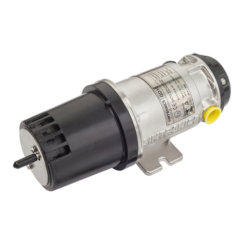
Simtronics GD10-P00 User manual

Operating Manual
Doc: 850-811250-R05
Infrared Point Gas Detector
GD10-P00

GD10P Page 2 of 32 850-811250-R05
Note
This manual must be carefully read by those who have or will have the
responsibility for the operation or maintenance of this product. The product may not
perform as designed if it is not used and maintained in accordance with the
manufacturer’s instructions.
The warranties made by Simtronics with respect to the product are voided if the
product is not used and maintained as described in this manual.
Please read the general warnings in chapter 7.
© Simtronics AS, all rights reserved.

GD10P Page 3 of 32 850-811250-R05
Table of contents
1.PRODUCT DESCRIPTION...................................................................................4
2.TECHNICAL SPECIFICATIONS...........................................................................5
3.INSTALLATION..................................................................................................7
3.1.Positioning ................................................................................................. 7
3.2.Fixing.......................................................................................................... 7
3.3.Weather protection ................................................................................... 8
3.4.Duct or pipe mounting............................................................................... 9
3.5.External cable.......................................................................................... 11
3.6.Electrical connection .............................................................................. 12
4.COMMISSIONING.............................................................................................13
4.1.Visual inspection ..................................................................................... 13
4.2.Power up.................................................................................................. 13
4.3.Checking system functions..................................................................... 13
5.OPERATION.....................................................................................................14
5.1.Analogue Output Protocol....................................................................... 14
5.2.HART® Interface ..................................................................................... 14
6.MAINTENANCE ...............................................................................................20
6.1.Cleaning of optical lens/mirror.............................................................. 20
6.2.Function test............................................................................................ 20
6.3.Calibration test........................................................................................ 21
6.4.Re-zero .................................................................................................... 21
6.5.Fault finding ............................................................................................. 23
7.WARNINGS......................................................................................................24
7.1.Ownership and confidentiality................................................................ 24
7.2.Liability..................................................................................................... 24
8.WARRANTY .....................................................................................................25
9.CERTIFICATIONS AND STANDARDS ...............................................................25
9.1.Standards................................................................................................. 25
9.2.Approvals................................................................................................. 25
9.3.Marking.................................................................................................... 26
9.4.Explanation of product coding................................................................ 27
10.ACCESSORIES AND SPARE PARTS .................................................................28
APPENDIX 1 #-codes for generic HART®GD10 ......................................................30
CONTACT DETAILS..................................................................................................32

GD10P Page 4 of 32 850-811250-R05
1. PRODUCT DESCRIPTION
The GD10P has been designed with features that provide an effective response to
the detection of gas hazards in a wide range of industrial environments from boiler
plant rooms to offshore petrochemical installations.
These infrared gas detectors differ from all other models, because they utilise
silicon based solid-state infrared sources. The complete opto-mechanical design
and construction is so stable that an ultra-fast speed of response can be achieved
whilst providing unparalleled service life and detector stability, thus saving on
maintenance and service costs.
We offer the longest combined detector and IR source warranty on the market.
For retrofit applications, a bridge interface is available allowing the detector to be
connected directly to catalytic systems, using the existing cabling and control
modules.
Supplied with worldwide performance (CSA / CENELEC) and hazardous area
approvals.
Suitable for use in SIL 2 and SIL 3 systems.
Compared with catalytic sensors, the GD10P has the following advantages:
Presence of oxygen is not required for correct measurement, which makes the
GD10P suitable even in an inert gas atmosphere.
No possibility of poisoning of the detector since no chemical reaction occurs,
i.e. silicon vapours and HS have no effect on the detector or the
measurement.
The gas flow rate has no influence on accuracy.
There are no saturation effects which could lead to false measurements. Thus,
the detector is capable of measuring gas concentrations up to 100% vol.
The detector has a continuous self-test function, and reports dirty optics and
fault conditions to the control system.
Total system costs can be dramatically reduced with the GD10P:
High reliability results in low test frequency and no calibration costs.

GD10P Page 5 of 32 850-811250-R05
2. TECHNICAL SPECIFICATIONS
Version: 0-100%LEL Methane, 5 sec. response time.
(Specification for other types on request)
GENERAL
Detection method IR-absorption, dual wavelength, dual path
IR-Source Solid state IR source, 50Hz flash
Gases detected Detector versions for several hydrocarbons as well
as CO2.
Self-test Continuous
Calibration Factory set, no field recalibration
PERFORMANCE
Lifetime stability *) ±5% of full scale (FS) reading
Accuracy *) ±3% FS between 0-50 % reading
±5% FS between 50-100 % reading
Response time T20 = 1 sec. (Optional 0.3 sec)
T50 = 2.5 sec. (Optional 0.7 sec)
T90 = 6 sec. (Optional 1.6 sec)
Start-up time *) Less than 60 sec., measuring 30 min. full
specification
*) Refers to -20°C to + 45°C
DETECTOR WARNINGS
Early Dirty Optics 55% signal attenuation
Dirty Optics 70% signal attenuation
Detector failure Main function fault or blocked optics.
OUTPUT SIGNAL
Standard Current source 4 – 20 mA, max. load impedance
500 Ohm
Option Current sink 4 – 20 mA
Maintenance HART® interface

GD10P Page 6 of 32 850-811250-R05
ELECTRICAL
Power supply 24 V DC, range18-32 V DC
Power consumption Approx. 3.5 W
Connection 3 wires (0.5mm2 - 1.5mm2)
Cable entry M20 Exe cable gland
TEMPERATURE RANGE
Storage -40°C to + 70°C (-40°F to +158°F)
Operating -40°C to + 65°C (-40°F to +149°F)
Humidity (operation) 100% RH
HOUSING
Main compartment Exd IIC T6 Gb
Terminal comp. Exe
Protection category IP66/IP67 DIN 40050
Housing material Stainless steel SIS2343 (ASTM 316)
Weight Approx. 2.9 kg (6.4 Lbs)
Dimensions 264L x 104W x 106H (mm)
10.4 x 4.1 x 4.2 (inches)
WARRANTY
5 years full warranty on complete instrument
15 years warranty on the IR-sources

GD10P Page 7 of 32 850-811250-R05
3. INSTALLATION
!
The area in which the detector may be installed must be in accordance
with the certification of the detector and in accordance with the standards
of the appropriate authority in the country concerned.
3.1. Positioning
The detector should be mounted where gas leakage is most likely to occur. To
detect methane, which is lighter than air, inside an enclosed area the detector
should be mounted high in the area to be protected or immediately above potential
leakage sites.
To detect gases heavier than air, e.g. propane, the detector should be mounted
below the potential leakage site.
The detector should be mounted in a place where maintenance, i.e. cleaning of the
optics, is easily performed.
The detector may be mounted in areas where no oxygen is present.
The detector may be mounted in areas with strong airflow
The detector should NOT be mounted where it could be drenched by water.
3.2. Fixing
The detector is mounted by means of a projecting mounting leg using two M8
screws and washers, or by means of the Duct Mounting Flange Kit (4 x M8 screws).
The detector should be mounted so that the longitudinal axis of the detector is
horizontal. This will prevent accumulation of water and dust on the optics. The
Weather Protection must always be oriented correctly for optimal performance.
Figure 3.1 GD10P mounted by means of mounting feet
Weather Protection
M8 screw

GD10P Page 8 of 32 850-811250-R05
3.3. Weather protection
See “Flow Direction Indicator” in Fig. 3.2 below. Orientation of the Weather
Protection is performed as follows:
Use a screwdriver to loosen the two screws on the Weather Protection
Rotate the Weather Protection to correct position
Tighten the screw with a torque of max. 0.5 Nm
Figure 3.2 Orientation of GD10P weather housing in relation to flow direction
!
When the GD10P is mounted outdoors, the flow direction indicator must
point upwards.
Flow direction
indicator

GD10P Page 9 of 32 850-811250-R05
3.4. Duct or pipe mounting
If installed in a ventilation duct or pipe, the mounting arrangement and accessories
shown in Figure 3.3 and 3.4 should be used.
The Duct Mounting Bracket shown in Fig. 3.3 allows the GD10P to be positioned in
the core of the airflow in wide ducts or pipes.
In order to achieve minimum response time, the Weather Protection must be
oriented with the flow direction indicator facing into the air flow. See Figure 3.2 and
3.4
The sensor must be mounted in straight parts of the duct with undisturbed airflow.
Avoid areas with possible turbulent flow e.g. immediately after sharp bends or
junctions.
The kit includes a modified weather protection as well as piping for functional
testing.
Alternative A
Remove cap when using
alternative A
Figure 3.3 Exploded view, Duct Mount Flange Kit
!
Avoid direct light on lens and mirror if the GD10P is mounted without the
Weather Protection.

GD10P Page 10 of 32 850-811250-R05
O
115,8
45°
45°
O
8,5 4x
5M 6M4x
O
150
O
170
Flange
599-811939
> 126 mm
Duct wall
Flow direction
indicator
Figure 3.4 Ventilation duct or pipe mounting using Duct Mounting Flange Kit
Refer to: Figure 3.3 for details.

GD10P Page 11 of 32 850-811250-R05
3.5. External cable
The cable type must be chosen in accordance with applicable regulations.
The table below indicates maximum cable lengths (2-wire) restrictions due to
voltage drop over the power supply cable.
Single wire cross area 0,5 mm20,9-1 mm21,5 mm2
Supply voltage 24VDC 250m 500m 750m

GD10P Page 12 of 32 850-811250-R05
3.6. Electrical connection
The terminal compartment is accessible by removing the circular terminal cover.
(Loosen the four M5 bolts).
The terminal compartment, including the terminals for electrical connection, is
shown below.
The installation wiring enters the terminal compartment via a single M20 Exe cable
gland, which can be mounted on either side of the compartment. The unused entry
is blanked with an Exe cover.
Figure 3.5 Terminal compartment
!
The detector housing must be connected to local ground via the external
earth point. The wire should be minimum 4 mm2 (8 AWG) and as short as
possible.
The shield of the cable should be connected to instrument earth in the central
control module, and is normally not terminated at the detector. Exception: If extra
RFI protection is required, and the installations grounding principles/regulations
allows it, the shield is terminated to local ground via the internal earth point at the
detector.
On UL variants, the terminal compartment is not used. Cables are instead led out of
a bushing, and each cable termination is numbered as above.
Internal earth
p
oint Terminal 5 Factory use only
Terminal 4 Factory use only
Terminal 3 4-20 mA output
Terminal 2 24 V return (0 V)
Terminal 1 +24 VDC
External earth
p
oint

GD10P Page 13 of 32 850-811250-R05
4. COMMISSIONING
4.1. Visual inspection
The following should be checked before initial powering up:
The axis of the detector shall be horizontal.
Correct cable gland installation
Electrical connection
Electrical grounding
Termination of cable shield
Orientation of the weather protection
All bolts and screws are tight
Please refer to the Installation chapter for details.
4.2. Power up
Ensure that system wiring and control system
are in working order before powering the
detector. The startup period takes about 60
seconds, a functional self-test is performed
during this time. When the self-test is completed
the detector turns over to measuring mode. The
4-20mA output will stay at 0mA during the 60
seconds startup period and 4mA (if no gas is
present) in measuring mode. The graph on the left shows the reading of the 4-20mA
analog output during startup period.
4.3. Checking system functions
The GD10P is factory calibrated, and does not require any adjustments before
operation. A check prior to putting into service should however consist of:
1) Clean the optical surfaces
The detector may have been collecting dirt after being initially installed. It is thus
crucial to clean the optical parts before testing the detector.
Please refer to: “6.1 Cleaning of optical lens/mirror”.
2) Do a gas test
To make sure the detector works you should as a minimum do a function check as
described in “6.2 Function test”. Optionally you may do a full calibration test as
described in “6.3 Calibration test”.

GD10P Page 14 of 32 850-811250-R05
5. OPERATION
5.1. Analogue Output Protocol
Gas reading and fault signalling is given through the 4-20mA current loop interface.
The table below shows the analogue output level for the various conditions.
Condition Analogue output Comment
Normal gas reading 4 mA - 20 mA 4 mA = 0% of range
20 mA = 100% of range (or higher)
Early Dirty Optics
Warning
(55% signal reduction)
2 mA *) Detector will still output gas
concentration if it is greater than
7 % of range (FS)
Dirty Optics Warning
(70% signal reduction)
1 mA *) No detection
Detector Fault < 0,5 mA *) No detection
*) Shows default factory setting. Can be configured via HART® terminal
5.2. HART® Interface
5.2.1. Introduction
Simtronics GD10P detector supports HART® version 7.
For proper operation between GD10P and the HART® communicator, a dedicated
Device Descriptor (DD) should be loaded onto the communicator. If such DD is not
present, the communicator will offer a proprietary generic interface, and the list of
available functions may be limited and variable.
The proper DD for GD10P can be downloaded from HART® Foundation website
www.hartcomm.org (search for Simtronics under “Product Catalog” “Wired
Products”, or requested directly from Simtronics. The loading of the DD onto a
specific communicator must be done according to the relevant user guide for that
communicator.
!
DD has no relevance for earlier versions of GD10 (the generic HART®
devices). Customers having such detector still need to use #-codes
described in Appendix 1 at page 30 of this manual.

GD10P Page 15 of 32 850-811250-R05
5.2.2. Connection
For access to the detectors HART® features, connect an industry standard HART®
communicator as shown in the following figures depending on the type of analogue
interface (source or sink).
Note that for the HART® communication to work properly, a minimum loop
resistance is required in the current loop. The actual value of the serial resistance
in the diagrams below may vary depending on the rest of the resistance in the loop.

GD10P Page 16 of 32 850-811250-R05
5.2.3. HART® Menu Map

GD10P Page 17 of 32 850-811250-R05
The menu map on the previous page, shows the complete list of available
commands in the HART® interface of GD10. Most of the commands are only
requests to read information from the detector. The commands shaded as grey with
bold text gives the operator possibility to make changes to individual parameters,
and these commands are described further in the following sections.
5.2.4. Detailed description of selected commands
When one of the following commands are activated, the operator is navigated to one
or several data input screens where detailed data can be entered, or predefined
options selected. Detailed navigation between the commands is not explained, as
this is part of the user interface of the actual HART® communicator.
5.2.4.1. TAG (Basic setup)
The operator can write an alphanumeric text, max 8 characters. Default is “GD10”.
5.2.4.2. Long tag (Basic setup)
The operator can write an alphanumeric text, max 32 characters. Default is empty.
5.2.4.3. Descriptor (Basic setup)
The operator can write an alphanumeric text, max 16 characters. Default is
“SIMTRONICS A/S”.
5.2.4.4. Date (Basic setup)
The operator can write a date on the format MM/DD/YY. Default is **/**/**.
5.2.4.5. Message (Basic setup)
The operator can write an alphanumeric text, max 32 characters. Default is
“SIMTRONICS A/S”.
5.2.4.6. Final asmbly num (Basic setup)
The operator can write an alphanumeric text, max 8 characters. Default is “0”.
5.2.4.7. SET RESPONSE TIME (Detailed setup)
The operator can choose between two response modes. Default is “5s”.
5.2.4.8. SET FAULT OPTION (Detailed setup)
The operator can choose between three options according to the following table.

GD10P Page 18 of 32 850-811250-R05
Option Detector fault Dirty Optics Early Dirty
Optics
(see note 1)
OP0
(factory default)
<0.5mA 1mA 2mA
OP1 1mA 2mA 3mA
OP2
(User
selectable)
1(0mA)
2 (1 mA)
3 (2 mA)
4 (3 mA)
1(0mA)
2 (1 mA)
3 (2 mA)
4 (3 mA)
1(Don’tcare)
2 (1 mA +
pulsing)
3 (2 mA)
4 (3 mA)
Note 1: If in “Early Dirty Optics” state, the detector will switch to standard
output level when gas reading is >7% of detection range.
After a reconfiguration, it is recommended to restart the detector and verify the
new settings by simulating different alarm/warning states. A current meter may be
used to read the level at the analogue output.
5.2.4.9. PV unit (Detailed setup)
The operator can choose between several measurement units. Default is “%LEL”.
5.2.4.10. GD10 Zero Trim (Diag/Service)
When this function is activated, the operator gets on-line instructions on how to
support the function. The analogue output will drop down to 1mA to indicate the on-
going zeroing process, which takes about 3-4 minutes to complete. The analogue
output returns to the actual zero (4mA) when zeroing process is completed. Zeroing
will not take place if the ambient temperature is outside a specific temperature
range (around 20 – 30 deg C). If the Zero level is not improved after the zeroing, the
reason is that the zero drift is over the allowed limit for field trimming.
!
This function should be activated by special trained operators. If zero
trimming is not done in a controlled way, the performance of the detector
can be reduced. Also, prior to launching this function, read the detailed
descriptions in section 6.4.

GD10P Page 19 of 32 850-811250-R05
5.2.4.11. GD10 Loop Test (Diag/Service)
A fixed analogue output level can be used to test the analogue output loop. Such
fixed analogue output level can be obtained with this function. The operator can
choose one of the pre-set levels, or specify a user defined level.

GD10P Page 20 of 32 850-811250-R05
6. MAINTENANCE
!
The GD10P has no user adjustable parts. It is not recommended to open
the GD10P, as this will change the internal atmosphere, and the initial
calibration could be affected. Opening the GD10P voids all warranty
offered at the time of sale.
6.1. Cleaning of optical lens/mirror
Remove the weather protection by unscrewing the front cover plate (two screws),
use a soft, clean tissue to rub off the contamination. The window and mirror are
made of sapphire, which is highly resistant to scratching. Make sure that the whole
optical surface is clean.
!
For difficult contaminants the mirror and lens can be cleaned with an
equal-part mixture of isopropyl alcohol and water. Do not perform any
testing of the detector before this solution has dried and residues have
been wiped away.
6.2. Function test
In order to perform function test of the detector, a test gas can be applied through a
6 mm test nozzle on the front of the Weather Protection housing as the drawn
shown below and observe the effect on the detector 4-20mA analog output or
through the control system.
This is a simple test to verify the main function of the detector, please note the
actual reading may be substantially lower than the calibration gas concentration
due to leaks/ventilation of the weather protection. As long as the detector responds
to the gas, the function of the detector is verified.
1) Clean the optical surfaces
2) Verify that the zero point (at no gas) is within the tolerance
for the detector. Normal readings should be below 4.5mA
3) Apply gas as shown. If there is no air movement, a test gas
flow of minimum four liters per minute will give approximately
the same value as the test gas.
If there is an air movement of 0.5 m/sec., the test gas flow has
to be increased (up to 20 liters per minute) to get a reasonable
reading. Covering the ventilation grille will also help getting a
Other manuals for GD10-P00
2
Table of contents
Other Simtronics Other manuals
Popular Other manuals by other brands

West Coast Corvettes
West Coast Corvettes C7 Corvette Mild 2 Wild NPP Option instructions

Gantner
Gantner GT7.2500 manual
K&K Sound
K&K Sound PURE 12-STRING product manual
Telcoma Automations
Telcoma Automations SNAP 4 Operation and Programming Instructions

Martin
Martin QC 1 HD MT installation manual
Idesco
Idesco 7C 2.0 installation instructions
