Pro-gard Products LLC. P1000 Pro-Cell User manual

STRONG
|
RELIABLE
|
SECURE
INSTALLATION GUIDE
P1000 PRO-CELL
2015
DODGE CHARGER
pro-gard.com
800.480.6680
pro-gard.com
800.480.6680 2
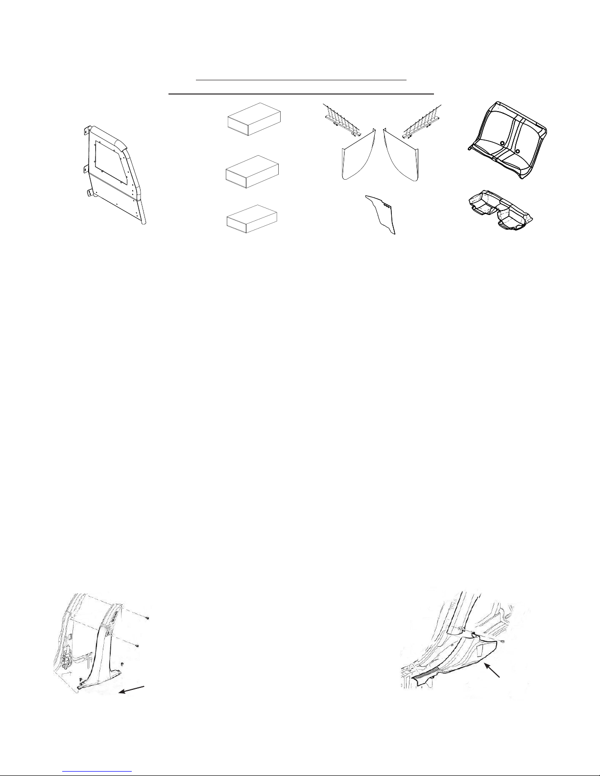
I. Refer to the diagram on the last page of these instructions to verify all parts were received.
II. The following tools will be required to complete the installation.
A. 1/4” or 3/8” drive ratchet with 3/8”, 7/16”, 7mm, 10mm, 18mm, socket
B. 3/16” Allen key
C. 1-1/2” Hole saw
D. Drill with 3/8” Socket
E. T15 Torx Driver
III. Read all instructions carefully before starting the assembly process.
Caution: Locate all Wiring, Fuel Lines, Brake Lines, and/or Cooling Lines before drilling holes or installing Fasteners.
IV. Removing the OEM Trim Panels
A. Remove B-pillar trim on the Driver and Passenger-side. These will be reinstalled after
bracket installation. Note: From the head liner down the trim is held in place by
snap fasteners but the top of the trim panel is held in place with a screw. Pull head liner
down and away from the trim panel and use a T15 torx driver to remove the screw.
(See Fig. 1)
B. Remove the Rear Door Scuff Plates on the
Driver and Passenger-side. These will be
reinstalled after the ABS Floor Pan Installation.
(See Fig. 2)
THESE COMPONENTS ARE REQUIRED
TO INSTALL THE PRO-GARD PRO-CELL SYSTEM
S56C11 Seat
4P1000 Pro-Cell Partition 4S56C11 Seat Kit 3P5615 Divider
4K56C11 Partition Kit
4K56C11 Partition Kit
FP56C11 Floor Pan
WB56C11 WB & DP
Fig. 2
PASSENGER SIDE SHOWN
REAR DOOR
SCUFF PLATE
Fig. 1
PASSENGER SIDE SHOWN
B-PILLAR TRIM
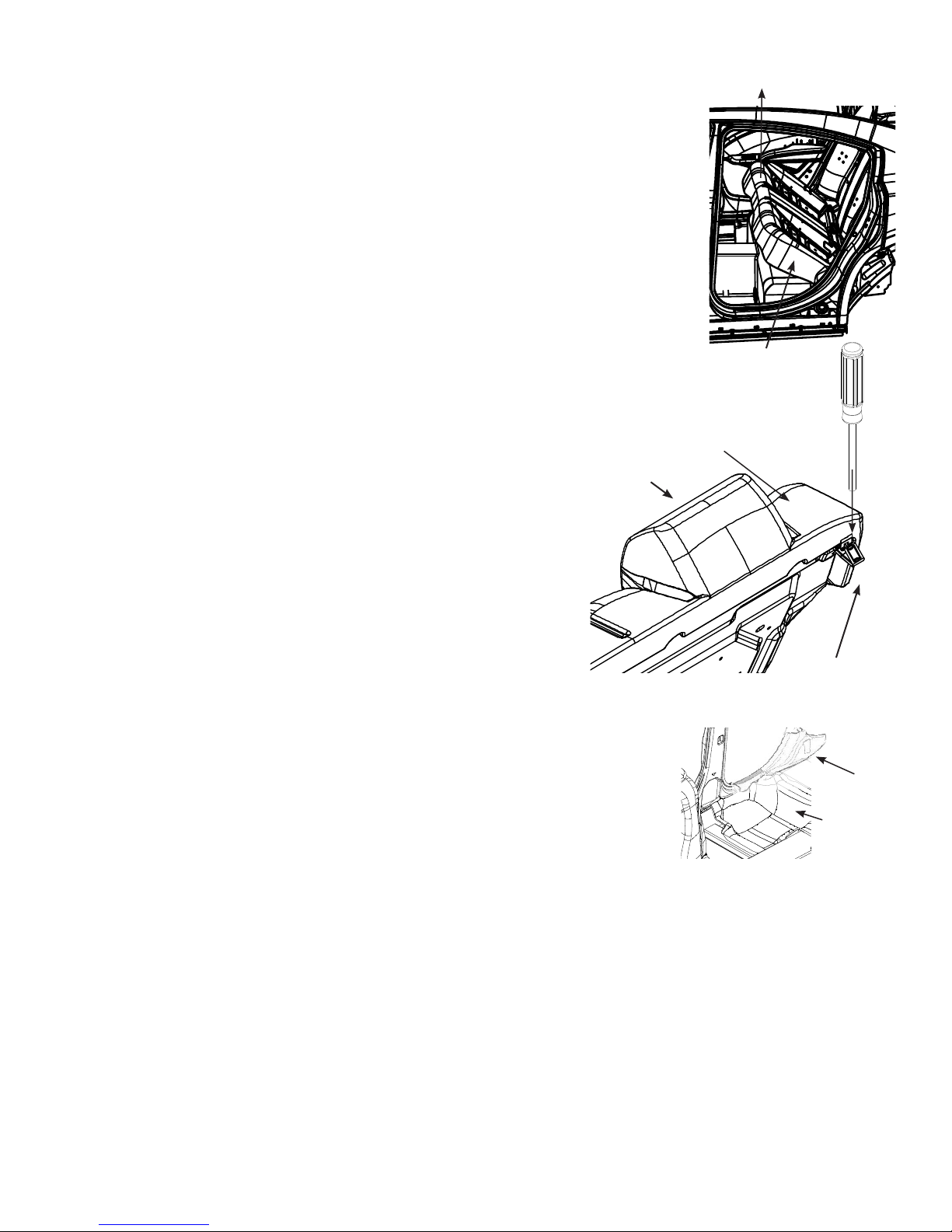
V. Removing the OEM Seat
A. Begin by lifting the lower seat cushion out from the rubber grommets
intheoor.Oncetheseatisfreeremovefromthevehicle(SeeFig.3).
B. Remove the seat belts by removing the OEM nuts from their mounting
studs. Do not remove the shoulder straps anchored at each side of the
vehicle.
C. Remove the OEM seat back cushion by removing two 18mm nuts from
the lower mounting brackets near the seat belt mounting studs. Using a
screwdriver and depressing from above, release the OEM spring locking
tabs located on the top outer corners of the seat. (See Fig. 4)
D. With the seat removed, the OEM child restraint loops are exposed.
Remove the child restraint loops or bend them downward toward the
oor.Note: This is necessary for the Pro-gard Seat to t properly in position.
VI. Installing the ABS Floor Pan
A. Place the ABS Floor Pan in the vehicle, making sure that
there are no objects underneath of it. Insure that the Floor
Pan is all the way back and down against the rear seat area.
Note: The oor pan does not cover the OEM seat grommets.
Note: Floor pan may require securing to vehicle near “B” pillar
with screws
B. Reinstall the OEM Rear Door Scuff Plates on the Driver
and Passenger-side. (See Fig. 5)
Note: The Door Scuff Trim Plates go on top of the ABS Floor Pan.
Note: Minor Trimming to the lower portion of the Door Scuff trim may be required.
Note: For a more secure t, a screw where the door scuff trim and the “B” pillar
trim overlap may be required.
VII. Installing the ABS Transport Seat
A. Mount the Seat Locating Tabs (3S5601) to the bottom of the ABS
Seat using the supplied bolts (3X03) and the lock nuts (3X03).
(See Fig. 6)
B. Attach the (3P214) Divider Mounting Brackets using the supplied bolts (3X36) and whiz nuts
(3X16Z), before installing the seat in to the vehicle. (See Fig. 6)
Note: The at side of the bracket should face the driver’s side, the divider will mount at against it.
C. Place the seat in the vehicle. Make sure the locating tabs slide into the OEM seat grommets in the
oorofvehicle.Theseatwilllapoverthebackedgeoftheoorpan.
D. The seat has a seat belt relief notches at each side. Position the seat belt straps in each relief, insuring
the seat belt has free travel through out it’s cycle.
Fig. 3
DRIVER SIDE SHOWN
REAR SEAT
LOWER CUSHION
pro-gard.com
800.480.6680
3
Fig. 4
OEM REAR SEAT
LOCKING TAB
PASSENGER SIDE SHOWN
REAR SCUFF PLATE
Fig. 5
ABS FLOOR PAN
UP

A. Prep. seat belt assemblies at this point by removing the plastic “Sheath” around
base of each set of belts, and by removing the brass washer holding the center belts together
at the mounting plate.
B.Inserttheseatbelts,mountinglugsrst,throughtherubberseatbelt
grommets. Pass the seat belt lug through the slot in the seat belt cover
plate and install the rubber grommet into the slot of the cover plate.
Slide the cover plate/grommet assembly up the belt towards the buckles.
(See Fig. 7)
C. Insert the seat belt lug through the hole in the seat and reattach to OEM mounting stud with
OEM nut. Radially orient and tighten with 18mm socket wrench. Slide cover plate and
grommet assembly down the belt and into the recess in the seat. Radially
orient and secure using the (3X72) Phillips truss head screws.
IX. B-Pillar Bracket Installation
A. Place the Passenger B-pillar bracket (3PRT5611-01P)
against the B-pillar face (See Fig. 8).
C.OrientatetheB-pillarbracketsothebottomtabts
into the “T” slot on the B-pillar and the formed
edges wrap around the B-pillar. Using the supplied
Self-Drilling screws (3X162) secure the B-pillar.
X. Drilling B-pillar Trim Panel
A. Remove the sound insulation located inside the
E. Secure the outside front corners of the seat by
using the supplied 5/8” long self-tapping screws
(3X177)andnishwashers(3X78)ateach
end of the seat near the C-pillar trim using
the pre-drilled holes provided in the seat.
Note: The gas tank is under the rear seat in this vehicle. Use pre-
drilled locations and supplied hardware only!
Caution: Locate all Wiring, Fuel Lines, Brake Lines, and/or
Cooling, Lines before drilling holes or installing Fasterners.
F. Use seven 1-1/2” long (3X77) self-tapping screws
and(3X78)nishwasherstosecurethemiddlefront
(2) and top rear (5) of the seat using pre-drilled
holes provided in the seat.
VIII. Installing the OEM Seatbelts and ABS Cover Plates.
pro-gard.com
800.480.66804
VEHICLE B-PILLAR
Fig. 6
PASSENGER SIDE SHOWN
3P214
3X36
3S5601
3X16Z
3X36
3X36
3X162
3PRT5611-01D
3X162
3X162
3X162
3X162
T-Slot
Fig. 8
PASSENGER SIDE SHOWN
Fig. 7

pro-gard.com
800.480.6680
5
Passenger-side trim panel, carfully align the Template
per their included instructions. Using a 1” Hole Saw
drill the clearance holes as marked on the template.
Replacment of sound insulation is optional.
B. Replace the trim panel, insureing that the standoff’s
protrude through the panel.
XI. Installing Partion Mounting Plate
A. Attach the Passenger-side Mounting Plate
(3PRT5611-02P) using the supplied 5/16-18 x 3/4”
Button head screws (3X149) to the standoff’s protruding
through the B-pillar trim (See Fig. 9). Hand tighten only.
XII. Installing Center Hump Mount Bracket
A. Insure that the OEM center consle is removed.
B. Install the Center Hump Mount Bracket (3PRT5611-03)
using the OEM console mount tabs, secure with the
included Screws (3X162). (See Fig. 10)
XIII. Installing the Partition
STANDOFFS
3PRT5611-01P
3X149
B-PILLAR TRIM
A. Insert the partition into the vehicle, lift and position the
partition so that it alines with the Partition Mounting Plate,
and Center Support Bracket. Secure the Partition using the
supplied 1/4-20 x 3/4” Carriage Bolts (3X36) and 1/4-20
Whiz nuts (3X16Z) Hand tighten only.
B. Level the partition by placing a torpedo level on the hem
at the bottom front side of the partition. Raise the center
of the partition slightly above level as the brackets will
settleintotheoorcoveringintime.Tightenthetwobolts
through the top of the Center Support racket. Check for level.
Tighten all fasterners.
XIV. Installing the Lower Extension Panel
A. Place the Panel against the back side parttion alinging the mounting
holes. Secure with carriage bolts 3X36 and nuts 3X16Z four places.
XV. Installing the Center Divider.
A. Assemble vent plate over 3 large diameter air holes. Use (blk ABS)
spacers between plate and center divider. Secure using the long,
Philipsheadscrews,blackwhiznuts,andblackcaps.(Seeg.11)
Fig. 10
3PRT5611-03
3X162 (4)
FIG. 11
Fig. 9
PASSENGER SIDE SHOWN

B. Insert the center divider from the passenger side of the vehicle. Be sure to start with the tail of the
divider, aimed toward the rear window and speaker deck area. Once you have inserted the divider,
press the divider against the seat mount brackets, and then to the partition tabs Mark all mounting
hole locations on the divider with a felt tip marker then remove the divider for drilling or drill in
place if desired.
C. Once you’ve installed the divider, mount the divider deck bracket in place. Slide the T-bracket under
the divider tail. Position the T-bracket where desired and use the (3X110) self-tapping screws to
fasten the bracket into the speaker deck (See Fig. 12).
D. Use the existing holes and slots on the bracket as a template,
and drill holes to secure each area using the 3X61 carriage
bolts and the 3X16Z whiz nuts.
XVI. Air Bag wing Installation
A. The Filler Wings and their mounting hardware are packed
in separate box marked Wing Kit. Install the Filler Wings
according to thier included Install Instrutions. (See Fig. 1)
XVII. Door Panel Instalation.
A. The Door Panels and their mounting hardware are packed
in separate box marked DP5611 . Install the Door Panels
according to thier included Install Instrutions. (See Fig. 14)
XVIII. Window Barrier Instalation
A. The Window Barriers and their mounting hardware are packed
in separate box marked WB56C11. Install the Window Barriers
according to thier included Install Instrutions. (See Fig. 14)
XVI. Finalize Instalation
A.Audittheoverallinstallationfortandfunctionofallcomponents.
Oncesatised,insureallfastenersaretight.
B. Instalation is now complete
pro-gard.com
800.480.6680
6
FIG. 12
FIG. 14
FIG. 13

7
pro-gard.com
800.480.6680
PARTS LIST
DESCRIPTION
PART NUMBER
QTY
ITEM
PARTITION ASSEMBLYVARIES11
MOUNT BRACKET - DRV, B-PILLAR3PRT5611-01D
1
2
MOUNT BRACKET - PASS, B-PILLAR3PRT5611-01P13
PARTION MOUNTING PLATE - DRV3PRT56611-02D14
PARTION MOUNTING PLATE - PASS3PRT5611-02P
15
SLF DRILL SCREW, #14 x 3/4"
3X167106
BHCS, 5/16-18 x 3/4"3X1496
7
WHIZ NUT - LARGE , 1/4-20
3X16Z158
CARRIAGE BOLT, 1/4-20 x 3/4"
3X3639
CENTER DIVIDER, 3/8" POLYCARBONATE3P5611-D
1
10
LOWER EXTENSION PANEL - FULL WIDTH3SP5611-01111
ABS FLOOR PANFP56C06
1
12
ABS TRANSPORT SEATTT56C06113
BRACKET - DIVIDER, MOUNTING3P214314
MOUNTING TAB - SEAT3P56012
15
VENT PLATE - DIVIDER3P8010116
SPACER - BLK PLASTIC, 3/8"4G5070PI
417
WHIZ NUT, 1/4-20 BLK GR8
3X16418
PHTS, BLK 1/4-20 X 1 1/2"
3X07419
DRAIN PLUG3S601
1
20
1/4-20 x 3/4" CARRAIGE BOLT
3X61121
ABS DOOR PANEL, PASSENGERDP56C11P
1
22
ABS DOOR PANEL DRIVERDP56C11D123
WINDOW BARRIER, PASSENGERWB56C11-01P124
WINDOW BARRIER, DRIVERWB56C11-01D
1
25
777
7
7
7
888
6
66
6
4
44
5
1
444
66666
2
4
11
12
23
25
22
24
8
8
8
8
99
15
15
9
1414
14
88
13
21
2121
1919
19
19
17
17
17
17
21
8
8
8
8
9
10
1818
18
18
16
PARTS LIST
DESCRIPTION
PART NUMBER
QTY
ITEM
PARTITION ASSEMBLYVARIES11
MOUNT BRACKET - PASS, B-PILLAR3PRT5611-01P
1
2
MOUNT PLATE - PASS, SHEETMETAL3PRT5611-02P13
SUPPORT BRACKET, CENTER3PRT56611-0314
SLF DRILL SCREW #14 x 1"3X110
15
SLF DRILL SCREW, #14 x 3/4"
3X167106
BHCS, 5/16-18 x 3/4"3X1496
7
WHIZ NUT - LARGE , 1/4-20
3X16Z158
CARRIAGE BOLT, 1/4-20 x 3/4"
3X3639
CENTER DIVIDER, 3/8" POLYCARBONATE3P5611-D
1
10
LOWER EXTENSION PANEL - PRO-CELL3SP5611-03111
ABS FLOOR PANFP56C06
1
12
ABS TRANSPORT SEATTT56C06113
BRACKET - DIVIDER, MOUNTING3P214314
MOUNTING TAB - SEAT3P56012
15
VENT PLATE - DIVIDER3P8010116
SPACER - BLK PLASTIC, 3/8"4G5070PI
417
WHIZ NUT, 1/4-20 BLK GR8
3X16418
PHTS, BLK 1/4-20 X 1 1/2"
3X07419
DRAIN PLUG3S601
1
20
1/4-20 x 3/4" CARRAIGE BOLT
3X61121
ABS DOOR PANEL, PASSENGERDP56C11P
1
22
ABS DOOR PANEL DRIVERDP56C11D123
WINDOW BARRIER, PASSENGERWB56C11-01P124
WINDOW BARRIER, DRIVERWB56C11-01D
1
25
WING KIT
W5611-A/W5611-R
226
1
11
4
9
5
3
2
6
9
26
8
8
7
1
3P5615
Table of contents


