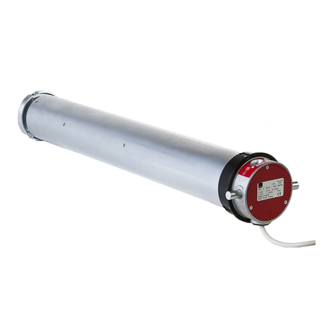
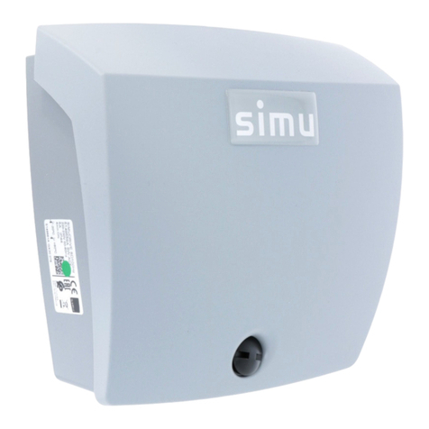
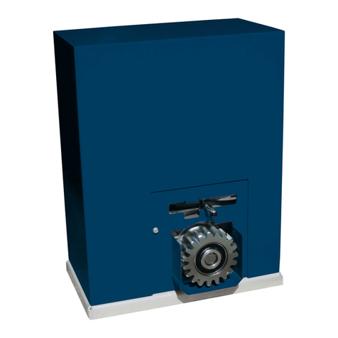
Simu MEMENTO User manual

1——
THE BRAND OF PROFESSIONALS
For over 65 years, SIMU has built on its industrial expertise and founding values in order to offer quality products
and services to its worldwide customers.
INVENTOR OF THE TUBULAR MOTOR FOR ROLLER SHUTTERS IN 1959!
In 1959, SIMU invented the tubular motor for roller shutters, a technology which has become the market standard.
Since then, we have continued to expand our knowledge and our expertise of the market and of our customers’
activities.
With over 65 years of experience, SIMU has become a reference brand in France and on the international stage!
MANUFACTURERS OF MOTORS AND AUTOMATIC CONTROLS
FOR ROLLER SHUTTERS, SUN BLINDS,
INDUSTRIAL AND COMMERCIAL CLOSURES SINCE 1952
STRONG
TECHNICAL
KNOWLEDGE
35 TECNICIANS &
ENGINEERS
HIGH
service
LEVEL
97%
DELIVERY RATE
OF OUR
MOTORS
ARE TESTED
100%
A HUMAN
ADEVENTURE WITH
260 EMPLOYEES
C
U
S
T
O
M
E
R
P
R
O
X
I
M
I
T
Y
MAXIMUM LOAD RAISED
BY OUR INDUSTRIAL
MOTORS
800
OF OUR CUSTOMERS
WOULD RECOMMEND US
100%

—— 2 3 ——
simu services
ONLINE support
services
DAILY,
OUR TECHNICIANS ANSWER
TO YOUR TECHNICAL QUESTIONS
AND ASSIST YOU WHEN
YOU NEED HELP
FOR INSTALLATION,
ADJUSTMENT OR
TROUBLESHOOTING
OF SIMU PRODUCTS.
CONTACT
CUSTOMER SERVICE
Tel. +33 3 84 64 75 00
Our technicians will answer you from Monday to Friday
from 8am to 12pm - 1.30pm to 5.15pm (4pm on Friday)
Excluding public holidays and closure periods
FOLLOW US
www.simu.com
FAQ, for immediate answers to the most frequently
asked questions about our products.
The online catalogue with all available references
available and their technical documentation;
Tutorials installation
and step-by-step adjustment
Your online ordering platform,
reserved for SIMU professional customers
(Metropolitan France). To order, consult your
prices or track your order
@
SIMU GUARANTEES
SIMU GUARANTEES ITS PRODUCTS FOR ITS PROFESSIONAL CUSTOMERS AGAINST ALL MANUFACTURING,
DESIGN OR MATERIAL FAULTS.
yOU ARE:
o A professional, a direct customer of SIMU : the full waranty applies.
o An individual or indirect customer of SIMU : please contact your installer or reseller to know the details of the
waranty applicable to you.
o
Tubular motors
o Central motors
o GM motors
o BOX and BOX SI motors
o Electronic products
o Battery and solar panel from the
AUTOSUN system sold alone
o Accessories (excluding cells and
batteries)
o LiveIn2 box.
o Plug Hz and BHz ON/OFF
o Sun sensor BHz
o Manual components
o Safety brake
o LiveIn2 Wi key
o Full solar solution AUTOSUN 2
(T3.5EHzDC motor + battery +
panel)
WARRANTY
7
M
o
t
o
r
-
B
a
t
t
e
r
y
-
S
o
l
a
r
p
a
n
e
l
PRODUCT
WARRANTY
5
PRODUCT
WARRANTY
2
PRODUCT
WARRANTY
1
AFTER-SALES SERVICE
Is a product under warranty has a failure? Contact us!
The SIMU After Sales Service will repair or replace it within 2 weeks
(as soon as we receive the defective product).
Our General Terms and Conditions of Warranty and the After Sales Service return form
are available on www.simu.com in the "Support / Warranty" section
simu formation
We accompany our professional customers through to training. Our
training department offers a programme of technical courses to help you
get to know SIMU products and understand their installation, adjustment
and programming rules.
To nd out more about our training offer, please contact your usual SIMU
sales consultant.

CONTENTS
—— 4 5 ——
INTRODUCTION
IDENTIFIFYING A MOTOR STICKER p. 6
SECURITY p. 8
- The control mode p. 9
- Installation recommendations p. 9
WIRING PRECAUTIONS p. 10
o
CENTRIS
WIRED CENTRAL MOTOR p. 11
- Installation p. 12
- Wiring with key switch p. 13
- End-limits setting p. 14
- Troubleshooting p. 15
o
CENTRIS VEOHZ
RADIO CENTRAL MOTOR p. 17
- Installation p. 18
- Wiring p. 19
- Compatible transmitters p. 19
- End-limits setting p. 20
- Command mode p. 21
- Validation of the rst command point p. 21
- Control of the visual command p. 22
- Use p. 22
- Optionnal settings p. 23
- Troubleshooting p. 25
o
T8, T8M, T8S, T8S DMI
SINGLE-PHASE MOTOR p. 27
- Installation tubular motors T8 and T8M p. 28
- Installation tubular motors T8S and T8S DMI p. 29
- Wiring with key switch p. 30
- End-limits setting p. 32
- Troubleshooting p. 33
o
T9, T9M
THREE-PHASE MOTOR p. 35
- Installation p. 36
- Examples of installation p. 37
- Wiring three-phase motor with SD350 - with manual override - 400V p. 38
- Wiring three-phase motor with SD350 - without manual override - 400V p. 40
- Wiring three-phase motor with SD350 - with manual override - 230V p. 42
- Wiring three-phase motor with SD350 - without manual override - 230V p. 44
- Wiring three-phase motor with SD510 - with manual override - 400V p. 46
- Wiring three-phase motor with SD510 - without manual override - 400V p. 48
- Wiring three-phase motor with SD510 - with manual override - 230V p. 50
- Wiring three-phase motor with SD510 - without manual override - 230V p. 52
- End-limit settings p. 54
- Troubleshooting p. 55
o
SIMUBOX
EXTERNAL MOTOR p. 57
- Installation p. 58
- Single-phase SIMUBOX motor wiring with key switch p. 60
- Three-phase SIMUBOX motor wiring with key switch p. 62
- Three-phase SIMUBOX smotor (no EI) wiring with SD510- 400 V p. 64
- End-limits setting p. 66
- Troubleshooting p. 69
o
SIMUBOX SI
EXTERNAL MOTOR p. 71
- Installation p. 72
- SIMUBOX SI motor wiring with key switch p. 74
- End-limits setting p. 76
- Troubleshooting p. 77
o
SD100HZ
RADIO CONTROL BOARD p. 79
- Installation p. 80
- Installation and wiring p. 81
- Box setting p. 86
- Troubleshooting p. 90
o
SD350
CONTROL BOARD p. 93
- Installation p. 95
- Wiring of three-phase motor with SD350 - with manual override - 400 V p. 96
- Troubleshooting p. 98
o
SD510
CONTROL BOARD p. 99
- Presentation p. 101
- Power wiring p. 103
- Three-phase tubular motor wiring with SD510 - with manual override - 400 V p 104
- SIMUBOX three-phase motor (no EI) with SD510 - 400 V p 106
- End-limits setting p. 108
- Key switch connection p. 108
- Safety device connection (for a shutter which cannot lift a person) p. 109
- Safety device connection (for a shutter which can lift a person) p. 112
- First power on p. 115
- Expert level parameters p. 123
- Consulting and programming maintenance p. 127
- Troubleshooting p. 132

7——
MOTOR STICKER
—— 6
Each SIMU motor has an identication sticker with a unique registration number, stuck on the tube, useful to have
its technical information and ensure its traceability.
IDENTIFYING A MOTOR STICKER
In case of repairing or of after-sales service, you may encounter motors with different stickers: there are older sticker models.
However, the information given will be the same as those presented above.
STICKER FOR UNIQUE REGISTRATION WITH DATAMATRIX & BARCODE
STICKER FOR UNIQUE REGISTRATION WITH DATAMATRIX
STICKER FOR UNIQUE REGISTRATION WITH DATAMATRIX
Technical reference + index
Production code (PPP)
Production year (YY)
Production day (DDD)
Production hour (HH)
Production minute (MM)
Production second (SS)
Technical reference + index
Torque (Nm)
Origin
Standards &
Homologations
Product
reference Current (A)
Cycles number per hour
Waste
treatment
Power supply (V)
Speed of the motor (rpm)
Frequency (Hz)
Operating
temperature
Description (reference only for internal use)
Protection
index against
solid and
liquid parts
Power of the motor (W)
NEW
2 detachable parts to stick on the outside
of the tube
Continuous operating time
The datamatrix and the barcode provide a code enabling the traceability of the motor:
Unique traceability with datamatrix (16x16mm)
Technical reference
+ index
Origin
Origin
Product name
Product name
Traceability: datamatrix
Traceability: datamatrix
Unique production code
Waste treatment
Waste treatment (battery)
Technical reference + index
Unique production code
Standards & Homologations
Operating temperature
Standards & Homologations
SIMU address
SIMU address
Technical reference + index
Production code (PPP)
Production year (YY)
Production day (DDD)
Production day (DD)
Production minute (MM)
Production second (SS)

—— 8 9 ——
NORMS SECURITY
SECURITY THE CONTROL MODE
FROM MAY 1ST 2005,
ALL THE STATE MEMBERS OF THE EUROPEAN UNION
ARE REQUIRED TO APPLY EUROPEAN STANDARD EN 13241-1
FOR THE CERTIFICATION
OF ALL INDUSTRIAL, COMMERCIAL AND GARAGE DOORS.
The main requirements are:
Solution to avoid shutter curtain fall (safety brake)
Solution to avoid closing risks
Solution to avoid opening risks
The marking is the compliance of the manufacturer with the EN 13241-1 standard.
The manufacturer must supply to installers:
Installation and removal instructions
User's manual
Maintenance manual
Declaration of conformity
Declaration of performance
APPLICABLE STANDARDS
EUROPEAN DIRECTIVES AND STANDARDS
All European countries are required to comply with European directives for products placed on the market. Compliance
with harmonised standards provides a presumption of conformity with the essential health and safety requirements
of the European directives that reference them. One of the major changes linked to the transition to the new European
standards and directives is the notion of responsibility: if the product is the result of the assembly of components
from several suppliers, the installer is considered, in fact, responsible for the whole installation.
SCOPE AND RESPONSIBILITIES
The motorised product must be installed by a professional in the eld of motorisation and home automation. The
installer must ensure that the installation of the drive complies with the relevant standards in the intended area of
application and the electrical installation regulations in force in the country of use. Before installing and using the
motorization, carefully follow the instructions in the manual supplied with the product and the safety instructions. All
use of the motorization outside of the eld of application is strictly prohibited. Wrongful use or other failure to comply
with the instructions in the manual would dismiss SIMU from any liability and guarantee. The installer must inform
his customers of the conditions of use and maintenance of the motorization and must give them the instructions for
use and maintenance, as well as the document enclosed with the product (instructions and safety). Any after-sales
service operation on the operator requires the intervention of an operator and home automation professional. If you
have any doubts about the installation of the operator or if you need further information, please contact a SIMU
representative or visit www.simu.com
INSTALLATION RECOMMENDATIONS
DEADMAN
with permanent visual control
You have to HOLD the button or
the key to OPEN or CLOSE the door.
You have always a view during the
movement of the door.
You don’t need safety accessories.
MIXED MODE
with permanent visual control
You have to HOLD the button
or the key to CLOSE the door.
You have always a view on the door
during the down command.
You don’t need safety accessories.
This mode is forbidden for grills.
IMPULSE MODE
stable mode
You OPEN and CLOSE the door by
IMPULSE command.
You have to install safety
accessories to secure the closing
in all cases.
You have to put safety accessories
to secure the opening if you have
crushing, shearing, lifting or
drawing-in point (ie grills)
THE RESPONSABILITIES
OF THE INSTALLER AND THE
MANUFACTURER ARE ENGAGED
WARNING: This document does not exempt the installer from carrying out a risk analysis of the installation, as he
is fully responsible for it; The recommendations below are given for information purposes only and SIMU cannot
be held responsible for any failure to comply with the requirements of the applicable standards.
Automatic control
(automatic door closure)
Pulse control
Control maintained within sight
THAT OPEN ONTO ON PUBLIC ROAD (INCLUDE COLLECTIVE HOUSING)
THAT OPEN ONTO ON PUBLIC ROAD
Safety brake
YES YES YES
NO NO
OUI OUI OUINON NON
OUI OUI OUINON NON
Safety edge Cell kits Signal light Area lighting
YES YES NO
YES YES *
YES YES NO
YES YES *
Automatic control
(automatic door closure)
Pulse control
Control maintained within sight YES NO YES
NO NO
OUI OUI OUINON NON
OUI OUI OUINON NON
YES NO NO
YES YES *
* for the roller grills, cell sets at the top are also needed
YES YES NO
YES YES *
The following table shows SIMU's recom-
mendations on the safety elements to be
integrated according to its situation and
operating mode.
THE STANDARD EN 13241-1
IS MAINLY AIMED AT HEIGHTENING
THE SAFETY OF PEOPLE
AND PROPERTIES

CENTRIS
11 ———— 10 11 ——
WIRING PRECAUTIONS
2 switches on same motor :
NOT ALLOWED
Mandatory use of sequence
switch or control device.
Mandatory use of double
pole switch or control
device
The yellow and green
wire is used for earth
connection only.
2 motors on single
pole switch :
NOT ALLOWED
only electronic motors allow this type of
wiring : please contact us.

—— 12 13 ——
CENTRIS WIRED CENTRAL MOTOR
INSTALLATION WIRING WITH KEY SWITCH
➊CENTRIS motor
➋Spring boxes
➌Tube Ø60 or 76 mm
➍Curtain or rolling grill
➋
Neutral
blue
brown Direction 1
Direction 2
Phase
black
red
Earth
yellow/
green
CENTRIS
motor
POWER SUPPLY 230V 50Hz
Universal key switch
or or
D
➊
➌
➍
➋
SD100Hz radio control board + remote control
Key switch + declutching handle
Key switch with built-in declutching system
DDeclutching security box + switch
with safety
accessories
FUNCTIONING MODE CONFIGURATION
Up
Universal key
switch connec-
tor block
direction
Down
Unstable mode
The position of the buttons must
be as indicated position to ensure
the applying of deadman operating
mode.
JUNCTION BOX
(NOT PROVIDED) KEY SWITCH
- DEADMAN OPERATING MODE IS MANDATORY
TO CLOSE THE CURTAIN WITH A KEY SWITCH.
- DEADMAN OPERATING MODE IS MANDATORY
TO OPEN THE CURTAIN IF A PERSON COULD BE LIFTED.
- MIXED OPERATING MODE IS ALLOWED
IF THE CURTAIN COULDN'T LIFT A PERSON.
direction

—— 14 15 ——
CENTRIS WIRED CENTRAL MOTOR
END LIMITS SETTING TROUBLESHOOTING
Sliding end limits box cover
and Removable memory rings
Dand Rotary adjusting wheels
and Electric switches
Motor crown.
Guiding blades.
1 - Put electrically the shutter to the DOWN wished position
2 - Remove the memory ring of the right side .
3 - Turn the right adjusting ring in the “-” direction until to activate the
switch .
1 - Put electrically the shutter to the UP wished position (noise of the blades).
2 - Move the shutter down up to the oor.
3 - Remove the memory ring of the left side .
4 - Turn the left adjusting ring Dturns in the “-” direction
(tip: mark the wheel with a pencil).
Move the shutter up and down to check the end limits positions. If necessary, turn the adjusting wheels in
the “+” direction to increase shutter run or in the “-” direction to decrease shutter run.
screw CBL Z 3x12
IDENTIFYING THE END LIMITS
DOWN END-LIMIT ADJUSTMENT
UP END-LIMIT ADJUSTMENT
DO NOT FORGET TO RETIGHTEN THE
PROTECTIVE RAIL AFTER ADJUSTMENT
==
1 2,5°
x 5 x 1
D
PROBLEMS POSSIBLES CAUSES SOLUTIONS
The motorized product is not
working The motor is on thermal cut
Wait until the motor cools down
The motorized product
is running without driving
the curtain
The declutching system is active
Check that the declutch cable is not
wound up or that the clutch lever is
deactivated
The curtain doesn't go up
and down
The motor is disengaged
and doesn't move the curtain
- Cut the power off
- Re-engage the motor by the clutch
handle
- Operate the curtain
The motor is operating in one
direction only
Key switch not properly wired Check the operating of the motor with
direct power supply
Wrong balancing Check the balancing of the curtain
The motor stops before
its end-limits
Wrong end limit setting Set the end-limit on the good position
Wrong balancing Check the balancing of the curtain
The motor losts its end-limits
No end-limit setting Set the end-limit on the good position
Dismantling of the teeth
on the end-limit unit system Check the teeth condition and align them

19 ——
CENTRIS VEOHZ RADIO CENTRAL MOTOR
—— 18
INSTALLATION WIRING DIAGRAM
COMPATIBLE TRANSMITTERS
➊Centris veoHz central motor
➋Spring boxes
➌Tube Ø60 or 76 mm
➍Curtain or rolling grill
The CENTRIS veoHz motor is compatible with Simu veoHz transmitters only.
Refer to the corresponding instruction manuals.
- Max. 12 transmitters per motor in total
➊
➌
➋
➍
➋
Remote control
Declutching handle
Control box veoHz with declutching system
The installation of the power supply must comply with the standards in force in the country where it is
installed; the power line must be reserved exclusively for the motor and provided with adequate protection.
An all-pole disconnection device must be provided:
- Either via a power cable with a plug.
- Or by a switch providing a contact separation distance of at least 3 mm on each pole
(see EN60335-1 standard).
- Make the connections when the equipment is not live.
- Do not connect the motor to a power source (mains) before completing the installation.
or
12
1
2
OFF
Blue
Brown
Green/Yellow
N
L1
PE
230V 50Hz power supply
Control box veoHZTSA 3B veoHz
Move the transmitter away from any metal surface which may prevent it from operating correctly
(loss of range)

—— 20 21 ——
CENTRIS VEOHZ RADIO CENTRAL MOTOR
LIMIT SWITCH SETTINGS COMMAND MODE
VALIDATION OF THE FIRST COMMAND POINT
PROG
>>>
Please identify the prog button to start setting.
This button is necessary to set end-limits.
Perform all the programming with the transmitter
that will control the closing.
The upper and lower stop points are mandatory
(mounting with at least 2 M5 screws per stop point).
ON
3 s.
OK
no OK
- Switch on the motor.
- Simultaneously press the keys ▲ and ▼ on a veoHz transmitter
—> The motor responds with a “short rotation”.
This transmitter controls the motor with a press and hold
mechanism (by default).
Press the ▲key on the transmitter:
➊If the shaft rotates in an upward direction, the direction
is correct and you can proceed to step 3.
➋If the shaft rotates in a downward direction, the
direction is wrong and you must reverse the rotation
direction by the ●STOP key for at least 3 seconds
The motor conrms the setting by a “short rotation”.
X > 30 mm
1. 1.2. 2.
3 s.
=
➊Lower hold point
1. Position the motor on the wanted lower hold point.
2. Simultaneously press the keys ●STOP et ▼to set the lower hold point
—> The motor conrms the setting by a “short rotation”.
➋Upper hold point
1. Position the motor on the wanted upper hold point.The upper hold point must be located at a distance greater
than 30 mm from the upper stop point.
2. Simultaneously press the keys STOP et ▼ to set the upper hold point
The motor conrms the setting by a “short rotation”.
After saving the upper and lower stop points, conrm the settings:
- Press ●STOP for 3 seconds.The motor rotates 0.5 second in the downward direction and then automatically rises
to force the upper stop points and “de-compresses”.
At this step, you can modify the motor command mode, before completing the programming by validating the rst
command point.
Do not do any
command with
the remote control
while the curtain
is moving.
MODE 1 (default)
press and hold
inactive
press and hold
pulse
STOP / partial opening
press and hold
MODE 2
5 s.
If you are not satised with this mode or you feel that it may have any danger to people and property, go back to
MODE 1:
- To go back to MODE 1, simultaneously press the keys ● STOP, ▲and ▼for 5 seconds
The motor conrms the setting by a “short rotation”.
Note that the command mode cannot be changed once the rst transmitter is validated. In this case,
a complete reset of the motor is required.
by default, command by press and hold to raise and lower.
command by pulse press to raise and press and hold to lower.
MODE 2 is authorised only if there is no crushing, shearing, lifting or drawing-in point as defined in
EN12453:2001 standard §4.1.1and §4.1.2.(e.g.: grilles and curtains with projections that may be used to lift a
person are not authorised with MODE 2).Failure to follow these instructions will result in a hazardous situation
that could result in death or serious injury. Choosing this mode engages the full liability of the installer.
If the default command mode MODE 1 is appropriate, do not perform this step and skip to the next chapter.
To enter MODE 2 :
- Position the curtain outside the limit switch positions.
- Simultaneously press the keys ● STOP, ▲and ▼for 5 seconds
—> The motor conrms the setting by a “short rotation”.
You now control the motor by pulse to raise and by press and hold to lower.
1- ENTER THE SETTINGS MODE
MODE 1
MODE 2
CHANGE OF MODE
2- SETTING THE ROTATION DIRECTION
3- LIMIT SWITCH SETTINGS
4- VALIDATION OF SETTING
➊
➊
➋
➋
1 s.
At this step, you need to validate the 1st command point.
- Press the PROG key of the transmitter for 1 second.
The motor conrms the setting by a “short rotation”.
Your transmitter is now set and controls the motor according to the mode
dened before.

—— 22 23 ——
CENTRIS VEOHZ RADIO CENTRAL MOTOR
CONTROL OF THE VISUAL COMMAND OPTIONAL SETTINGS
USE
The EN12453:2001 standard §5.1.1.4 stipulates that the person operating
the door must always have a direct view of the door, be close to the door
when the shutter is moving and not remain in a dangerous position.
By default, the VEO Hz mobile transmitters have a very short radio
range (setting on threshold 2).
It is the responsibility of the installer to ensure that the dened radio
range guarantees a visual command.
If the power supply is disconnected for over 30 seconds, the next radio command
authorised will only be to raise the curtain to the upper stop points (resetting).
The motor forces the stop points before “decompressing”.
threshold
1
threshold
3
threshold
2
threshold
4
- If you feel that this very short range does not allow controlling the product appropriately, you can increase it
(threshold 3 - threshold 4), provided that the new radio range guarantees an exclusively visual command.
- If you feel that this very short range does not allow visually controlling the product, you can decrease it (threshold 1).
If the transmitter's default range is appropriate (threshold 2), do not perform this step. .
First remove the rear screw on the transmitter to quickly access the PROG button (as you will have 15 seconds
to conrm the threshold selection).
- Put the curtain outside the limit switch positions.
- Simultaneously press the keys ▲and ▼on the VEO Hz transmitter for 5 seconds —> The motor responds with
a “short rotation”.
To increase the range, press▲. To decrease the range, press ▼.
The motor performs a “short rotation” corresponding to the selected threshold:
- Threshold 1: a rotation of 0.5 s.
- Threshold 2: two rotations of 0.5 s.
- Threshold 3: three rotations of 0.5 s.
- Threshold 4: four rotations of 0.5 s.
After selecting your threshold, conrm the setting within 15 seconds by pressing
“Prog” for 1 second
—> The motor conrms the setting by a “short rotation”.
Ensure that the new range ensures an exclusively visual command.
This new radio range is valid for all mobile transmitters that will be programmed later.
When the transmitter is out of the dened range, its orders are ignored.
1 s.
CHANGING THE RADIO RANGE (THRESHOLDS 1 - 2 - 3 - 4)
- Instructions for use: refer to the command point manuals and the clutch system manual.
- The motor does not require any maintenance operations. Change the batteries of your command points after 2 years or before
that, depending on how frequently it is used.
1
2
Control via
the radio command
Manual operation
using the clutch
handle provided
1- Open the motor’s memory from the previously programmed transmitter : Press the PROG key of the transmitter for 3 seconds
The motor responds with a “short rotation”.
2- Validate the operation from the new transmitter : Press the PROG key of the new transmitter for about 1 second
The motor responds with a “short rotation”.
- If the new command point is mobile, its range will be equal to that dened before. All mobile or wall-mounted
transmitters control the motor according to the command mode selected before.
- With respect to a xed command point, it is the responsibility of the installer to mount this command point where it is visible from the curtain
- To delete a transmitter from the motor memory: perform operation 1- from a transmitter that was previously programmed and
operation 2- from the transmitter to be deleted.
3 s.
1 s.
A- PROGRAMMING A NEW MOBILE OR FIXED COMMAND POINT
B- PARTIAL OPENING
C- CHANGING THE POSITION OF THE UPPER LIMIT SWITCH
1-
1- 2-
2-
This function is provided only for MODE 2 (raise by pulse press) and for upward movement
1- CHECK if the default “partial opening” position is suitable.
a- To do this, position the curtain in the lower position.
b- Press the STOP key for 0.5 S.
c- The curtain goes back to its “partial opening” position.
2- CHANGE THE “PARTIAL OPENING” POSITION if the default position is not suitable
a- For this, position the curtain at the desired “partial opening” position.
b- Press the STOP key for 6 seconds —> The motor conrms the setting by a “short rotation”.
c- The new position of the partial opening is saved.
0,5 s.
6 s.
OK
a- a- b- c-b- c-
6 s. 3 s.
1- Put the motor on the current upper end-limit position by using the key ▲.
2- Simultaneously press the keys ▲and ▼for 6 seconds —> The motor responds with a “short rotation”.
3- Put the curtain on the wanted limit switch using the keys ▲and ▼.
4- Press the STOP key for 3 seconds —> The motor conrms the setting by a “short rotation”.
The new end-limit position is saved.
1- 2- 3- 4-

—— 24 25 ——
CENTRIS VEOHZ RADIO CENTRAL MOTOR
E- CANCELLATION OF THE PROGRAMMING AND LIMIT SWITCH SETTINGS
F- CANCELLATION OF THE PROGRAMMING AND LIMIT SWITCH SETTINGS
1- Cut the power supply of the motor for 2 seconds.
2- Power on the power supply of the motor for 7 seconds.
3- Cut the power supply of the motor for 2 seconds.
4- Power on the power supply of the motor.
—> The motor responds with a “short rotation”
1 s.
1 s.
OFF
2 s. 7 s. 2 s.
ON ONOFF
OFF
2 s. 7 s. 2 s.
ON ONOFF
1-
1-
2-
2-
3-
3-
4-
4-
Take a transmitter previously programmed or not on the motor.
Press the PROG key of this transmitter for 1 second until the motor responds with a “short rotation”.
This transmitter is now the only one programmed on the motor, all other transmitters are erased.
However, the motor settings are not changed.
1 s.
1- Cut the power supply of the motor for 2 seconds.
2- Power on the power supply of the motor for 7 seconds.
3- Cut the power supply of the motor for 2 seconds.
4- Power on the power supply of the motor.
—> The motor responds with a “short rotation”
Press the PROG key of the transmitter for more than 7 seconds.
Press and hold until the motor responds with a “short rotation” and then a few seconds later
—> the motor again responds with a “short rotation”.
The motor memory is now completely empty.
Fully set the motor again.
The motor is now in “programming cancellation” mode
If you change the power supply of multiple motors, they will all be ready for cancellation. It is therefore appropriate
to “eject” from this mode all motors not concerned by this modication, by pressing a command key of a transmitte
programmed with the motors to be ejected.
Now validate the “programming cancellation” of the motor:
> 7 s. 2s. 7s.
D- CHANGING THE POSITION OF THE LOWER LIMIT SWITCH
6 s. 3 s.
1- 2- 3- 4-
1- Put the motor on the current lower end-limit position by using the key ▼.
2- Simultaneously press the keys ▲and ▼for 6 seconds —> The motor responds with a “short rotation”.
3- Put the curtain on the wanted limit switch using the keys ▲and ▼.
4- Press the ● STOP key for 3 seconds —> The motor conrms the setting by a “short rotation”.
The new end-limit position is saved.
TROUBLESHOOTING
PROBLEMS POSSIBLES CAUSES SOLUTIONS
The motorised product
is not working
The motor is thermally protected
Wait for the motor to cool down. If the mo-
torised product still does not work, use the
clutch device and contact a motor and
building automation professional
The motor is disengaged Re-engage the motor by re-screwing the
clutch handle
Out-of-range command point Get closer to the motor
The product does not work
properly Command point at range limit Get closer to the motor
The down command
is ignored
The motor suffered a power
failure > 30s or a disengagement
during a failure < 30s
Raise the curtain up to the upper stop
points; the product will then make a
short downward movement
Transmitter LED ashing
very fast or jerky movement
of the product (need to restart
every 3 sec.)
Low battery Replace the battery, otherwise the
curtain cannot be moved
I cannot pair
my mobile transmitter
Command point not compatible
with VEO Hz Get a VEO Hz command point
No more channels available
(12 max) Delete an existing transmitter
Out-of-range command point Get closer to the motor

—— 28 29 ——
SINGLE-PHASE MOTOR T8, T8M, T8S, T8S DMI
INSTALLATION
➊ Tubular motor with or without manual override
➋ Plates for motor side (double plates + angle bracket + motor bracket)
➌ Adjustable bobbin with shaft
➍ Plates opposite side (double plates + angle bracket + safety brake bracket)
➎ Safety brake
➏ Wheel
➐ Tube
➊ Tubular motor with or without manual override
➋ Plates for motor side (double plates + angle bracket + motor bracket)
➌ Adjustable bobbin with shaft
➍ Plates opposite side (double plates + angle bracket + safety brake bracket)
➎ Safety brake
➏ Wheel
➐ Tube
T
U
BE
➋
➋
➊
➏
➊
➐➏
➌➌
➐
➍
➍
➎
➎
TUBULAR MOTOR T8 - T8M TUBULAR MOTOR T8S - T8S DMI

—— 30 31 ——
SINGLE-PHASE MOTOR T8, T8M, T8S, T8S DMI
WIRING WITH KEY SWITCH
1
2
3
1
2
3
Neutral
blue
brown Direction1
Direction 2
Phase
black
red
Earth
yellow/green
TUBULAR MOTOR T8 - T8M
TUBULAR MOTOR T8S - T8S DMI
FOR WIRING WITH SD100HZ CONTROL BOARD,
PLEASE REFER TO PAGE 81
JUNCTION BOX
(NOT PROVIDED)
Power supply 230V 50Hz
- DEADMAN OPERATING MODE IS MANDATORY TO CLOSE THE
CURTAIN WITH A KEY SWITCH.
- DEADMAN OPERATING MODE IS MANDATORY TO OPEN THE
CURTAIN IF A PERSON COULD BE LIFTED.
- MIXED OPERATING MODE IS ALLOWED IF THE CURTAIN
COULDN'T LIFT A PERSON.
Universal key switch
FUNCTIONING MODE CONFIGURATION
Up
Universal key
switch connec-
tor block
direction direction
Down
Unstable mode
the position of the buttons must
be as indicated position to ensure
the applying of deadman
operating mode.
KEY SWITCH

—— 32 33 ——
SINGLE-PHASE MOTOR T8, T8M, T8S, T8S DMI
END-LIMITS SETTINGS
TUBULAR MOTOR T8 - T8M
TUBULAR MOTOR T8 - T8M
T8S - T8S DMI
T8S - T8S DMI
T8S - T8S DMIT8 - T8M
IDENTIFICATION OF THE SETTING SCREW.
SETTING THE END-LIMITS
- Identify the setting screw by arrows I and II on the head of motor, corresponding to the rotation of
the winding. These will be used to modify the end-limits positions of both directions of rotation.
- Turn setting screw on clockwise direction (+) to increase the number of turns
- Turn setting screw on anticlockwise direction (-) to decrease the number of turns
Setting the upper end limit:
Press the ▲ key on the command point and adjust the position of the end limit by turning the corresponding
adjustment screw.
Setting the lower end limit: Press the ▼key on the command point and adjust the position of the end limit
by turning the corresponding adjustment screw
TROUBLESHOOTING
PROBLEMS POSSIBLES CAUSES SOLUTIONS
The end-limits are lost
The adaptor crown is not xed
correctly (with the basic crown or
with the tube)
Check that the end ring xing screws
are present on the base ring and on the
roller tube.
The motor is operating in one
direction only. Connection problem
Please check the wiring of the command
point (brown wire, black wire) and check
the operating of the motor.
The motor doesn't operate.
The security end limit switch
is activated (in case of use of
manual override, don't cross up or
down end-limit position)
Turn back few rounds with the manual
override to operate the motor
by command order again.
The manual override system is
active.
The microswitch puts the power
off.
Deactivate the manual override system
The crank is hinged on the eye
crank of the manual override. Due
to its weight (very long and very
heavy shaft), the microswitch
cuts the power.
Remove the crank of the manual override
when you don't use it
The safety brake switch is active Please check the continuity of the safety
brake switch
The motorised product does
not work.
The motorization is in thermal
cut-off Wait for the motorization to cool down

—— 36 37 ——
THREE-PHASE MOTOR T9, T9M
INSTALLATION
➊ Tubular motor with or without manual override
➋ Plates for motor side (double plates + angle bracket + motor bracket)
➌ Adjustable bobbin with shaft
➍ Plates for opposite side (double plates + angle bracket + safety brake bracket)
➎ Safety brake
➏ Wheel
➐ Tube
ôté moteur
T
U
B
E
➋
➊
➏
➐
➌
➍
➎
MOTOR TUBULAR T9 - T9M WITH SD350 CONTROL BOARD
WITH SD510 CONTROL BOARD
INSTALLATION EXAMPLES
Other Simu Garage Door Opener manuals
Popular Garage Door Opener manuals by other brands
Nice
Nice RUN1200HS quick guide
Chamberlain
Chamberlain LiftMaster CSL24V manual
RYTEC
RYTEC Spiral SST installation manual
Wayne-Dalton
Wayne-Dalton Prodrive 3220C Installation instructions and owner's manual

BFT
BFT DEIMOS 300 BT Installation and user manual
Wayne-Dalton
Wayne-Dalton 6600 Installation instruction and owenrs manual
Amourelle
Amourelle AP433RX2 installation instructions
Cardale
Cardale DC-650N Owners and installation manual
Assa Abloy
Assa Abloy Norton D6001DE-R Double Unit Series installation instructions
Chamberlain
Chamberlain LiftMaster LM60 quick start guide
Elka
Elka M315 Installation and operating instructions
Chamberlain
Chamberlain 882LMW quick start guide


