Simu GM600 User manual
FR
Manuel d’installation
EN
Installation instructions
DE
Installationsanleitung
NL
Installatiehandleiding
IT
Manuale d’installazione
ES
Manual de instalación
TR
Montaj Kılavuzu
EL
Εγχειρίδιο εγκατάστασης
PL
Instrukcja montażu
GM600
5123173A

FR
GM600
Copyright © 2015 Simu SAS. All rights reserved 1
1 - CONSIGNES DE SÉCURITÉ
Ce symbole signale un danger dont les différents
degrés sont décrits ci-dessous.
DANGER
Signale un danger entraînant immédiatement la mort ou
des blessures graves
AVERTISSEMENT
Signale un danger susceptible d’entraîner la mort ou des
blessures graves
PRÉCAUTION
Signale un danger susceptible d’entraîner des blessures
légères ou moyennement graves
ATTENTION
Signale un danger susceptible d’endommager ou de
détruire le produit
DANGER
La motorisation doit être installée et réglée par un
installateur professionnel de la motorisation et de
l’automatisation de l’habitat, conformément à la
réglementation du pays dans lequel elle est mise
en service.
Pour satisfaire aux exigences des normes EN 13241-1, EN
12445 et EN 12453, il doit suivre les instructions de ce
manuel tout au long de la mise en œuvre de l’installation.
Le non respect de ces instructions pourrait gravement
blesser des personnes, par exemple écrasées par la porte.
AVERTISSEMENT
1.1 Mise en garde - Instructions importantes de
sécurité
Il est important pour la sécurité des personnes de suivre
toutes les instructions car une installation incorrecte
peut entraîner des blessures graves. Conserver ces
instructions.
L’installateur doit impérativement former tous les
utilisateurs pour garantir une utilisation en toute sécurité
de la motorisation conformément au manuel d’utilisation.
Le manuel d’utilisation et le manuel d’installation
doivent être remis à l’utilisateur nal. L’installateur doit
explicitement expliquer à l’utilisateur nal que l’installation,
le réglage et la maintenance de la motorisation doivent
être réalisés par un professionnel de la motorisation et de
l’automatisation de l’habitat.
1.2 Introduction
> Informations importantes
Ce produit est une motorisation pour des portes de garage
à ouverture verticale ou horizontale, en usage résidentiel
tel que déni dans les normes EN 60335-2-95 et EN
60335-2-103, auxquelles il est conforme. Ces instructions
ont notamment pour objectif de satisfaire les exigences des
dites normes et ainsi d’assurer la sécurité des biens et des
personnes.
SOMMAIRE
Version originale du manuel d’installation
1 - CONSIGNES DE SÉCURITÉ 1
1.1 Mise en garde - Instructions importantes de sécurité 1
1.2 Introduction 1
1.3 Vérications préliminaires 2
1.4 Installation électrique 2
1.5 Consignes de sécurité relatives à l’installation 2
1.6 Réglementation 3
1.7 Assistance 3
1.8 Prévention des risques 3
2 - DESCRIPTION DU PRODUIT 4
2.1 Composition - Fig. 1 4
2.2 Domaine d’application - Fig. 2 4
3 - INSTALLATION 4
3.1 Hauteur d’installation - Fig. 3 4
3.2 Étapes de l’installation - Fig. 4 à 14 4
4 - PROGRAMMATION 5
4.1 Description des touches de programmation 5
4.2 Auto-apprentissage - Fig. 15 5
4.3 Verrouillage de l’accès aux paramètres (touche A) - FIG. 16 5
5 - ESSAI DE FONCTIONNEMENT 5
5.1 Utilisation des télécommandes - Fig. 17 5
5.2 Fonctionnement de la détection d’obstacle - Fig. 18 et 19 5
5.3 Fonctionnement de l’éclairage intégré 5
5.4 Formation des utilisateurs 5
6 - RACCORDEMENTS DES PÉRIPHÉRIQUES 5
6.1 Description des différents périphériques - Fig. 20 5
6.2 Raccordement électrique des différents périphériques - Fig. 20 à 21 5
7 - PARAMÉTRAGE ET OPTIONS DE
FONCTIONNEMENT 6
7.1 Schéma général paramétrage - Fig.22 6
7.2 Signication des différents paramètres 6
8 - FONCTIONNEMENTS PARTICULIERS 6
9 - EFFACEMENT DES TÉLÉCOMMANDES ET DE
TOUS LES RÉGLAGES 6
9.1 Suppression des télécommandes - Fig. 26 6
9.2 Réinitialisation de tous les réglages - Fig. 27 6
10 - DÉVERROUILLAGE DU MENU DES PARAMÈTRES
FIG. 28 6
11 - REMONTAGE DE LA TRAPPE DU CAPOT -
FIG. 29 6
12 - DIAGNOSTIC 6
13 - CARACTÉRISTIQUES TECHNIQUES 7
13.1 Encombrements 7

FR
GM600
2 Copyright © 2015 Simu SAS. All rights reserved
AVERTISSEMENT
Touteutilisationdeceproduithorsdudomained’application
décrit dans cette notice est interdite (voir paragraphe
«Domaine d’application» du manuel d’installation).
L’utilisation de tout accessoire ou de tout composant non
préconisé par Simu est interdit - la sécurité des personnes
ne serait pas assurée.
Simu ne peut pas être tenu pour responsable des
dommages résultant du non respect des instructions de ce
manuel.
Si un doute apparaît lors de l’installation de la motorisation
ou pour obtenir des informations complémentaires,
consulter le site internet www.simu.com.
Ces instructions sont susceptibles d’être modiées en cas
d’évolution des normes ou de la motorisation.
1.3
> Environnement d’installation
ATTENTION
Ne pas projeter d’eau sur la motorisation.
Ne pas installer la motorisation dans un milieu explosif.
> État de la porte à motoriser
Avant d’installer la motorisation, vérier que :
- la porte est en bonne condition mécanique
- la porte est correctement équilibrée
- la porte se ferme et s’ouvre convenablement avec une
force inférieure à 150 N.
DANGER
MISE EN GARDE : Toute intervention sur les ressorts de
la porte peut représenter un danger (chute de porte).
Vérier que :
- les xations de la porte sont en bon état
- les structures du garage (murs, linteau, parois, plafond,…)
permettent de xer la motorisation solidement. Les
renforcer si nécessaire.
>
S’assurer que les parties de la porte n’empiètent pas sur
les trottoirs ou sur la voie publique.
AVERTISSEMENT
Si la porte de garage est équipée d’un portillon, la porte
doit être munie d’un système interdisant son mouvement
lorsque le portillon n’est pas en position de sécurité.
1.4 Installation électrique
DANGER
L’installation de l’alimentation électrique doit être conforme
aux normes en vigueur dans le pays où est installée la
motorisation et doit être faite par un personnel qualié.
La ligne électrique doit être exclusivement réservée à la
motorisation et dotée d’une protection constituée :
- d’un fusible ou disjoncteur calibre 10 A,
- et d’un dispositif de type différentiel (30 mA).
Un moyen de déconnexion omnipolaire de l’alimentation
doit être prévu.
L’installation d’un parafoudre est conseillée (de tension
résiduelle d’un maximum de 2 kV).
> Passage des câbles
Les câbles enterrés doivent être équipés d’une gaine de
protection de diamètre sufsant pour passer le câble du
moteur et les câbles des accessoires.
Pour les câbles non enterrés, utiliser un passe-câble qui
supportera le passage des véhicules.
1.5 Consignes de sécurité relatives à l’installation
AVERTISSEMENT
Avant d’installer la motorisation, enlever toutes les cordes
ou chaînes inutiles et mettre hors service tout dispositif
de verrouillage (verrou) qui n’est pas nécessaire pour un
fonctionnement motorisé.
DANGER
Ne pas raccorder la motorisation à une source
d’alimentation (secteur, batterie ou solaire) avant d’avoir
terminé l’installation.
AVERTISSEMENT
S’assurer que les zones dangereuses (écrasement,
cisaillement, coincement) entre la partie entraînée et
les parties xes environnantes dues au mouvement
d’ouverturedelapartie entraînée sontévitéesou signalées
sur l’installation (voir «Prévention des risques»).
Fixer à demeure les étiquettes de mise en garde contre
l’écrasement à un endroit très visible ou près des dispositifs
de commande xes éventuels.
AVERTISSEMENT
Il est strictement interdit de modier l’un des éléments
fournis dans ce kit ou d’utiliser un élément additif non
préconisé dans ce manuel.
Surveiller la porte en mouvement et maintenir les personnes
éloignées jusqu’à ce que l’installation soit terminée.
Ne pas utiliser d’adhésifs pour xer la motorisation.
Installer le dispositif de débrayage manuel intérieur à moins
de 1,8 m de hauteur.
Fixer à demeure l’étiquette concernant le dispositif de
débrayage manuel près de son organe de manœuvre.
FR
GM600
Copyright © 2015 Simu SAS. All rights reserved 3
AVERTISSEMENT
Faire attention en utilisant le dispositif de débrayage
manuel car une porte ouverte peut retomber rapidement
du fait de ressorts faibles ou cassés, ou être mal équilibrée.
ATTENTION
Installer tout dispositif de commande xe à une hauteur
d’au moins 1,5 m et en vue de la porte mais éloigné des
parties mobiles.
Après installation, s’assurer que :
- le mécanisme est correctement réglé
- le dispositif de débrayage manuel fonctionne correctement
- la motorisation change de sens quand la porte rencontre
un objet de 50 mm de haut qui se trouve au sol.Dispositifs
de sécurité
AVERTISSEMENT
Dans le cas d’un fonctionnement en mode automatique
ou d’une commande hors vue, il est impératif d’installer
des cellules photoélectriques.
Dans le cas d’un fonctionnement en mode automatique ou
si la porte de garage donne sur la voie publique, l’installation
d’un feu orange peut être exigée, conformément à la
réglementation du pays dans lequel la motorisation est mise
en service.
> Précautions vestimentaires
Enlever tous bijoux (bracelet, chaîne ou autres) lors de
l’installation.
Pour les opérations de manipulation, de perçage et
de soudure, porter les protections adéquates (lunettes
spéciales, gants, casque antibruit, etc.).
1.6 Réglementation
Nous, SIMU, déclarons que ce produit
GM600
est conforme aux exigences essentielles des directives
européennes applicables.
Le texte complet de la déclaration UE de conformité
est disponible à l’adresse internet suivante :
www.simu.com.
1.7 Assistance
Vous rencontrez peut être des difcultés dans l’installation
de votre motorisation ou des questions sans réponses.
N’hésitez pas à nous contacter, nos spécialistes sont à
votre disposition pour vous répondre.
Internet : www.simu.com
1.8 Prévention des risques
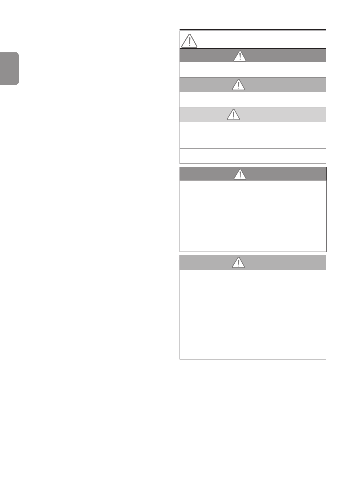
AVERTISSEMENT
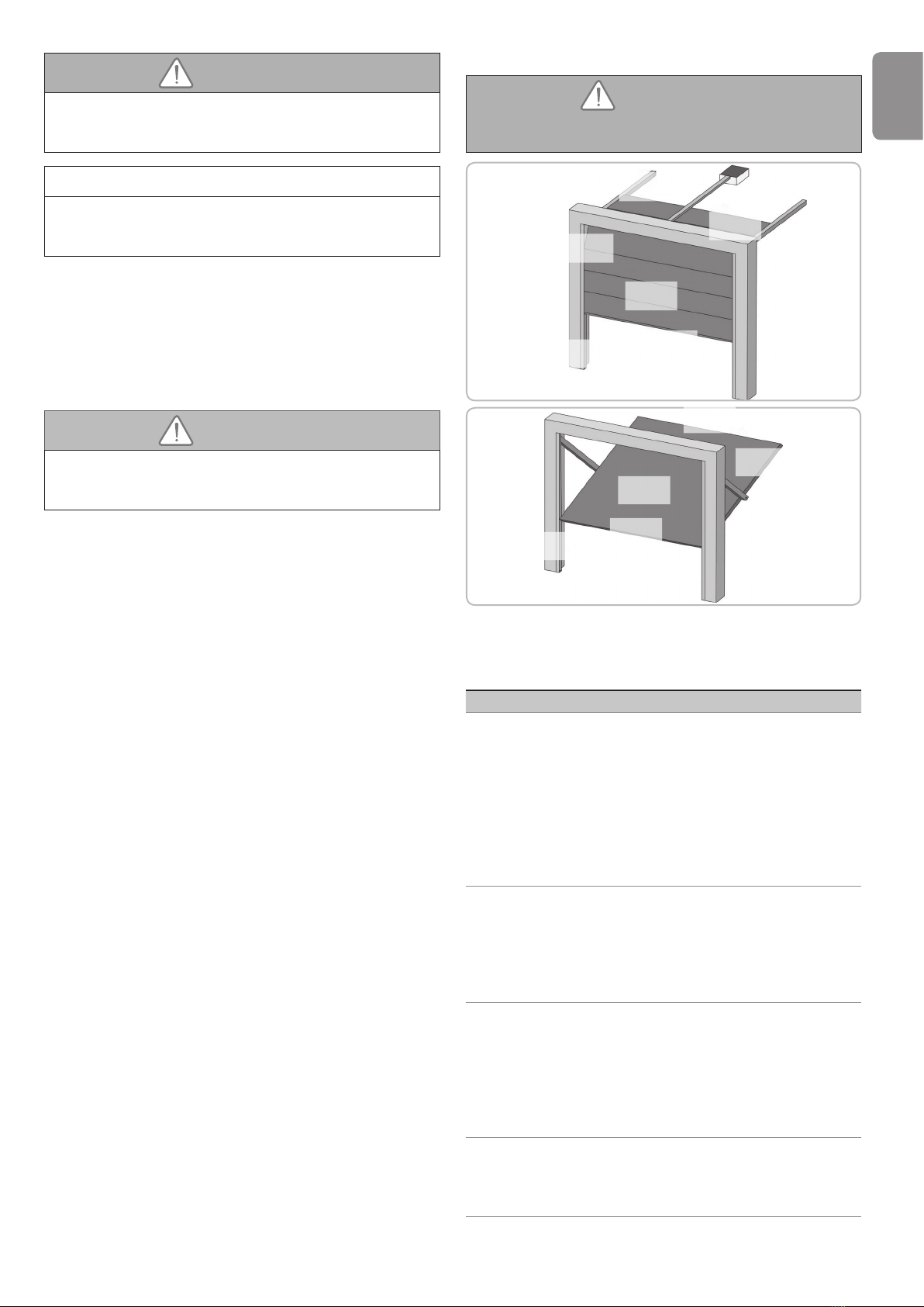
Prévention des risques - motorisation de porte de
garage sectionnelle / basculante à usage résidentiel
Zone 1
Zone 2
Zone 3
Zone 4
Zone 5
Zone 4
Zone 1
Zone 2
Zone 3
Zone 5
Zone 4
Zones à risque : Quelles mesures prendre pour les
éliminer ?
RISQUES SOLUTIONS
ZONE 1
Risque d’écrasement
à la fermeture entre le
sol et le bord inférieur
du tablier
Détection d’obstacle intrinsèque
à la motorisation.
Valider impérativement que
la détection d’obstacle est
conforme à l’annexe A de la
norme EN 12 453).
Dans le cas de fonctionnement à
refermeture automatique installer
des cellules photoélectriques.
ZONE 2*
Risque d’écrasement
à la fermeture entre
le linteau et le bord
supérieur du tablier
Détection d’obstacle intrinsèque
à la motorisation.
Valider impérativement que
la détection d’obstacle est
conforme à l’annexe A de la
norme EN 12 453).
ZONE 3*
Risque de coupure et
de coincement entre
les panneaux du tablier
dans les jours dont la
dimension varie entre
8mm et 25mm
Supprimer tous les points
d’accrochage et tous les bords
coupants de la surface du tablier
Supprimer tout jour de dimension
≥ 8 mm ou ≤ 25 mm
ZONE 4*
Risque de coincement
entre les rails de
roulement et les galets
Supprimer tous les bords
coupants des rails de guidage
Supprimer tout jour ≥ 8 mm
entre les rails et les galets
FR
GM600
4 Copyright © 2015 Simu SAS. All rights reserved
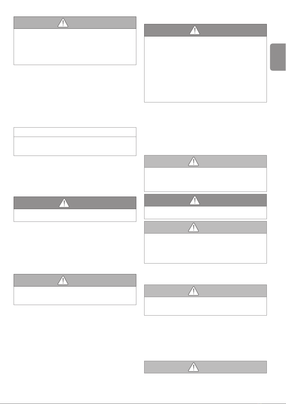
ZONE 5*
Risque d’écrasement
entre les bords
secondaires et les
parties xes attenantes
Détection d’obstacle intrinsèque
à la motorisation.
Valider impérativement que
la détection d’obstacle est
conforme à l’annexe A de la
norme EN 12 453).
* Pour les zones 2, 3, 4 et 5, aucune protection n’est requise
si la porte est à commande maintenue ou si la hauteur de la
zone dangereuse est supérieure à 2,5 m par rapport au sol
ou à tout autre niveau d’accès permanent.
2 - DESCRIPTION DU PRODUIT
2.1 Composition - Fig. 1
Rep. Nombre Désignation
1 1 Tête moteur
2 1 Trappe
3 1 Chape linteau
4 1 Chape porte
5 2 Patte de xation plafond
62Patte de xation tête moteur
7 1 Dispositif de débrayage manuel
8 1 Bras de liaison
91Butée n de course
10 4 Vis auto-perceuse TCB-H 4,2x13 zn
11 1 Cordon d’alimentation
12 4 Vis rondelle TH10 M8x12 zn
13 2 Vis TH M8x16 zn
14 6Ecrou HU8
15 2 Axe
16 2 Circlips
17 4 Vis auto-formeuse Ø 4x8
18a 1 Rail monobloc
18b 1 Rail en 2 parties
18b1 1 Manchon
18b2 8 Vis auto-formeuse Ø 4x8
19 2 Télécommande 4 canaux TSA+
20 1 Ampoule 24V 21W type BA15s
21 2 Coussinets de maintien de chaîne
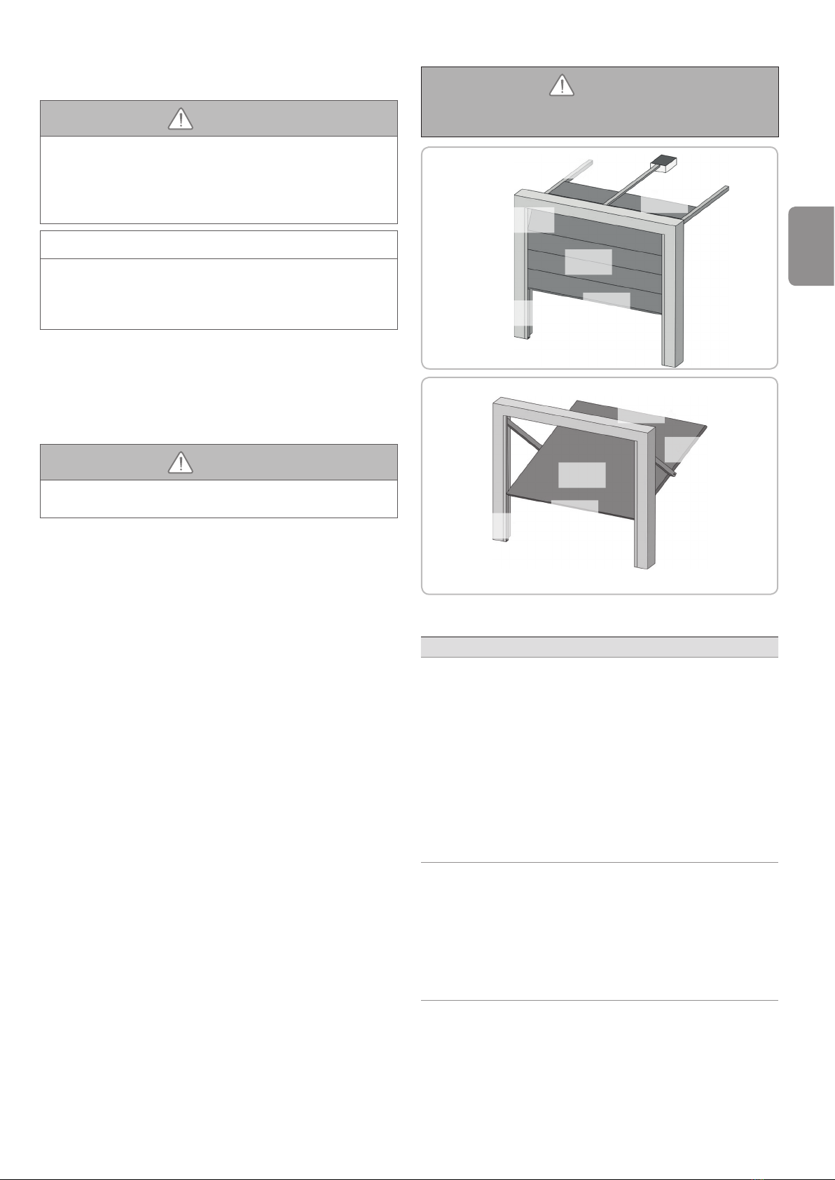
2.2 Domaine d’application - Fig. 2
Cette motorisation est exclusivement destinée à l’équipement d’une porte de
garage pour un usage résidentiel.
Types de portes (Fig.2)
La motorisation GM600 est prévue pour motoriser :
A : porte basculante débordante.
B : porte sectionnelle :
- si le prol supérieur du panneau est particulier, utiliser “la chape de xation
pour porte sectionnelle” réf.: 9009390.
Dimensions portes (Fig. 2)
Les portes de garage jusqu’à 7 m² de surface peuvent être motorisées
Pour les hauteurs maximum de portes, la course du moteur peut-être
optimisée :
- En montant la tête moteur à 90° (Fig. 6- ).
- En xant la chape linteau au plafond avec un retrait par rapport au linteau de
200 mm max. (Fig. 4- )
- En recoupant le bras de liaison.
Nombre de cycles par heure : 20 cycles/heure répartis uniformément dans
l’heure
3 - INSTALLATION
Si la porte de garage est l’unique accès au garage, prévoir un dispositif de
débrayage extérieur (réf. 9015169).
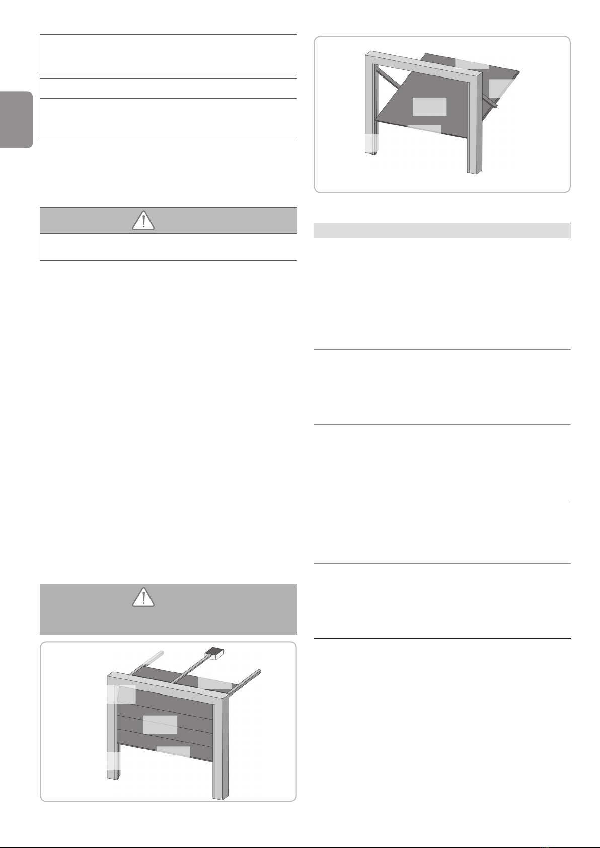
3.1 Hauteur d’installation - Fig. 3
Mesurer la distance “D” entre le point le plus haut de la porte et le plafond.
- Si “D” est comprise entre 35 et 200 mm, xer directement l’ensemble au
plafond.
- Si “D” est supérieure à 200 mm, xer l’ensemble de façon que la hauteur “H”
soit comprise entre 10 et 200 mm.
3.2 Étapes de l’installation - Fig. 4 à 14
Fixation de la chape linteau et de la chape porte (Fig. 4)
Dans le cas d’une installation directement au plafond (plafond collé), la chape
linteau peut être xé au plafond et si nécessaire avec un décalage par rapport
au linteau de 200 mm max. (Fig. 4- ).
Assemblage du rail en 2 parties (Fig. 5)
[1]. [2]. [3]. Déplier les 2 tronçons du rail.
Vérier que la chaîne ou la courroie n’est pas croisée.
[4]. Assembler les 2 tronçons du rail à l’aide du manchon.
[5]. Fixer l’ensemble à l’aide des 8 vis de xations.
[6]. Serrer l’écrou pour tendre la chaîne ou la courroie. Le caouctchouc écrasé
doit mesurer 18 et 20 mm.
Les vis de xation ne doivent pas rentrer dans le rail (ne pas percer).
Dans le cas d’une installation plafond collé, ne pas utiliser les vis de xation
du manchon.
Assemblage du rail à la tête moteur (Fig. 6)
Fixation de l’ensemble au plafond du garage (Fig. 7 à 9)
Fixation à la chape linteau (Fig. 7)
Fixation au plafond
Plafond collé : xation au plafond directement par l’intermédiaire du rail (Fig. 8).
Plafond décollé : xation au niveau de la tête moteur (Fig. 9)
Pour une xation intermédiaire ajustable le long du rail, ou une xation à une
dimension h comprise entre 250 mm et 550 mm, utiliser le kit xation plafond
réf.: 9015161 (Fig. 9 - ).
Fixation du bras à la porte et au chariot (Fig. 10)
Au cas où la poignée de débrayage est à une hauteur supérieure
à 1,80 m, il sera nécessaire de rallonger le cordon pour le rendre
accessible à tout utilisateur.
[1]. Débrayer le chariot à l’aide du dispositif de débrayage manuel.
[2]. Amener le chariot au niveau de la porte.
[3]. Fixer le bras à la chape porte et au chariot.
Réglage et fixation de la butée d’ouverture (Fig. 11)
[1]. Débrayer le chariot à l’aide du dispositif de débrayage manuel et amener
la porte en position ouverte.
Lors de cette manœuvre, vérier que le cordon du dispositif de
débrayage ne risque pas de s’accrocher par la suite à une partie
saillante d’un véhicule (par exemple, une galerie de toit).
Ne pas ouvrir la porte au maximum, mais positionner celle-ci de façon
qu’elle n’atteigne pas ses butées.
[2]. Positionner la butée contre le chariot et la xer sur le rail.
Montage des coussinets de maintien de chaîne (Fig. 12)
Cas des rails à chaîne uniquement.
Positionner chacun des coussinets dans le premier trou du rail à l’extérieur des
ns de courses.
Veiller à enfoncer au maximum le coussinet de façon que l’ergot de
positionnement dépasse à l’extérieur du rail.

FR
GM600
Copyright © 2015 Simu SAS. All rights reserved 5
Vérification de la tension de la chaîne ou de la courroie (Fig. 13)
Les rails sont livrés avec une tension pré-réglée et contrôlée. Si nécessaire,
ajuster cette tension.
Le caoutchouc ou le ressort de tension ne doit jamais être totalement
comprimé pendant le fonctionnement.
Raccordement électrique de l’alimentation (Fig. 14)
[1]. Monter l’ampoule.
[2]. Raccorder au secteur.
Le voyant B clignote 2 fois en continu pour indiquer que le moteur est en
attente d’auto-apprentissage.
Brancher le câble d’alimentation à une prise prévue à cet effet et
conforme aux exigences électriques.
4 - PROGRAMMATION
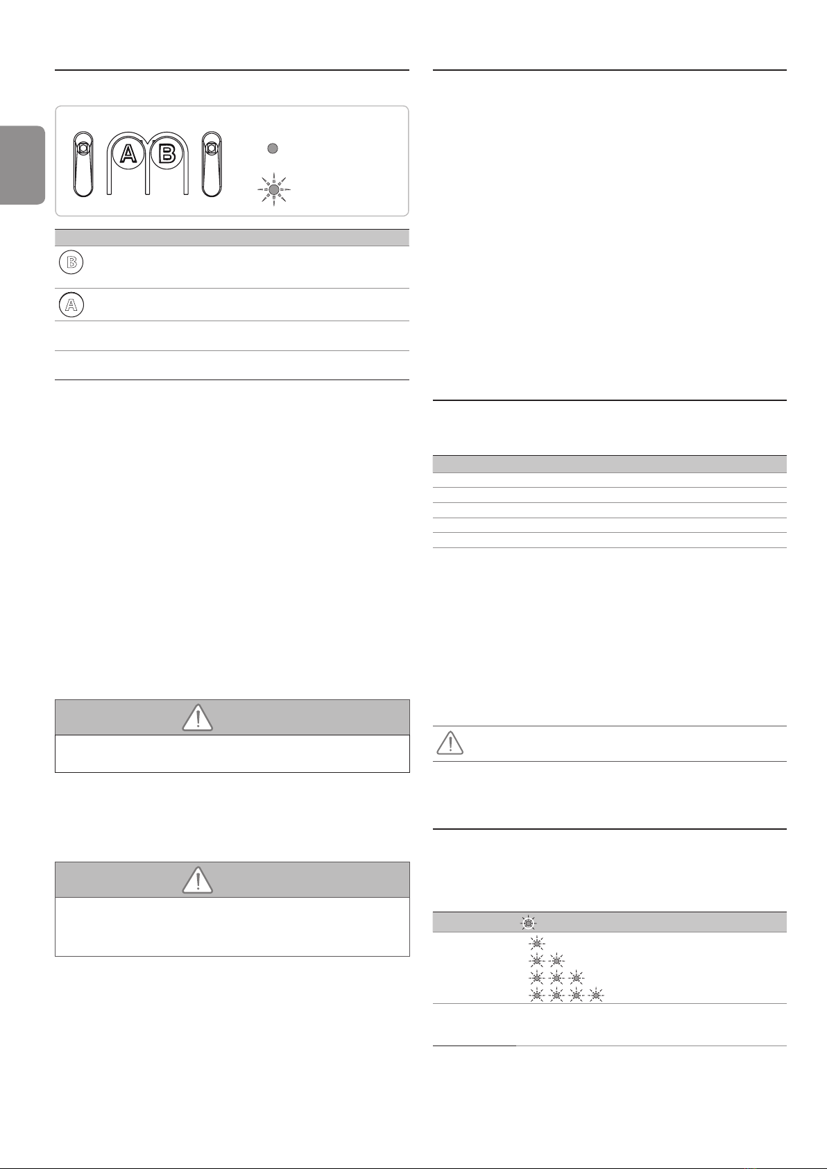
4.1 Description des touches de programmation
clignotant
éteint
Légende voyants
Touches Fonction
B
- Déclenchement de l’auto-apprentissage
- Mémorisation/suppression des télécommandes
- Modication de la valeur d’un paramètre
A
- Utilisation du mode marche forcée
- Sélection d’un paramètre
Voyant A - Voyant paramètre sélectionné
Voyant B - Voyant valeur de paramètre
- Voyant signalisation de défaut
4.2 Auto-apprentissage - Fig. 15
[1]. Commander le moteur avec la touche “A” pour que la navette de
transmission vienne s’embrayer sur le chariot et amener la porte en
position fermée :
- Maintenir l’appui sur la touche “A” pour provoquer le déplacement de
la navette.
- Relâcher la touche pour arrêter le déplacement.
- Maintenir à nouveau l’appui sur la touche “A” pour provoquer le
déplacement dans le sens opposé.
Relâcher la touche “A” avant tout forçage du moteur sur la porte.
[2]. Ajuster la position fermée à l’aide de la touche “A”.
Relâcher la touche “A” avant tout forçage du moteur sur la porte.
[3]. Appuyer sur “B” pour lancer le cycle d’auto-apprentissage.
La porte effectue un cycle Ouverture Fermeture complet.
- Si l’auto-apprentissage est correct, le voyant B s’éteint.
- Si le cycle d’auto-apprentissage ne s’est pas déroulé correctement, le
voyant B reste clignotant (2 clignotements).
Durant l’auto-apprentissage :
- Si la porte est en mouvement, l’appui sur n’importe quelle touche stoppe
le mouvement et interrompt l’auto-apprentissage.
Il est possible d’accéder au mode auto-apprentissage à tout moment y compris
lorsque le cycle d’auto-apprentissage a déjà été effectué.
Nota : Les télécommandes livrées dans le kit sont déjà mémorisées.
AVERTISSEMENT
d’obstacle est conforme à l’annexe A de la norme EN 12 453.
4.3 Verrouillage de l’accès aux paramètres (touche A)
- FIG. 16
Appuyer sur la touche A par impulsions successives jusqu’à ce que le
voyant A clignote 4 fois.
Appuyer une fois sur le bouton B :
- Le menu des paramètres (touche A) est verrouillé.
AVERTISSEMENT
Le non respect de cette consigne pourrait gravement blesser des
personnes, par exemple écrasées par la porte.
A ce niveau de l’installation, la motorisation GM600 est prête à
fonctionner.
5 - ESSAI DE FONCTIONNEMENT
5.1 Utilisation des télécommandes - Fig. 17
5.2 Fonctionnement de la détection d’obstacle - Fig.
18 et 19
Une détection d’obstacle durant la fermeture provoque la ré-ouverture de la
porte (Fig. 18).
Une détection d’obstacle durant l’ouverture provoque l’arrêt de la porte
(Fig. 19).
Vérier que la détection d’obstacle fonctionne lorsque la porte rencontre un
obstacle de 50 mm de hauteur placé sur le sol.
5.3 Fonctionnement de l’éclairage intégré
L’éclairage s’allume à chaque mise en route de la motorisation. Il s’éteint
automatiquement au bout de 30 secondes après la n du mouvement de la
porte. Une utilisation répétitive donnant lieu à un allumage continu de la lampe,
peut conduire à une extinction automatique due à une protection thermique.
5.4 Formation des utilisateurs
Former impérativement tous les utilisateurs à l’usage en toute sécurité de cette
porte (utilisation standard et principe de déverrouillage) et aux vérications
périodiques obligatoires.
6 - RACCORDEMENTS DES
PÉRIPHÉRIQUES
6.1 Description des différents périphériques - Fig. 20
Rep. Désignation
1 Feu orange
3 Contact à clé
4 Antenne
5 Batterie
6Cellules photoélectriques
6.2 Raccordement électrique des différents
périphériques - Fig. 20 à 21
Couper l’alimentation électrique du moteur avant toute intervention sur les
périphériques.
Schéma électrique général (Fig. 20)
Cellules photoélectriques (Fig. 21)
Lors de la mise en place des cellules, supprimer le pont réalisé entre les bornes
1 et 2.
Si suppression des cellules, il est impératif de refaire le pont entre
les bornes 1 et 2.

FR
GM600
6 Copyright © 2015 Simu SAS. All rights reserved
7 - PARAMÉTRAGE ET OPTIONS DE
FONCTIONNEMENT
7.1 Schéma général paramétrage - Fig.22
7.2
Exemple de programmation : réglage de la zone de ralentissement longue
(Fig. 23)
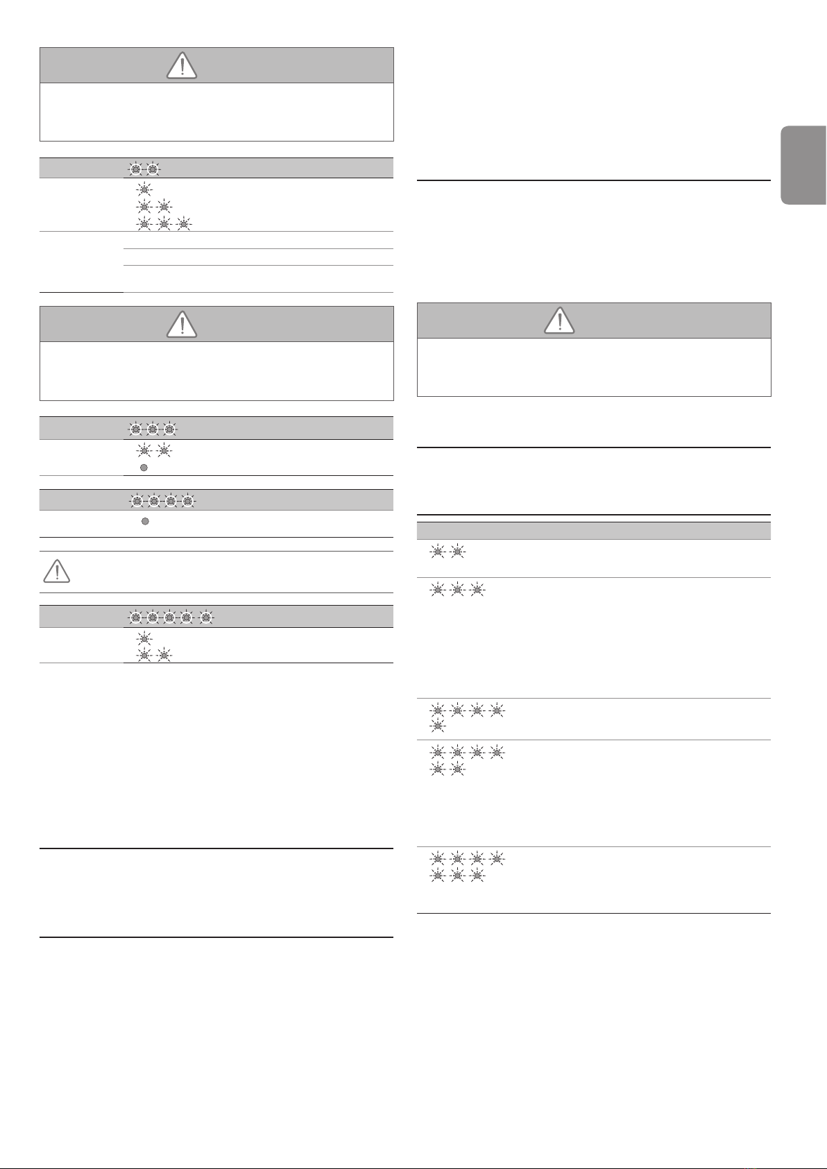
Voyant A Sensibilité de la détection d’obstacle
Voyant B 1 : très peu sensible
2 : peu sensible
3 : standard
4 : très sensible
AVERTISSEMENT
norme EN 12 453.
Le non respect de cette consigne pourrait gravement blesser des
personnes, par exemple écrasées par la porte.
Voyant A
Vitesse d’accostage en fermeture
Voyant B 1 : pas de ralentissement
2 : ralentissement court
3 : ralentissement long
Commentaires 1 : pas de ralentissement en n de fermeture.
2 : la vitesse est réduite durant les 20 derniers centimètres.
3 : la vitesse est réduite durant les 50 derniers centimètres.
AVERTISSEMENT
norme EN 12 453.
Le non respect de cette consigne pourrait gravement blesser des
personnes, par exemple écrasées par la porte.
Voyant A
Mode auto-apprentissage
Voyant B 2 : en attente auto-apprentissage
0 : l’auto-apprentissage est terminé
Voyant A
Verrouillage du menu des paramètres
Voyant B 0 : le menu des paramètres est verrouillé
En cas d’appui involontaire sur la touche B, passer à l’étape 10 pour
déverrouiller le menu des paramètres
Voyant A
Type d’alimentation
Voyant B 1 : alimentation secteur
2 : solaire
Mémorisation de la télécommande pour le fonctionnement en
«Ouverture totale» (Fig. 24)
Les télécommandes livrées dans le kit sont déjà mémorisées.
Il est possible de mémoriser jusqu’à 32 canaux de commandes.
L’exécution de cette procédure par un canal déjà mémorisé provoque
l’effacement de celui-ci.
Mémorisation d’une télécommande type Color ou similaire
(Fig. 25)
8 - FONCTIONNEMENTS PARTICULIERS
Voir livret utilisateur.
9 - EFFACEMENT DES TÉLÉCOMMANDES
ET DE TOUS LES RÉGLAGES
9.1 Suppression des télécommandes - Fig. 26
Appuyer sur la touche “B” jusqu’au clignotement de la lampe (7 s).
Provoque l’effacement de toutes les télécommandes mémorisées.
9.2 Réinitialisation de tous les réglages - Fig. 27
[1]. Appuyer 3 fois sur la touche “A” pour accéder au paramètre auto-
apprentissage.
[2]. Appuyer sur la touche “B” pour entrer en mode auto-apprentissage. Le
voyant B clignote 2 fois en continu.
[3]. Commander le moteur avec la touche “A” pour que la navette de
transmission vienne s’embrayer sur le chariot et amener la porte en
position fermée.
[4]. Appuyer sur “B” pour lancer le cycle d’auto-apprentissage.
La porte effectue un cycle Ouverture Fermeture complet.
- Si l’auto-apprentissage est correct, le voyant B s’éteint.
- Si le cycle d’auto-apprentissage ne s’est pas déroulé correctement, le
voyant B clignote 2 fois en continu.
10 - DÉVERROUILLAGE DU MENU DES
PARAMÈTRES FIG. 28
Nota:Silemenu desparamètresestverrouilléet qu’aucune télécommande
mémorisée n’est disponible, il est nécessaire de mémoriser une
[1]. Appuyer de façon maintenue sur la touche A du GM600.
[2]. Sans relâcher la touche A, faire un appui sur une touche d’une
télécommande déjà mémorisée. La lampe du GM600 s’allume brièvement
pour indiquer que le déverrouillage est effectif.
[3]. Relâcher la touche A.
AVERTISSEMENT
utilisateurs.
Le non respect de cette consigne pourrait gravement blesser des
personnes, par exemple écrasées par la porte.
11 - REMONTAGE DE LA TRAPPE DU
CAPOT - FIG. 29
Monter la trappe du capot.
12 - DIAGNOSTIC
Voyant B Que faire ?
2 Moteur en attente
auto-apprentissage Lancer l’auto-apprentissage
3 Défaut cellules Vérier qu’aucun obstacle ne
provoque une détection des
cellules.
Vérier le câblage des
cellules ou faire un pont entre
les bornes 1 et 2 si pas de
cellules installées.
Vérier le bon alignement des
cellules.
5
Sécurité thermique du
moteur Laisser le moteur refroidir
jusqu’à ce que le défaut
disparaisse.

FR
GM600
Copyright © 2015 Simu SAS. All rights reserved 7
6
Défaut circuit mesure
courant moteur ou
défaut capteur
Couper l’alimentation
électrique (secteur et batterie
de secours), patienter
quelques minutes puis re-
brancher l’alimentation.
Effectuer un cycle d’auto-
apprentissage. Si le défaut
persiste, contacter l’assistance
technique Simu.
7
Puissance maximum
délivrable par le moteur
atteinte durant la phase
d’auto-apprentissage
Produit en limite de
fonctionnement.
13 - CARACTÉRISTIQUES TECHNIQUES
CARACTÉRISTIQUES GÉNÉRALES
Alimentation secteur 230 V - 50 Hz
Puissance maxi
consommée
Veille 4 W
Fonctionnement 120 W
Force de traction maxi 600 N
Utilisation
Nombre de cycles Ouverture/
Fermeture par jour
Max 20 cycles par jour testé pour
10000 cycles
Vitesse maximale 14 cm/s
Interface de programmation 2 boutons - 2 voyants
Conditions climatiques d’utilisation - 20 ° C / + 60 ° C - interieur sec IP
20
Fins de course Butée mécanique à l’ouverture
Électronique à la fermeture : position
de fermeture mémorisée
Isolation électrique Classe 2 : double isolation
Éclairage intégré 24 V / 21 W ; douille BA15s
Fréquence radio 433,42 MHz
< 10 mW
Nombre de canaux mémorisables 32
CONNEXIONS
Entrée sécurité Type Contact sec : NF
Compatibilité Cellules photoélectriques TX/RX
Entrée de commande laire Contact sec : NO
Sortie feu orange Sortie clignotante pour feu orange :
24 V - 15 W
Sortie alimentation accessoires 24 V - 500 mA max
Entrée antenne déportée Oui : compatible antenne RTS
(Réf. 9015167)
Entrée batterie de
secours
Oui : compatible pack batterie
(Réf. 9015168)
Autonomie 24 heures ; 5 à 10 cycles suivant
porte
Temps de charge 72 h
FONCTIONNEMENT
Mode marche forcée Par appui maintenu sur la touche “A”
Temporisation d’éclairage (après
mouvement) Fixe : 30 s
Préavis feu orange 2 s automatique si feu connecté
Fonctionnement
entrée de sécurité
En fermeture Réouverture totale
Avant ouverture
(ADMAP) Avec
Détection d’obsacle intégrée Sensibilité réglable : 4 niveaux
Fonctionnement en cas de détection
d’obstacle Réouverture totale
Démarrage progressif Oui
Vitesse d’ouverture Fixe : 14 cm/s (max.)
Vitesse de fermeture Fixe : 12 cm/s (max.)
Vitesse d’accostage en fermeture Programmable : pas de ralentissement,
zone de ralentissement courte (30 cm),
zone de ralentissement longue (50 cm)
13.1 Encombrements
Longueur hors tout : 3154,6
171 mini 140
63,7
125
147,1
152,7
Longueur hors tout : 3127,6
Course utile : 2555
Fixation : 2981,7
Rail : 2900
Rail : 2900
6533,5
119,6
114 173
173
86,5
173
113,5
113,5
269,7
269,7
GM600
1 Copyright © 2015 Simu SAS. All rights reserved
EN
1 - SAFETY INSTRUCTIONS
This symbol indicates a danger, the different
degrees of which are described below.
DANGER
Indicates a danger which may result in immediate death
or serious injury
WARNING
Indicates a danger which may result in death or serious
injury
PRECAUTION
Indicates a danger which may result in minor or
moderate injury
ATTENTION
Indicates a danger which may result in damage to or
destruction of the product
DANGER
The motorisation must be installed and adjusted by
a professional motorisation and home automation
installer, in compliance with the regulations of the
country in which it is to be used.
To comply with the safety requirements in the standards
EN 13241-1, EN 12445 and EN 12453, it is essential to
follow this manual during the installation process.
Non-observance of these instructions can result in
serious injury to persons, e.g. when trapped by a
door.
WARNING
1.1 Caution - Important safety instructions
For reasons of personal safety, it is important to follow
all the instructions, as incorrect installation can lead to
serious injury. Retain these instructions.
The installer must imperatively instruct all end-users to
warranty a safe usage of the motorisation according to
the user manual.
The user manual and installation manual must be given
to the end-user. The installer must explicitly inform the
end-user that installation, adjustment and maintenance
of the motorisation must be performed by a professional
motorisation and home automation installer.
1.2 Introduction
> Important information
This product is a motorisation for vertically or horizontally
opening garage doors, for residential use as dened in
standard EN 60335-2-95 and EN 60335-2-103, with which
it complies. The main purpose of these instructions is to
satisfy the requirements of the aforementioned standards
and to ensure the safety of equipment and persons.
CONTENTS
Translated version of the installation manual
1 - SAFETY INSTRUCTIONS 1
1.1 Caution - Important safety instructions 1
1.2 Introduction 1
1.3 Preliminary checks 2
1.4 Electrical installation 2
1.5 Safety instructions relating to installation 2
1.6 Regulations 3
1.7 Assistance 3
1.8 Danger zones 3
2 - PRODUCT DESCRIPTION 4
2.1 Product components - Fig. 1 4
2.2 Area of application - Fig. 2 4
3 - INSTALLATION 4
3.1 Height of the installation - Fig. 3 4
3.2 Information about the various installation stages - Fig. 4 to 14 4
4 - PROGRAMMING 5
4.1 Description of the programming buttons 5
4.2 Auto-programming - Fig. 15 5
4.3 Locking access to the parameters (button A) -
FIG. 16 5
5 - OPERATING TEST 5
5.1 Using the remote controls - Fig. 17 5
5.2 Obstacle detection operation - Fig. 18 and 19 5
5.3 Integrated lighting operation 5
5.4 End-users training 5
6 - CONNECTING ADDITIONAL DEVICES 5
6.1 Description of the various additional devices - Fig. 20 5
6.2 Electrically connecting additional devices - Fig. 20 to 21 5
7 - PARAMETER SETTING AND OPERATING
OPTIONS 5
7.1 General parameter-setting diagram - Fig.22 5
7.2 Meaning of different parameters 5
8 - SPECIFIC OPERATION 6
9 - CLEARING THE REMOTE CONTROLS AND ALL
SETTINGS 6
9.1 Clearing the remote controls - Fig. 26 6
9.2 Reinitialising all settings - Fig. 27 6
10 - UNLOCKING THE PARAMETERS MENU - FIG. 28 6
11 - REFITTING THE COVER FLAP - FIG. 29 6
12 - DIAGNOSTICS 6
13 - TECHNICAL DATA 7
13.1 Dimensions 7
GM600
Copyright © 2015 Simu SAS. All rights reserved 2
EN
WARNING
Any use of this product outside the scope of application
described in this manual is prohibited (see "Scope of
application" paragraph in the installation manual).
The use of any accessories or components not validated
by Simu is prohibited - safety of persons won’t be
ensured.
Simu cannot be held liable for damages resulting from non
compliance with the instructions of this manual.
In case of any doubts when installing the motorisation, or
to obtain additional information, consult the website www.
simu.com.
The instructions may be modied if and when there is a
change to the standards or to the motorisation.
1.3 Preliminary checks
> Installation environment
ATTENTION
Do not spray water onto the motorisation.
Do not install the motorisation in an explosive
environment.
> Condition of the door to be motorised
Before installing the motorisation, check that:
- the door is in good mechanical condition
- the door is correctly balanced
- the door can be opened and closed properly using a force
of less than 150 N.
DANGER
CAUTION: It is dangerous to perform any operation on
the door springs (the door may fall).
Check:
- The door mountings are in good condition.
- The structures of the garage (walls, lintel, partitions,
ceiling, etc.) enable the motorisation to be xed securely.
Strengthen these if necessary.
>
Make sure the parts of the door do not encroach onto the
pavement or public thoroughfare.
WARNING
If the garage door is tted with a wicket door, the door
must be equipped with a system that prevents it from
moving when the wicket door is not in the safety position.
1.4 Electrical installation
DANGER
The installation of the power supply must comply
with the standards in force in the country in which the
motorisation is installed, and must be carried out by
qualied personnel.
The electric line must be exclusively reserved for the
motorisation and equipped with protection, comprising:
- a 10 A fuse or breaker,
- a differential type device (30 mA).
An all-pole supply cut-off device must be provided.
It is recommended that you t a lightning conductor
(maximum residual voltage 2 kV).
> Cable feed
Underground cables must be equipped with a protective
sheath with a sufcient diameter to contain the motor
cable and the accessories cables.
For overground cables, use a cable grommet that will
withstand the weight of vehicles.
1.5 Safety instructions relating to installation
WARNING
Before installing the motorisation, remove any
unnecessary cords or chains and deactivate any
locking device (bolt) which is not required for motorised
operation.
DANGER
Do not connect the motorisation to a power source
(mains, battery or solar) before installation is complete.
WARNING
Ensure that any danger zones (crushing, cutting,
trapping) between the driven part and the surrounding
xed elements caused by the opening movement of the
driven part are avoided or indicated on the installation
(see the section “Danger zones”).
Permanently afx the crushing warning labels near to
any xed control devices, and so that they are extremely
visible to the end-user.
WARNING
Modifying one of the elements provided in this kit or
using an additional element not recommended in this
manual is strictly prohibited.
Monitor the door as it moves and keep people away from
it until installation is complete.
Do not use adhesive to secure the motorisation.
Install the internal manual back release device at a height
of less than 1.8 m.
Permanently afx the label concerning the manual back
release device near to its mobile component.
WARNING
GM600
3 Copyright © 2015 Simu SAS. All rights reserved
EN
Take care when using the manual back release device
as an open door can suddenly fall off if the springs are
weak, broken, or incorrectly balanced.
ATTENTION
Install any xed control device at a height of less than
1.5 m and within sight of the door, but away from moving
parts.
After installation, ensure that:
- the mechanism is correctly adjusted
- the manual back release device is operating correctly
- the motorisation changes direction when the door
encounters an object 50 mm high on the ground.
WARNING
For operation in automatic mode or remote control,
photoelectric cells must be installed.
For operation in automatic mode, or if the garage door
faces a public road, an orange light type signalling device
may be required to comply with the regulations in the
country in which the motorisation is installed.
> Clothing precautions
Take off any jewellery (bracelet, chain, etc.) during
installation.
For manoeuvring, drilling and welding operations, wear
appropriate protection (special glasses, gloves, ear
protection, etc.).
1.6 Regulations
SIMU declares that this product
GM600
complies with the essential requirements of applicable
European directives.
The full text of the CE declaration of conformity is
available at the following website www.simu.com.
1.7 Assistance
You may encounter difculties or have questions when
installing your motorisation.
Do not hesitate to contact us; our specialists are on hand
to answer all your questions. Internet: www.simu.com
1.8 Danger zones
WARNING
Risk prevention - motorisation of sectional/up and
over garage door for residential usage
Zone 1
Zone 2
Zone 3
Zone 4
Zone 5
Zone 4
Zone 1
Zone 2
Zone 3
Zone 5
Zone 4
Risk zones: measures to be taken to eliminate risks
RISK SOLUTION
ZONE 1
Risk of crushing
between the ground
and the lower edge
of the door during
closing
Obstacle detection built into
the motorisation. It must be
imperatively checked that the
obstacle detection complies with
annex A of the standard EN 12
453.
For operation with automatic
closing, install photoelectric cells
(see installation manual)
ZONE 2*
Risk of crushing
between the lintel and
the upper edge of the
door during closing
Obstacle detection built into
the motorisation. It must be
imperatively checked that the
obstacle detection complies with
annex A of the standard EN 12
453.
ZONE 3*
Risk of cutting or
trapping between the
door panels in gaps
of between 8mm and
25mm
Eliminate all sticking points and
all sharp edges from the surface
of the door
Eliminate any gap ≥ 8 mm or
≤ 25 mm
ZONE 4*
Risk of trapping
between the roller rails
and bearings
Eliminate all sharp edges on the
guide rails
Eliminate any gap ≥ 8 mm
between the rails and the
bearings
ZONE 5*
Risk of crushing
between the
secondary edges and
adjoining xed parts
Obstacle detection built into
the motorisation. It must be
imperatively checked that the
obstacle detection complies with
annex A of the standard EN 12
453.
* For zones 2, 3, 4 and 5, no protection is required if the
door has continuous control or if the danger zone is more
than 2.5 m above the ground or any other permanent
access level.
GM600
Copyright © 2015 Simu SAS. All rights reserved 4
EN
2 - PRODUCT DESCRIPTION
2.1 Product components - Fig. 1
Key Number Description
1 1 Motor head
2 1 Flap
3 1 Lintel yoke
4 1 Door yoke
5 2 Ceiling mounting bracket
62 Motor head mounting bracket
7 1 Manual back release device
8 1 Connecting arm
91 End limit stop
10 4 TCB-H 4.2x13 zn self-tapping screws
11 1 Power supply cord
12 4 TH10 M8x12 zn washer screws
13 2 TH M8x16 zn screws
14 6HU8 nut
15 2 Shaft
16 2 Circlips
17 4 Thread-forming screws Ø 4x8
18a 1 Single unit rail
18b 1 2-part rail
18b1 1 Sleeve
18b2 8 Thread-forming screws Ø 4x8
19 2
TSA+ 4 channels remote controls
20 1 24V 21W bulb type BA15s
21 2 Chain bearings
2.2 Area of application - Fig. 2
This motorisation is exclusively intended for the equipement of a garage door
for residential use.
Types of door (Fig.2)
The GM600 motorisation is designed to motorise:
A : overhead door.
B : sectional door:
- if the upper prole of the panel is special, use the «mounting yoke for a
sectional door” part no.: 9009390.
Door dimensions (Fig. 2)
Garage doors up to a surface area of 7 m² can be motorised.
For doors which are maximum in height, the motor travel can be optimised:
- By mounting the motor head at 90° (Fig. 6- ).
- By xing the lintel yoke to the ceiling, setting it back a maximum of 200 mm in
relation to the lintel (Fig. 4- )
- By cutting the connecting arm.
Number of cycles per hour: 20 cycles/hour spread evenly throughout the
hour.
3 - INSTALLATION
If the garage door is the sole means of access to the garage, install an external
back release device (ref. 9015169).
3.1 Height of the installation - Fig. 3
Measure the distance “D” between the highest point of the door and the ceiling.
- If “D” is between 35 and 200 mm, secure the assembly directly to the ceiling.
- If “D” is greater than 200 mm, secure the assembly so that the height “H” is
between 10 and 200 mm.
3.2 Information about the various installation stages -
Fig. 4 to 14
Mounting the lintel yoke and door yoke (Fig. 4)
In the case of a door being installed directly on the ceiling (attached ceiling), the
lintel yoke may be xed to the ceiling and, if necessary, have an offset of 200
mm max in relation to the lintel. (Fig. 4- ).
Assembling the 2-part rail (Fig. 5)
[1]. [2]. [3]. Unfold the 2 sections of the rail.
Ensure that the chain or belt is not twisted.
[4]. Assemble the 2 sections of the rail using the sleeve.
[5]. Secure the assembly using 8 mounting screws.
[6]. Tighten the nut to tension the chain or belt. The compressed rubber must
measure between 18 and 20 mm.
The mounting screws must not penetrate the rail (do not drill).
In the case of an attached ceiling installation, do not use the sleeve mounting
screws.
Assembling the rail to the motor head (Fig. 6)
Mounting the assembly on the garage ceiling (Fig. 7 to 9)
Mounting the lintel yoke (Fig. 7)
Mounting to the ceiling
Attached ceiling: mounting directly to the ceiling using the rail (Fig. 8).
Detachable ceiling: mount the system at the motor head (Fig. 9)
For adjustable intermediate mounting along the rail, or mounting at a dimension
h between 250 mm and 550 mm, use the ceiling mounting kit,
part no.: 9015161 (Fig. 9 - ).
Mounting the arm to the door and carriage (Fig. 10)
In case the handle release system is positionned greater height
than 1,80 m, it will be necessary to lenghten the cord to make it
accessible to all end-users.
[1]. Release the carriage using the manual back release device.
[2]. Bring the carriage level with the door.
[3]. Secure the arm to the door yoke and carriage.
Adjusting and mounting the opening stop (Fig. 11)
[1]. Release the carriage using the manual back release device and move the
door to the open position.
At this step, make sure that the cord from the manual release system
could not be caught afterwards in a prominent part of the vehicule
(i.e. roofbars).
Do not open the door fully, but position it so that it does not reach its stops.
[2]. Position the stop against the carriage and secure it to the rail.
Mounting the chain bearings (Fig. 12)
For chain rails only.
Position each of the bearings in the rst hole in the rail, outside the end limits.
Ensure that the bearing is fully pushed in so that the positioning lug protrudes
past the outside of the rail.
Checking the tension of the chain or belt (Fig. 13)
The rails are supplied pre-tensioned and checked. If necessary, adjust this
tension.
The rubber must never be completely compressed during operation.
Connection to the electrical power supply (Fig. 14)
[1]. Fit the light.
[2]. Connect to the mains supply.
Warning light B ashes twice continuously to indicate that the motor is
waiting for auto-programming.
Connect the power supply cable to a socket provided for this purpose
and which complies with the electrical requirements.
GM600
5 Copyright © 2015 Simu SAS. All rights reserved
EN
4 - PROGRAMMING
4.1 Description of the programming buttons
ashing
off
Warning light legend:
Buttons Function
B
- Triggering of auto-programming
- Memorising/clearing the remote controls
- Modifying a parameter value
A
- Use of forced operating mode
- Selecting a parameter
Warning
light A - Parameter warning light selected
Warning
light B - Parameter value warning light
- Fault indicator warning light
4.2 Auto-programming - Fig. 15
[1]. Control the motor with button “A” so that the transmission shuttle is
engaged on the carriage and bring the door to the closed position:
- Keep pressing button “A” to cause the shuttle to move.
- Release the button to stop the movement.
- Press button “A” again to trigger movement in the opposite direction.
Release button “A” before forcing the motor on the door.
[2]. Adjust the closed position using button “A”.
Release button “A” before forcing the motor on the door.
[3]. Press “B” to launch the auto-programming cycle.
The door performs a complete Opening-Closing cycle.
- If the auto-programming is correct, warning light B goes out.
- If the auto-programming cycle was not successful, warning light B
continues to ash (2 ashes).
During auto-programming:
- If the door is moving, the movement is stopped and auto-programming
is interrupted if any of the buttons are pressed.
It is possible to access auto-programming mode at any moment including when
the auto-programming cycle has already been completed.
Note: The remote controls supplied in the kit have already been
memorised.
WARNING
At the end of installation, it must be checked that the obstacle detection
complies with annex A of the standard EN 12 453.
4.3 Locking access to the parameters (button A) -
FIG. 16
Press button A repeatedly until the indicator light A ashes 4 times.
Press button B once:
- The parameters menu (button A) is locked.
WARNING
Once installation is complete, the parameters menu must always be
locked to ensure the safety of users.
Non-observance of this instruction can result in serious injury to
persons, e.g. when trapped by a door.
At this stage of the installation, the GM600 motorisation is ready
to operate.
5 - OPERATING TEST
5.1 Using the remote controls - Fig. 17
5.2 Obstacle detection operation - Fig. 18 and 19
When an obstacle is detected during closing, the door re-opens (Fig. 18).
When an obstacle is detected during opening, the door will stop (Fig. 19).
Check that the obstacle detection function works when the door encounters a
50 mm high obstacle on the ground.
5.3 Integrated lighting operation
The lighting comes on each time the motorisation is switched on. When the
door stops moving, it goes off automatically after 30 seconds.
Repetitive use will cause the light to be lit constantly which may result in the
light being switched off automatically due to thermal protection.
5.4 End-users training
The end-users must be imperatively instruct to the safety use of this motorised
door (standard use and manual release principle) as well as to periodic and
compulsery checks.
6 - CONNECTING ADDITIONAL DEVICES
6.1 Description of the various additional devices -
Fig. 20
No. Description
1 Orange light
3 Key lock
4 Aerial
5 Battery
6Photoelectric cells
6.2 Electrically connecting additional devices - Fig. 20
to 21
Switch off the electrical supply to the motor before performing any operation on
the additional devices.
General electrical diagram (Fig. 20)
Photoelectric cells (Fig. 21)
When positioning the cells, remove the bridge created between terminals 1
and 2.
If cells are removed, it is essential to recreate the bridge between
terminals 1 and 2.
7 - PARAMETER SETTING AND
OPERATING OPTIONS
7.1 General parameter-setting diagram - Fig.22
7.2 Meaning of different parameters
Programming example: Adjusting the long slow zone (Fig. 23)
Warning light A Obstacle detection sensitivity
Warning light B 1 : very low sensitivity
2 : slightly sensitive
3 : standard
4 : very sensitive
Comments If this parameter is modied, the installer must check that
the limitation of forces complies with appendix A of the
standard EN 12 453.
GM600
Copyright © 2015 Simu SAS. All rights reserved 6
EN
WARNING
detection complies with annex A of the standard EN 12 453.
Non-observance of this instruction can result in serious injury to
persons, e.g. when trapped by a door.
Warning light A Coupling speed when closing
Warning light B 1 : no reduction in speed
2 : short reduction in speed
3 : long reduction in speed
Comments 1 : No reduction in speed at the end of closing.
2 : The speed is reduced during the last 30 centimetres.
3 : The speed is reduced during the last 50 centimetres.
WARNING
detection complies with annex A of the standard EN 12 453.
Non-observance of this instruction can result in serious injury to
persons, e.g. when trapped by a door.
Warning light A Auto-programming mode
Warning light B 2 : waiting for auto-programming
0 : self-learning is complete
Warning light A
Locking the parameters menu
Warning light B 0 : the parameters menu is locked
If button B is pressed, move on to step 10 to unlock the parameters
menu
Warning light A Power supply type
Warning light B 1 : Power supply
2 : Solar
Memorising the remote controls for operation in «Total opening»
mode (Fig. 24)
The remote controls supplied in the kit have already been memorised.
It is possible to memorise up to 32 control channels.
If this procedure is carried out using a channel which has already been
memorised, this channel will be cleared.
Memorising a Color type remote control or similar (Fig. 25)
8 - SPECIFIC OPERATION
See the user booklet.
9 - CLEARING THE REMOTE CONTROLS
AND ALL SETTINGS
9.1 Clearing the remote controls - Fig. 26
Press button “B” until the light ashes (7 secs).
Causes all memorised remote controls to be cleared.
9.2 Reinitialising all settings - Fig. 27
[1]. Press button “A” 3 times to access the auto-programming parameter.
[2]. Press button “B” to enter auto-programming mode. Warning light B
ashes twice continuously.
[3]. Control the motor with button “A” so that the transmission shuttle is
engaged on the carriage and brings the door to the closed position.
[4]. Press “B” to launch the auto-programming cycle.
The door performs a complete Opening-Closing cycle.
- If the auto-programming is correct, warning light B goes out.
- If the auto-programming cycle was not successful, warning light B
ashes twice continuously.
10 - UNLOCKING THE PARAMETERS MENU
- FIG. 28
Note: If the parameters menu is locked and no memorised remote control
[1]. Press and hold button A on the GM600.
[2]. Without releasing button A, press a button on a remote control which is
already memorised. The light on the GM600 comes on briey to indicate
that unlocking has taken place.
[3]. Release button A.
WARNING
Once the work being carried out by the professional is complete, the
parameters menu must always be locked to ensure the safety of users.
Non-observance of this instruction can result in serious injury to
persons, e.g. when trapped by a door.
11 - REFITTING THE COVER FLAP - FIG. 29
Fit the cover ap.
12 - DIAGNOSTICS
Warning light B Meaning Solution?
2 Motor waiting for auto-
programming
Start auto-programming
3 Cell fault Check that no obstacles
prevent the cells from
detecting.
Check the wiring of the cells
or create a bridge between
terminals 1 and 2 if no cells
are installed.
Check the correct alignment of
the cells.
5
Motor thermal
protection device Leave the motor to cool until
the fault disappears.
6
Motor current
measuring circuit fault
or sensor fault
Switch off the power supply
(mains and backup battery),
wait a few minutes then
reconnect the power supply.
Perform an auto-programming
cycle. If the fault remains,
contact Simu technical
assistance.
7
Maximum power
delivered by the motor
reached during the
auto-programming
phase
Product has reached
operating limit.

GM600
7 Copyright © 2015 Simu SAS. All rights reserved
EN
13 - TECHNICAL DATA
GENERAL SPECIFICATIONS
Power supply 230 V - 50 Hz
Max. power
consumption
Standby 4 W
operation 120 W
Max. tensile force 600 N
Operation
Number of Opening-Closing cycles
per day
20 cycles per day max. tested for
10,000 cycles
Maximum speed 14 cm/s
Programming interface 2 buttons - 2 warning lights
Climatic operating conditions 20°C / + 60°C - dry interior - IP 20
End limits Opening mechanical stop
Electronic when closing: stored
closing position
Electrical insulation Class 2: double-insulated
Integrated lighting 24 V / 21 W; BA15s socket
Radio frequency 433,42 MHz
< 10 mW
Number of storable channels 32
CONNECTIONS
Safety input Type Dry contact: NC
Compatibility TX/RX photoelectric cells
Wired control input Dry contact: NO
Orange light output Flashing output for orange light: 24 V
- 15 W
Accessories supply output 24 V - 500 mA max
Offset aerial input Yes: RTS antenna compatible (part
no.: 9015167)
Backup battery
input
Yes: battery pack compatible (part
no.: 9015168)
Battery life 24 hours; 5 to 10 cycles depending
on the door
Charging time: 72 hours
OPERATION
Forced operating mode By pressing and holding button “A”
Timed lighting (after movement) Set at 30 seconds
Orange light warning 2 secs automatic if light connected
Security entry
operation
When closing Total reopening
Before opening
(ADMAP) With
Integrated obstacle detection Adjustable sensitivity: 4 levels
Operation in the event of obstacle
detection Total reopening
Gradual starting Yes
Opening speed Fixed: 14 cm/s (max.)
Closing speed Fixed: 12 cm/s (max.)
Coupling speed when closing Programmable: no reduction in speed,
short slow zone (30 cm), long slow zone
(50 cm)
13.1 Dimensions
Overall Length : 3154,6
171 mini 140
63,7
125
147,1
152,7
Overall Length : 3127,6
Available travel : 2555
Fixation : 2981,7
Rail : 2900
Rail : 2900
6533,5
119,6
114173
173
86,5
173
113,5
113,5
269,7
269,7
GM600
Copyright © 2015 Simu SAS. All rights reserved 1
DE
1 - SICHERHEITSHINWEISE
Dieses Symbol weist auf eine Gefahr hin, deren
verschiedene Gefährdungsgrade nachstehend
beschrieben sind.
GEFAHR
Weist auf eine Gefahr hin, die sofort zu schweren bis
tödlichen Verletzungen führt.
WARNUNG
Weist auf eine Gefahr hin, die zu schweren bis tödlichen
Verletzungen führen kann.
VORSICHT
Weist auf eine Gefahr hin, die zu leichten bis mittel-
schweren Verletzungen führen kann.
BITTE BEACHTEN:
Weist auf eine Gefahr hin, die das Produkt beschädigen
oder zerstören kann.
GEFAHR
Die Garagentorantriebe dürfen nur von fachlich
Automatisierungen im Haustechnikbereich gemäß
den in dem jeweiligen Land der Inbetriebnahme
geltenden Vorschriften installiert und eingestellt werden.
Um den Sicherheitsvorschriften in den Normen EN
13241-1, EN 12445 and EN 12453 zu entsprechen,
ist es entscheidend wichtig, während des
Installationsprozesses die vorliegende Anleitung zu
beachten. Die Nichtbeachtung dieser Hinweise kann
zu schweren Verletzungen von Personen führen, z.B.
beim Einklemmen durch das Tor.
WARNUNG
1.1 Warnhinweis - Wichtige Sicherheitshinweise
Für die Gewährleistung der Sicherheit von Personen ist es
wichtig, dass jeder dieser Hinweise befolgt wird, da es bei
unsachgemäßer Installation zu schweren Verletzungen
kommen kann. Bewahren Sie diese Sicherheitshinweise
gut auf.
Um einen sicheren Betrieb der Garagentoranlage zu
gewährleisten, muss der Installateur den Endnutzer
unbedingt entsprechend der Bedienungsanleitung
instruieren. Dem Endkunden/Verwender muss die
Bedienungs- und Installationsanleitung zur Verfügung
gestellt werden. In jedem Fall muss ihm explizit erklärt
werden, dass Installation, Einstellung und Wartung des
Antriebsnur voneinemfürAntriebeundAutomatisierungen
im Haustechnikbereich fachlich qualizierten Installateur
ausgeführt werden dürfen.
1.2 Wichtige Informationen
Dieses Produkt ist ein Antrieb für vertikal oder horizontal
öffnende Garagentore im Wohnbereich gemäß den Normen
EN 60335-2-95 und EN 60335-2-103, mit denen es konform
ist. Zweck dieser Anleitung ist es, die Anforderungen der
genannten Normen zu erfüllen und somit die Sicherheit von
Sachen und Personen zu gewährleisten.
INHALT
Übersetzte Version der Installationsanleitung
1 - SICHERHEITSHINWEISE 1
1.1 Warnhinweis - Wichtige Sicherheitshinweise 1
1.2 Wichtige Informationen 1
1.3 Prüfungen vor der Installation 2
1.4 Elektroinstallation 2
1.5 Sicherheitshinweise zur Installation 2
1.6 EG-Konformität 3
1.7 Support 3
1.8 Gefahrenvermeidung 3
2 - PRODUKTBESCHREIBUNG 4
2.1 Bestandteile - Abb. 1 4
2.2 Anwendungsbereich - Abb. 2 4
3 - MONTAGE 4
3.1 Einbauhöhe - Abb. 3 4
3.2 Die einzelnen Schritte der Montage im Detail -
Abb. 4 bis 14 4
4 - PROGRAMMIERUNG 5
4.1 Beschreibung der Programmiertasten 5
4.2 Automatisches Einlernen - Abb. 15 5
4.3 Verriegelung des Zugangs auf die Parameter (Taste A) - Abb. 16 5
5 - FUNKTIONSTEST 5
5.1 Funktionstest - Abb. 17 5
5.2 Verwendung der Funkhandsender - Abb. 18 und 19 5
5.3 Betrieb der integrierten Beleuchtung 5
5.4 Unterrichtung des Endnutzers 5
6 - ANSCHLUSS VON PERIPHERIEGERÄTEN 5
6.1 Beschreibung der verschiedenen Peripheriegeräte - Abb. 20 5
6.2 Elektroanschluss der verschiedenen Peripheriegeräte - Abb. 20 bis 21 6
7 - EINSTELLUNG DER PARAMETER UND OPTIONALE
FUNKTIONSWEISEN 6
7.1 Allgemeines Einstellschema - Abb.22 6
7.2 Bedeutung der verschiedenen Parameter 6
8 - SONDERFUNKTIONEN 6
9 - LÖSCHEN DER FUNKHANDSENDER UND ALLER
EINSTELLUNGEN 6
9.1 Löschen von Funkhandsendern - Abb. 26 6
9.2 Reinitialisierung aller Einstellungen - Abb. 27 6
10 - ENTRIEGELUNG DES ZUGANGS AUF DIE
PARAMETER (TASTE A) - ABB. 28 6
11 - WIEDERMONTAGE DES DECKELS DES
ANTRIEBSGEHÄUSES - ABB. 29 6
12 - DIAGNOSE 7
13 - TECHNISCHE EIGENSCHAFTEN 7
13.1 Abmessungen 7

GM600
2 Copyright © 2015 Simu SAS. All rights reserved
DE
WARNUNG
Jede Verwendung des Produkts für Anwendungen,
die nicht in dieser Anleitung beschrieben sind, ist
untersagt (siehe Abschnitt „Anwendungsbereich“ der
Installationsanleitung).
Die Verwendung von Zubehör oder Ersatzteilen, die von
Simu nicht freigegeben sind, ist aus Sicherheitsgründen
nicht zulässig.
Simu haftet nicht für die Folgen (Schäden, Fehler oder
Störungen), die sich aus der Nichtbeachtung dieser
Anleitung ergeben.
Wenn bei der Installation des Antriebs Fragen auftauchen
und für alle weitergehenden Informationen, steht die
Internetseite www.simu.com zur Verfügung.
Diese Anleitung kann im Falle von Änderungen der
Normen oder des Antriebs jederzeit geändert werden.
1.3 Prüfungen vor der Installation
Installationsumgebung
BITTE BEACHTEN:
Vermeiden Sie, dass Wasser auf den Antrieb kommt.
Der Antrieb darf nicht in einer explosionsgefährdeten
Umgebung installiert werden.
Zustand des mit dem Antrieb zu bewegenden Tors
Stellen Sie vor der Montage des Antriebs sicher, dass:
- das Tor in gutem mechanischem Zustand ist
- das Tor richtig eingestellt ist
- sich das Tor mühelos mit einer Kraft von weniger als
150 N öffnen und schließen lässt.
GEFAHR
WARNHINWEIS: Es ist gefährlich, Arbeiten an den
Federn des Tores vorzunehmen (Absturz des Tors).
Vergewissern Sie sich, dass:
- die Befestigungen des Tors in ordentlichem Zustand sind
- die Struktur der Garage (Mauern, Sturz, Wände, Decke...)
es zulassen, den Antrieb sicher zu befestigen.
Bei Bedarf entsprechend verstärken.
Technische Daten des mit dem Antrieb zu bewegenden Tors
Vergewissern Sie sich, dass keine Teile des Tors in
Gehwege oder sonstige öffentliche Bereiche ragen.
WARNUNG
Wenn das Garagentor mit einer Schlupftür ausgerüstet
ist, muss das Tor mit einem System versehen sein, das
verhindert, dass sich die Schlupftür bewegen kann, wenn
sie nicht in abgesicherter Position ist.
1.4 Elektroinstallation
GEFAHR
Die Elektroinstallation muss unter Beachtung der im
jeweiligen Land der Inbetriebnahme gültigen Normen von
einer Elektrofachkraft ausgeführt werden
Die Anschlussleitung darf nur den Antrieb versorgen und
muss wie folgt abgesichert sein:
- Durch eine Sicherung oder einen Sicherungsautomaten
10 A,
- durch eine Fehlerstromsicherung (30 mA).
Die Trennung vom Stromnetz muss alle Pole erfassen.
Die Installation eines Blitzschutzes wird empfohlen (mit
Restspannung max. 2 kV).
Kabelführung
In der Erde verlegte Kabel müssen in einem Schutzrohr
verlegt werden, dessen Durchmesser groß genug ist, um
die Kabel des Antriebs und der Zubehörteile aufnehmen zu
können.
Kabel, die nicht in der Erde verlegt werden, müssen in
einem Kabelkanal geführt werden, der für das Überfahren
mit Fahrzeugen ausgelegt ist.
1.5 Sicherheitshinweise zur Installation
Warnung
Entfernen Sie vor der Montage des Antriebs alle
überüssigen Seile und Ketten und entsichern Sie alle
Verriegelungsvorrichtungen (Schlösser), die für den
motorisierten Betrieb des Tors nicht nötig sind.
GEFAHR
Stellen Sie den Stromanschluss (Netz, Batterie oder
Solar) erst nach Abschluss der Montage her.
WARNUNG
Stellen Sie sicher, dass im Bereich zwischen den
sich bewegenden Teilen der Toranlage und den
fest installierten, beim Öffnen oder Schließen keine
Gefahrenzonen entstehen können (Verletzungen durch
Quetschen, Scheren oder Klemmen) oder an der Anlage
entsprechend darauf aufmerksam gemacht wird (siehe
das Kapitel „Gefahrenvermeidung“).
Befestigen Sie Schilder, die vor der Quetschgefahr
warnen, dauerhaft in der Nähe fest installierter
Steuergeräte und deutlich sichtbar für die Endnutzer.
WARNUNG
Die in diesem Kit gelieferten Bauteile dürfen auf keinen
Fall verändert oder zusätzliche Komponenten verwendet
werden, die nicht in dieser Anleitung vorgesehen sind.
Behalten Sie das Tor im Auge, während es sich bewegt,
und halten Sie alle Personen bis zum Abschluss der
Installation fern.
Der Antrieb darf nicht mit Klebstoffen befestigt werden.
Installieren Sie die Vorrichtung zur manuellen
Notentriegelung auf der Innenseite in einer Höhe von
weniger als 1,8 m.
GM600
Copyright © 2015 Simu SAS. All rights reserved 3
DE
Befestigen Sie das Schild mit Hinweisen zur manuellen
Notentriegelung dauerhaft in der Nähe des beweglichen
Teils der Vorrichtung.
WARNUNG
Seien Sie bei der Benutzung der
Notentriegelungsvorrichtung vorsichtig, denn das
Tor kann schnell nach unten fallen, wenn die Federn
schwach oder gebrochen sind, oder wenn das Tor falsch
eingestellt ist.
BITTE BEACHTEN:
Alle fest installierten Betätigungsvorrichtungen dürfen nur
in einer Höhe von höchstens 1,5 m und im Sichtbereich
des Tors, jedoch fern von beweglichen Teilen montiert
werden.
Vergewissern Sie sich nach der Montage, dass:
- der Mechanismus richtig eingestellt ist
- die Vorrichtung zur manuellen Notentriegelung ordnungs-
gemäß funktioniert
- der Antrieb die Richtung wechselt, wenn das Tor auf ein
50 mm hohes Objekt trifft, das auf dem Boden liegt.
WARNUNG
Bei Automatikbetrieb oder bei Fernbedienung ohne
Sichtkontakt muss eine Lichtschranke installiert werden.
Im Fall des Automatikbetriebs oder, wenn das
Tor auf einen öffentlichen Bereich öffnet, können
Rechtsvorschriften des Landes, in dem der Antrieb
eingesetzt wird, die Installation einer gelben Signalleuchte
verlangen.
> Vorsichtshinweise zur Kleidung
Legen Sie vor der Montage alle Schmuckstücke ab
(Armband, Kette und andere).
Tragen Sie beim Bewegen der Teile, bei Bohr- und
Schweißarbeiten eine geeignete Sicherheitsausrüstung
(Schutzbrille, Handschuhe, Gehörschutz etc.).
1.6 EG-Konformität
Wir, SIMU, erklären, dass dieses Produkt
GM600
mit den grundlegenden Anforderungen der einschlägigen
europäischen Richtlinien, insbesondere mit den
Richtlinien 2014/53/EG und 2006/42/EG konform ist. Eine
Konformitätserklärung ist unter der Internetadresse www.
simu.com/ verfügbar.
1.7 Support
Bei Schwierigkleiten während der Installation Ihres Antrieb
oder wenn Sie Fragen hierzu haben, zögern Sie bitte
nicht, sich an uns zu wenden: Unsere Fachleute stehen
Ihnen gern zur Verfügung. Internet: www.simu.com.
1.8 Gefahrenvermeidung
WARNUNG
Gefahrenvermeidung - Antrieb von Sektional- und
Kipptoren im Bereich Wohnnutzung
Zone 1
Zone 2
Zone 3
Zone 4
Zone 5
Zone 4
Zone 1
Zone 2
Zone 3
Zone 5
Zone 4
Gefahrenzonen: Wie können Sie beseitigt werden?
GEFAHREN LÖSUNGEN
ZONE 1
Quetschgefahr beim
Schließen zwischen
Boden und Unterkante
des Torblatts
Hinderniserkennung durch den
Antrieb. Es muss unbedingt
geprüft und festgestellt
werden, dass die Grenzwerte
der Betriebskräfte und
Reversierungszeiten gemäß
Anhang A der Norm EN 12 453
eingehalten sind. Zur Installation
einer Lichtschranke, wenn das
Tor automatisch schließt, siehe
Installationsanleitung
(siehe 6.2 + Abb. 21).
ZONE 2*
Quetschgefahr beim
Schließen zwischen
Sturz und Oberkante
des Torblatts
Hinderniserkennung durch den
Antrieb. Es muss unbedingt
geprüft und festgestellt
werden, dass die Grenzwerte
der Betriebskräfte und
Reversierungszeiten gemäß
Anhang A der Norm EN 12 453
eingehalten sind.
GM600
4 Copyright © 2015 Simu SAS. All rights reserved
DE
ZONE 3*
Gefahr von Schnitt-
und Klemmver-
letzungen in den
Zwischenräumen der
Torsegmente, wenn
deren Breite zwischen
8mm und 25 mm
beträgt
Am Tor alle Punkte beseitigen,
an denen man hängen bleiben
kann, und alle scharfen Kanten
am Torblatt entfernen.
Alle Zwischenräume mit
Breiten ≥ 8 mm oder ≤ 25 mm
beseitigen.
ZONE 4*
Gefahr des Ein-
klemmens zwischen
den Laufschienen und
den Rollen
Alle scharfen Kanten an den
Führungsschienen beseitigen
Jeden Abstand ≥ 8 mm
zwischen Schienen und Rollen
beseitigen.
ZONE 5*
Quetschgefahr
zwischen den
übrigen Kanten und
angrenzenden festen
Bauteilen
Hinderniserkennung durch den
Antrieb. Es muss unbedingt
geprüft und festgestellt
werden, dass die Grenzwerte
der Betriebskräfte und
Reversierungszeiten gemäß
Anhang A der Norm EN 12 453
eingehalten sind.
* Für die Zonen 2, 3, 4 und 5 sind keine Schutzvorrichtungen erforderlich,
wenn das Tor sich nur bei ständigem Steuerkontakt bewegt oder wenn die
Gefahrenzone mehr als 2,5 m über dem Boden oder über einer anderen,
ständig zugänglichen Ebene liegt.
2 - PRODUKTBESCHREIBUNG
2.1 Bestandteile - Abb. 1
Pos. Anzahl Bezeichnung
1 1 Antriebskopf
2 1 Deckel
3 1 Sturzgabel
4 1 Torgabel
5 2 Deckenbefestigungswinkel
62Befestigungswinkel Antriebskopf
7 1 Vorrichtung zur manuellen Entriegelung
8 1 Verbindungsarm
91 Endlagenanschlag
10 4 Selbstbohrende Schraube TCB-H 4,2x13 zn
11 1 Stromversorgungskabel
12 4 Schraube mit Unterlegscheibe TH10 M8x12 zn
13 2 Schraube TH M8x16 zn
14 6Mutter HU8
15 2 Welle
16 2 Sicherungsringe
17 4 Selbstschneidende Schraube Ø 4x8
18a 1 Einteilige Schiene
18b 1 Zweiteilige Schiene
18b1 1 Verbindungsprol
18b2 8 Selbstschneidende Schraube Ø 4x8
19 2 Funkhandsender TSA+ 4 Kanäle
20 1 Glühbirne 24 V / 21 W, Fassung BA15s
21 2 Kettentragprole
2.2 Anwendungsbereich - Abb. 2
Diese Motorisierung ist ausschließlich für die Ausstattung eines Garagentores
im Bereich der Wohnnutzung bestimmt.
Torart (Abb.2)
Der Antrieb GM600 ist vorgesehen für die Motorisierung:
A : Auskragendes Kipptor.
B : Sektionaltor:
- Verwenden Sie, wenn das oberste Prol des Panels sich unterscheidet, „die
Befestigungsgabel für Sektionaltore“ Artikelnr.: 9009390.
Torabmessungen (Abb. 2)
Es können Garagentore mit einer Fläche von bis zu 7 m² angetrieben werden.
Für sehr hohe Tore kann der Weg des Antriebs optimiert werden:
- Indem der Antrieb um 90° gedreht montiert wird (Abb. 6- ).
- Durch die Befestigung der Sturzgabel an der Decke, und zwar in einem
Abstand von bis zu 200 mm vom Sturz (Abb. 4- )
- Durch Verkürzung des Verbindungsarms.
Anzahl der Bewegungszyklen pro Stunde: 20 Zyklen/Stunde, gleichmäßig
über die Stunde verteilt.
3 - MONTAGE
Wenn das Garagentor der einzige Zugang zur Garage ist, muss eine Vorrichtung
zur Entriegelung von Außen vorgesehen werden (Teile-Nr. 9015169).
3.1 Einbauhöhe - Abb. 3
Ermitteln Sie das Maß „D“ zwischen dem höchsten Punkt des Tors und der
Decke.
- Wenn „D“ zwischen 35 und 200 mm ist, kann der Antrieb direkt an die Decke
montiert werden.
- Wenn „D“ größer als 200 mm ist, muss der Antrieb so montiert werden, dass
die Höhe „H“ zwischen 10 und 200 mm ist.
3.2 Die einzelnen Schritte der Montage im Detail -
Abb. 4 bis 14
Befestigung der Sturzgabel und der Torgabel (Abb. 4)
Wenn derAntrieb direkt an der Decke montiert wird, kann die Sturzgabel an der
decke und, wenn erforderlich, in einem Abstand von bis zu 200 mm vom Sturz
angebracht werden. (Abb. 4- ).
Zusammenbau der zweiteiligen Schiene (Abb. 5)
[1]. [2]. [3]. Entfalten Sie die 2 Abschnitte der Schiene.
Vergewissern Sie sich, dass die Kette oder der Riemen nicht über
Kreuz laufen.
[4]. Setzen Sie die 2 Abschnitte mit Hilfe des Verbindungsprols zusammen.
[5]. Verbinden Sie die Teile mit den 8 Befestigungsschrauben.
[6]. Ziehen Sie die Mutter fest, um die Kette oder den Riemen zu spannen. Der
zusammengedrückte Gummidämpfer sollte 18 - 20 mm dick sein.
Die Befestigungsschrauben dürfen nicht in die Schiene ragen (sie nicht
durchbohren).
Verwenden Sie bei einer Montage direkt an der Decke nicht die
Befestigungsschrauben des Verbindungsprols.
Montage der Schiene am Antriebskopf (Abb.6)
Befestigung des Antriebs an der Garagendecke (Abb.7 bis 9)
Befestigung der Sturzgabel (Abb.7)
Befestigung an der Decke
Direkt an der Decke: Befestigung direkt an der Decke über die Schiene (Abb. 8).
Mit Abstand zur Decke: Befestigung am Antriebskopf (Abb.9)
Verwenden Sie für eine in Längsrichtung der Schiene Justierbare
Befestigung oder eine Abhängung zwischen 250 mm und 550 mm den
Deckenbefestigungssatz, Artikelnr.: 9015161 (Abb. 9 - ).
Befestigung des Arms am Tor und am Schlitten (Abb. 10)
Achtung: Für den Fall, dass die Vorrichtung für manuelle
Notentriegelung höher als 1,80 m über dem Boden angebracht ist,
ist es notwendig, die Zugschnur zu verlängern, damit sie für alle
Nutzer erreichbar ist.
[1]. Entriegeln Sie den Schlitten mit Hilfe der manuellen
Entriegelungsvorrichtung.
[2]. Bewegen Sie den Schlitten zum Tor.
[3]. Befestigen Sie den Arm an der Torgabel und am Schlitten.
Other manuals for GM600
1
Table of contents
Languages:
Other Simu Garage Door Opener manuals


Popular Garage Door Opener manuals by other brands

FIRMADOOR
FIRMADOOR Remote Control Operator installation instructions

RIB
RIB AA30014M manual

SkyLink
SkyLink SG-18R user manual

Raynor
Raynor 3245RGD 1/3 HP owner's manual

Aprimatic
Aprimatic S-MATIC AC500 Mechanical installation, Use and Maintenance instructions

Chamberlain
Chamberlain 3265C 1/2 HP owner's manual

Cumberland
Cumberland FLX-5363 installation manual

Genius
Genius falcon m manual

Chamberlain
Chamberlain PowerLift Elite CS45EVO Installation and operating instructions

Chamberlain
Chamberlain LiftMaster Professional 5580 instructions

Chamberlain
Chamberlain ATS 211 owner's manual

Genie
Genie Garage Door Opener Programming manual


