Sinexcel PWS1-500KTL-NA User manual

Sinexcel
PWS1-500KTL-NA
Grid-Support Utility-Interactive Energy Storage Inverter


Sinexcel
PWS1-500KTL-NA
Grid-Support Utility-Interactive Energy Storage Inverter
User's Manual
Document Version: 20171225
Filed in: Sep 4, 2017
Applicable to: PWS1-500KTL-NA
Shenzhen Sinexcel Electric Co., Ltd. (“Sinexcel”) provides its customers with all-around technical support.
Users can contact Sinexcel’s local office or customer service center or directly contact Sinexcel
Headquarters.
Shenzhen Sinexcel Electric Co., Ltd.
All rights reserved. In case of any content change, it shall be without prior notice.
Shenzhen Sinexcel Electric Co., Ltd.
Website: www.sinexcel.com
Add: Building 6, Area 2, Baiwangxin High-tech Industrial Park, No. 1002, Songbai Road, Nanshan District,
Shenzhen
Postcode: 518055
Hotline: 0755-8651-1588
Fax: 0755-8651-3100
E-mail: service@sinexcel.com


Table of Contents
Chapter I Overview .......................................................................................... 1
Model definition ................................................................................................................................................................1
Symbolic interpretation .....................................................................................................................................................1
System application .............................................................................................................................................................1
Safety instructions .............................................................................................................................................................2
Precautions ........................................................................................................................................................................4
1.5.1 Personnel requirements .............................................................................................................................................4
1.5.2 Equipment use scope..................................................................................................................................................4
1.5.3 Cabinet label...............................................................................................................................................................4
1.5.4 Description .................................................................................................................................................................4
Chapter II Introduction to Modules .......................................................................... 5
Overall dimension of PCS-AC module ................................................................................................................................5
Chapter III Introduction to System .......................................................................... 7
System composition...........................................................................................................................................................7
Technical parameters .........................................................................................................................................................8
Overall dimension ............................................................................................................................................................10
Appearance description ...................................................................................................................................................10
Chapter IV Device Installation ............................................................................. 12
Transport and storage......................................................................................................................................................12
Removal ...........................................................................................................................................................................12
Open-case inspection.......................................................................................................................................................13
4.3.1 Overview...................................................................................................................................................................13
4.3.2 Packing list ................................................................................................................................................................13
Installation requirements.................................................................................................................................................13
4.4.1 Environment requirements.......................................................................................................................................13
4.4.2 Ground requirements ...............................................................................................................................................13
4.4.3 Ventilation ................................................................................................................................................................14
4.4.4 Operation space........................................................................................................................................................14
4.4.5 Other requirements..................................................................................................................................................15
Cabinet installation ..........................................................................................................................................................15
Electrical connection........................................................................................................................................................16
4.6.1 Input requirement ....................................................................................................................................................16
4.6.2 Output requirement .................................................................................................................................................16
4.6.3 Wiring .......................................................................................................................................................................16
4.6.4 System grounding .....................................................................................................................................................17
4.6.5 DC side wiring ...........................................................................................................................................................18
4.6.6 AC side wiring ...........................................................................................................................................................18

II Table of Contents
4.6.7 Wiring of terminal block ...........................................................................................................................................19
Check after installation ....................................................................................................................................................19
Chapter V Commissioning and Operation ...................................................................... 20
Operation state ................................................................................................................................................................20
5.1.1 Automatic startup.....................................................................................................................................................21
Startup and shutdown .....................................................................................................................................................21
5.2.1 Check before startup ................................................................................................................................................21
5.2.2 Startup steps.............................................................................................................................................................21
5.2.3 Shutdown steps ........................................................................................................................................................22
5.2.4 Emergency Power Off ...............................................................................................................................................22
Chapter VI Operation Control Display Panel ................................................................. 23
Operation instructions .....................................................................................................................................................23
6.1.1 Main monitoring startup .......................................................................................................................................23
Home ...............................................................................................................................................................................23
Information ......................................................................................................................................................................24
Logs..................................................................................................................................................................................24
Settings ............................................................................................................................................................................25
6.5.1 Local..........................................................................................................................................................................25
6.5.2 Model .......................................................................................................................................................................25
6.5.3 System ......................................................................................................................................................................25
6.5.4 AC settings................................................................................................................................................................26
6.5.5 DC settings................................................................................................................................................................29
6.5.6 AC Debug ..................................................................................................................................................................30
On/Off..............................................................................................................................................................................30
Control mode...................................................................................................................................................................31
Tactics ..............................................................................................................................................................................31
6.8.1 Local strategy............................................................................................................................................................31
Log in/out.........................................................................................................................................................................32
Chapter VII Communication Mode ............................................................................. 34
Communication interface ................................................................................................................................................34
7.1.1 RS485 serial port.......................................................................................................................................................34
7.1.2 Ethernet port ............................................................................................................................................................35
7.1.3 Communication with BMS ........................................................................................................................................35
Monitoring system structure ...........................................................................................................................................36
Chapter VIII Maintenane and Preservation ................................................................... 38
Operation environment requirements.............................................................................................................................38
Electrical and fixed connection inspection.......................................................................................................................38
Clearing and cleaning.......................................................................................................................................................38
Appendixes ................................................................................................. 39
Appendix 1: Fault information of storage inverter...............................................................................................................................39


Chapter I Overview 1
Chapter I Overview
Model definition
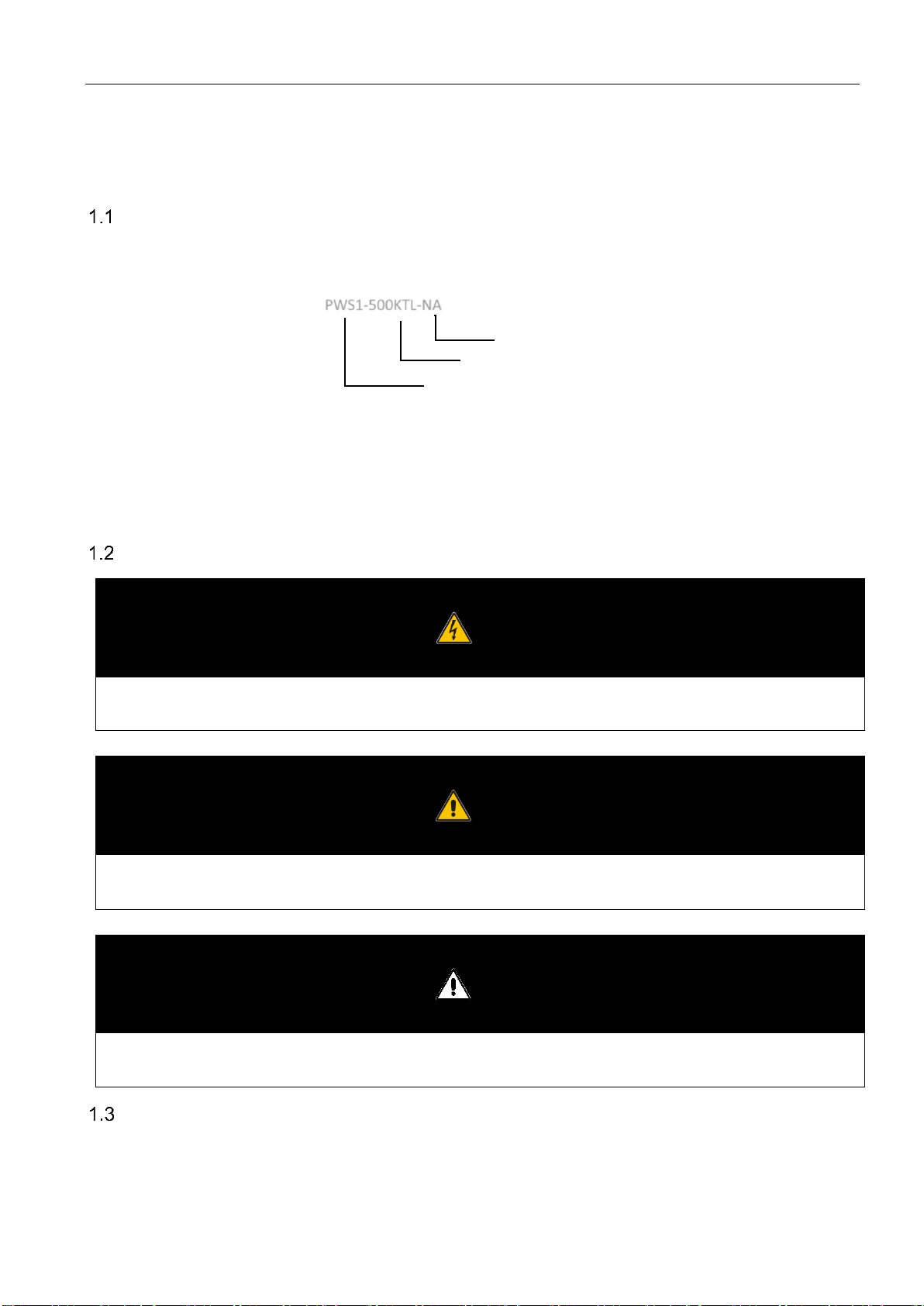
This section introduces product model definition in this user’s manual, as shown in Fig. 1-1:
Fig.1-1 Product model definition
For example
PWS1-500KTL-NA: 500KW Bi-directional storage inverter without isolation transformer
Symbolic interpretation
Danger
This instruction indicates that there is a safety risk during operation. If this kind of warning information is not followed, it will directly result
in a serious human casualty accident.
Warning
This instruction indicates that there is a potential risk during operation. If this kind of warning information is not followed, it might result in a
serious human casualty accident.
Attention
This instruction indicates that there is a potential risk during operation. If this kind of warning information is not followed, it might result in
device damage.
System application
As shown in Fig.1-2, energy storing power generation system is composed of battery, the storage inverter and AC distribution
unit. Batteries are input to the storage inverter after series-parallel connection of batteries. The storage inverter outputs it to
PWS1-500KTL-NA
Bi-directional Storage Inverter
Rated Power: 500K
NA: For North America

2 Chapter I Overview
AC distribution unit. It operates in different modes according to the need.
The storage inverter plays a core role in the whole system and is characterized with high conversion efficiency, wide range
input voltage, rapid on/off-grid switching and convenient maintenance. It has a complete protection function (such as islanding
protection, DC overvoltage protection, AC overvoltage-under-voltage protection, over-frequency/under-frequency protection,
inverted sequence protection and output overload protection) and can meet on/off-grid operation requirements. The input side
of the storage inverter can be 1-Sting Configuration, 4-Sting Configuration and 8-Sting Configuration.
Battery
bank PCS Grid
AC
distribution
box
Fig.1-2 Energy storing system diagram
Attention
PWS1-500KTL- NA storage inverter is without an isolation transformer.
An External Transformer IS required to be deployed between the inverter and the Utility
Power Grid.
The External Transformer shall be compliant to the following conditions:
Comply with ANSI C57.12.50-1981(R1998) or ANSI/UL1561
Capacity shall be 500KVA
The primary voltage and secondary voltage shall be - Grid Voltage (480V in US, et al ):400V
Be Isolated transformer
Safety instructions
This user’s manual is about installation and use of Sinexcel PWS1-500KTL-NA storage inverter without transformer.
Before installation, please read this user’s manual carefully.
The storage inverter must be commissioned and maintained by the engineers designated by the manufacturer or the
authorized service partner. Otherwise, it might endanger personal safety and result in device fault. Any damage against the
device caused thereby shall not be within the warranty scope.
The storage inverter is only used for commercial/industrial purposes, and it cannot be used as an energy saving device related
to life support device.
Danger

Chapter I Overview 3
Any contact with copper bar, contactor and terminal inside the device or connected with the loop of power grid might result in burning or
fatal electric shock.
Don’t touch any terminal and conductor connected with the loop of power grid.
Pay attention to any instruction and safety documents about power on-grid.
Warning
There might be an electric shock risk inside the device!
Any operation related to this device will be conducted by professionals.
Pay attention to the safety precautions listed in safety instruction and installation documents.
Pay attention to the safety precautions listed in user’s manual and other documents.
Warning—large leakage current
Before connecting input power supply, please ensure that the grounding is reliable.
The device grounding must comply with the local electric codes.
Warning
When storage battery is connected to storage inverter, there is DC voltage at input port. Please pay attention to it during operation.
Warning
Don’t touch electric parts within 15 minutes after power outage!
There is dangerous energy in capacitance storage. Don’t touch device terminal, contactor and cooper bar and other electric parts
within 15 minutes after disconnecting all device power supplies.
Attention
All maintenance and preservation inside the device require using tools and shall be conducted by trained personnel. The
components behind the protective cover plate which are opened by tools cannot be maintained by users.
Please read this user’s manual before operation.

4 Chapter I Overview
Precautions
1.5.1 Personnel requirements
The storage inverter is only commissioned and maintained by the engineers designated by the manufacturer or the authorized
service partner. Otherwise, it might endanger personal safety and result in device fault. Any damage against the device caused
thereby shall not be within the warranty scope.
1.5.2 Equipment use scope
The storage inverter is only used for commercial/industrial purposes, and it cannot be used as an energy saving device related
to life support device.
1.5.3 Cabinet label
Cabinet label contains important information for safe operation of cabinet. Don’t tear it up or damage it. S
Ensure that the cabinet label is clear and readable. If it is damaged or obscure, please replace it immediately.
1.5.4 Description
To facilitate users to use this manual more conveniently, a lot of pictures have been provided in the manual. The pictures can
be only used for explanative and schematic purposes. As for product details, the real product shall prevail.
Chapter IV Device Installation 5
Chapter II Introduction to Modules
Overall dimension of PCS-AC module
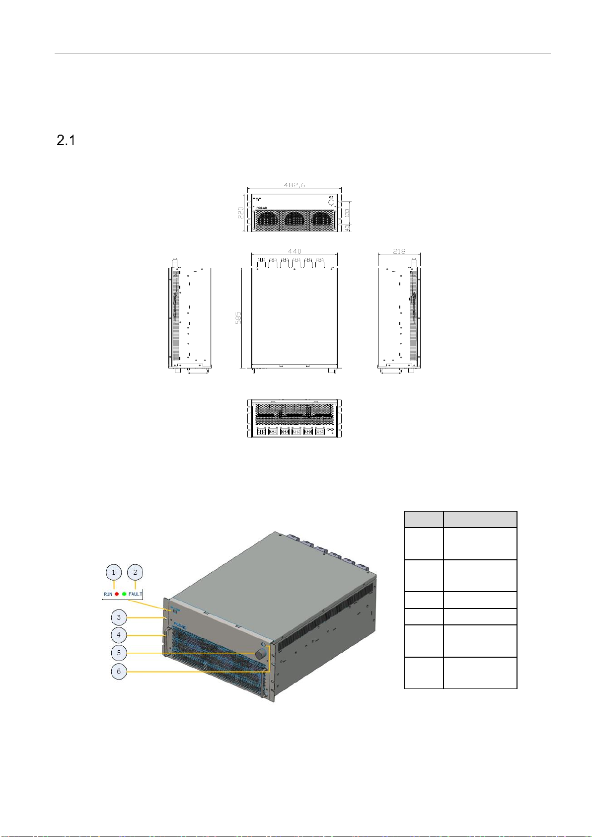
Fig.2-1 is a diagram for overall dimension of PCS-AC module case and installation hole.
Fig.2-1 Overall dimension and installation diagram for PCS-AC module
Fig. 2-2 is 3D view for front panel of PCS-AC module.
Position
Description
1
Normal indicator
light
2
Fault indicator
light
3
Hanger
4
Handle
5
Communication
cable
6
Power supply
cable
Fig. 2-2 Front 3D view for PCS-AC module

6Chapter IV Device Installation
Warning
The handle on the front panel of the module cannot bear the load.
The front panel of PCS-AC module has two LED lights, namely one green (Normal) light and one red (Alarm) light. When the
device is in standby state, the green light (Normal) flickers once every 1s. When the device is in sleep state, green and red
lights are off. When the device is in normal operation, the green light (Normal) is always on. When the device has a fault
warning, the red light (Alarm) will be always on or flicker.
Chapter IV Device Installation 7
Chapter III Introduction to System
System composition
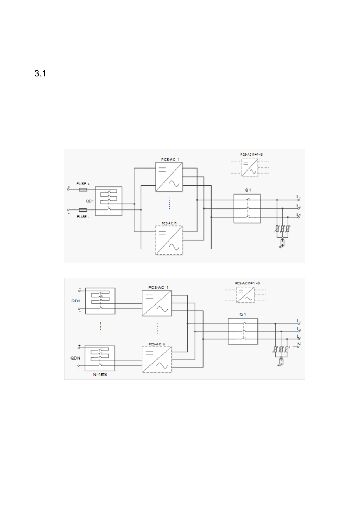
PWS1-500KTL-NA storage inverter is composed of 8 PCS-AC modules. The modules identify master-slave systems through
the dial-up codes on the panel. #1 is a master system, while other modules track the master system. The storage inverter
cabinet is equipped with lightning protector, AC/DC breaker. Fig.3-1 and 3-2 is a topological graph for its composition and
structure.
Fig.3-1 Topological graph for storage inverter with 1-Sting Configuration
Fig.3-2 Topological graph for storage inverter with 4/8-Sting Configuration
Main composition of PWS1-500KTL-NA. The storage inverter cabinet is shown in Table.3-1.
8Chapter IV Device Installation
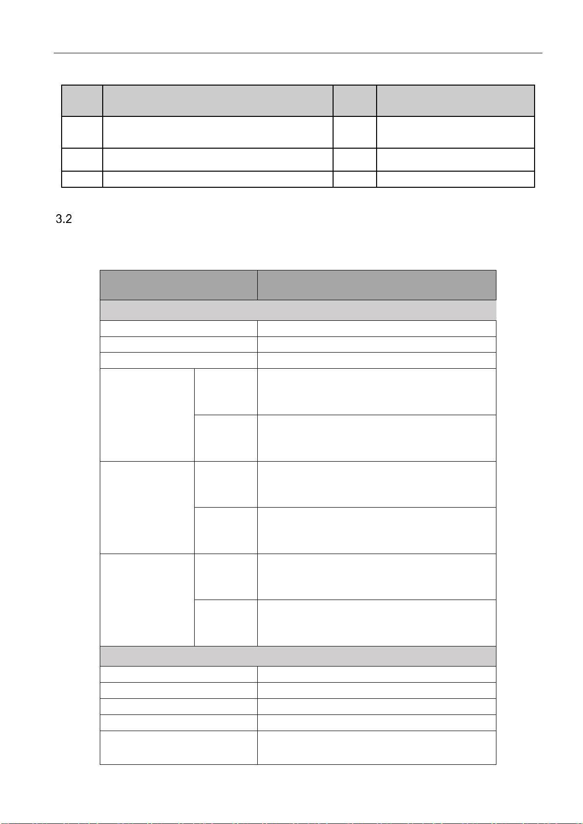
Table 3-1 Main composition of the storage inverter cabinet
Serial
No.
Name
Quantity
Remark
1
Cabinet
1 plane
The cabinet is equipped with distribution
components.
2
PCS-AC module
8 set(s)
3
Power Management Unit
1 set
It is installed in the cabinet door.
Technical parameters
Table 3-2 is detailed parameters for storage inverter.
Table 3-2 Technical parameters
Product Model
PWS1-500KTL-NA
DC Input - BATTERY
Battery Voltage Range
630V~900V
DC Max Current(Total)
873A
Quantity of Battery Strings
1/4/8
1-String
Configuration
Max
Current
per String
873A
Max
Power per
String
550kW
4-String
Configuration
Max
Current
per String
218A
Max
Power per
String
137.5kW
8-String
Configuration
Max
Current
per String
109A
Max
Power per
String
68.75kW
AC Grid-interactive mode
Rated Output Power
500kW
AC Max Power
550kVA
Rated Voltage
400V
Voltage Range
±15%
Rated Frequency
60Hz(59.5Hz~60.5Hz)

Chapter IV Device Installation 9
AC Rated Current
760A
AC Max Current
836A
Output THDi
≤3%
Power Factor
0~0.8 leading or lagging
AC Stand-alone mode
Voltage
400V
Voltage adjustable range
±10%
Frequency
60Hz(59.5Hz~60.5Hz)
Output THDu
≤2%(Linear load)
System
CEC Efficiency
97%
Wiring Mode
3-Phase 3-Wire
Isolation Mode
Non-isolation
Cooling
Forced air cooling
Noise
70dB
Ambient Temperature.
-20℃~50℃
Protection
IP20 / NEMA1
Max Elevation
3000m
Humidity Range
0~95% (No condensation)
Size (W*H*D)
1100mm*2160mm*800mm
Weight
600kg
COMMUNICATION
Display
Touch Screen
Communication Protocol
Modbus TCP/IP, Modbus RTU
Communication Socket
Ethernet, RS485, CAN
Grid-Support Functions
H/LVRT
Yes
H/LFRT
Yes
Ramp Rate
Yes
Fixed PF
Yes
Volt-Watt
Yes
Volt-Var
Yes
Freq-Watt
Yes
Grid-Support Function Accuracy
Voltage
1%
Current
1%
(Volt-Watt)Active Power
10%
(Volt-Var)Reactive Power
6%
Frequency
0.02Hz
PF
0.01
10 Chapter IV Device Installation
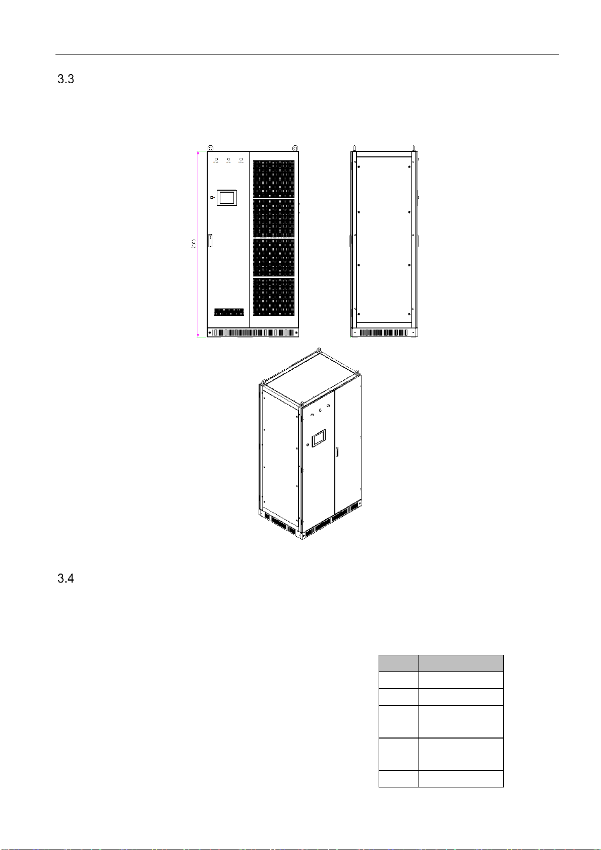
Dimension
The dimension of the storage inverter is shown in Fig.3-3. Cabinet width: 1100mm, height: 2,160mm (without ring); depth:
800mm.
Fig. 3-3 Overall dimension of storage inverter
Appearance description
The appearance of the storage inverter is shown in Fig.3-4. Screen body is mainly composed of touch screen, normal indicator
light, alarm indicator light and emergency shutdown button etc.
Position
Description
1
Power indicator light
2
Fault indicator light
3
Normal indicator
light
4
Emergency
shutdown button
5
Touch screen

Chapter IV Device Installation 11
Fig. 3-4 Appearance diagram for PWS1-500KTL-NA storage inverter
12 Chapter IV Device Installation
Chapter IV Device Installation
Transport and storage
Cabinet and module of the storage inverter are packed together in the packing cases. During device transport and storage,
pay attention to the logo on the packing case.
The storage inverter is modularly designed so as to facilitate device positioning and transport. The selection of storing position
should ensure that:
There is no corrosive gas around it.
There are over-wetting and high-temperature sources.
It is not a dusty environment.
It complies with the firefighting requirements.
Attention
During cabinet transport and storage, stacking is not allowed. The device top cannot be placed with other articles.
The cabinet should be placed vertically at forward direction. Don’t keep it upright place it horizontally.
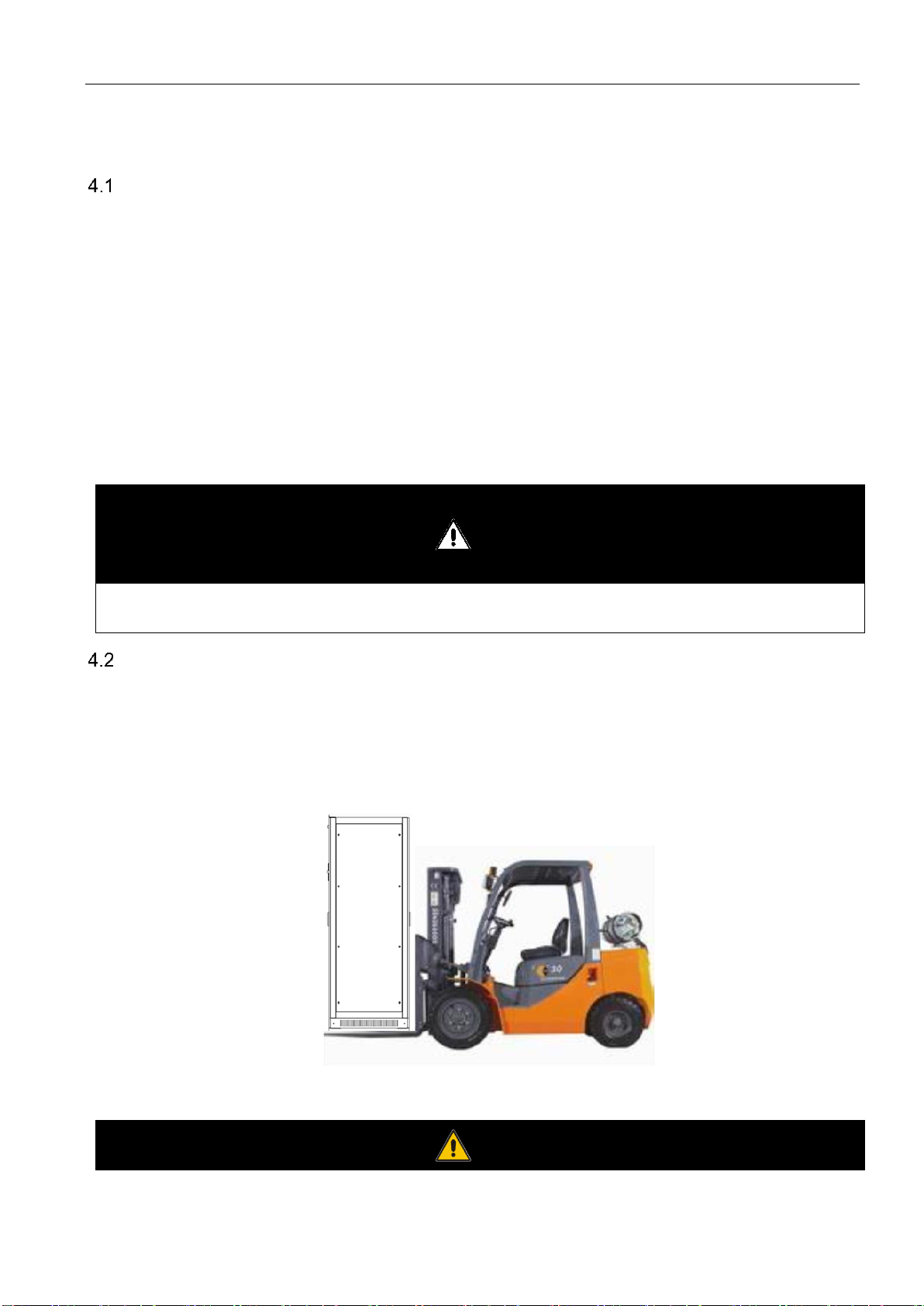
Removal
When removing the module of the storage inverter which is not unpacked from packing case, a forklift can be used to remove
the whole case.
Users can lift the device bottom with a forklift or remove the cabinet of single the storage inverter through the lifting hole on its
top with a crane. It can be transported alone. Refer to Fig. 4-1.
Fig.4-1 Moving method for storage inverter
Warning
Table of contents
Other Sinexcel Inverter manuals


Popular Inverter manuals by other brands


Suntrica
Suntrica SolarBadge user guide

Northern Lights
Northern Lights NL773LW3 Operator's manual

Xantrex
Xantrex GT100 Series Planning and installation manual

Newton Waterproofing
Newton Waterproofing Victron MultiPlus 12/3000/120 installation manual

XCSOURCE
XCSOURCE UES-2410 user manual

Hoymiles
Hoymiles HM-400NT Quick installation guide