manuals.online logo
Brands
  1. Home
  2. •
  3. Brands
  4. •
  5. Singer Valve
  6. •
  7. Control Unit
  8. •
  9. Singer Valve 206-DW Assembly instructions

Singer Valve 206-DW Assembly instructions

12850-87
th
Avenue
Surrey, BC. Canada. V3W 3H9
Ph: 604-594-5404
Fx: 604-594-8845
www.singervalve.com
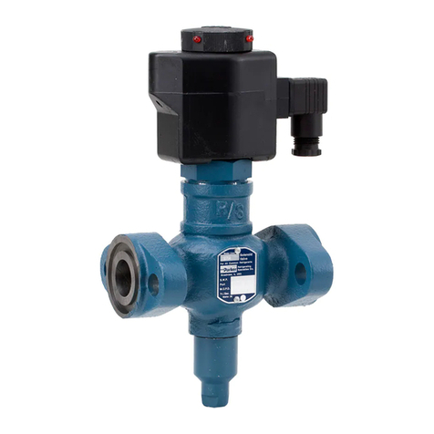
SINGER MODEL 106/206-DW
Double Chamber, Bypass Pump Control Valve
Deep Well Pump Control Valve
Installation, Operating and Maintenance Instructions
Schematic A-7514C
DESCRIPTION:
Singer Model 106/206-DW is a deep well pump
control valve designed to eliminate starting and
stopping surges of deep well pumps.
The main valve is a single seated, hydraulically
operated, diaphragm actuated, globe or angle pattern
valve. The main valve is controlled by a solenoid
pilot valve, utilizing line pressure for operation. The
valve has a Limit Switch, which shuts down the pump
when the pumping cycle is completed.
DESCRIPTION OF OPERATION:
Model 106/206-DW is installed in a tee between the
pump discharge and the check valve. The pump is
started and stopped on an open valve. The discharge
may be returned to the well or to an open drain.
The valve is wide open when the pump is off. When
the pump is started, the valve discharges initial rush
of sand and water from the pump column to waste.
Solenoid Valve (7) is energized and the Main Valve
starts closing. The closing speed is adjustable. Main
Valve (1) closes slowly; flow into system increases
gradually, preventing starting surges.
On shutdown Solenoid Valve (7) is de-energized.
Main Valve (1) opens slowly. Opening speed is
adjustable. While the Main Valve is opening, Limit
Switch (9) keeps the pump running. As the Main
Valve opens, flow into the system decreases
gradually. Pump stopping surges are prevented.
When the Main Valve is almost fully open, Limit
Switch (9) stops the pump.
INSTALLATION:
1. See 106/206-PT "Installation".
2. Connect the operating pressure connection (5) to
the header, downstream of the pump check
valve. (See schematic).
NOTE REGARDING SIZE AND CAPACITY OF
THIS CONNECTION:
Use 3/8" copper tube up to 10 ft of distance, 1/2"
copper tube for longer runs. All fittings and drilled
holes must be full nominal size for reliable
operation.
3. Connect Solenoid Valve (7) and Limit Switch (9)
to the electrical system. Check Solenoid Valve
name plate for correct pressure. Check side of
coil for correct voltage. Connections in the Limit
Switch must be to common and normally closed
terminals. See 'Suggested Wiring Diagram'.
4. If the outlet pipe has a submerged discharge or
any other reason to develop sub-atmospheric
pressure, a vacuum breaker is recommended to
reduce cavitation damage.
ADJUSTING PROCEDURE:
1. Close Opening Speed Control (8) and Closing
Speed Control (2).
2. Start the pump.
3. Open Closing Speed Control (2) slowly until
desired closing speed is achieved.
4. Turn the pump switch to off position. The pump
should continue to run.
5. Open Opening Speed Control (8) slowly until
desired opening speed is achieved.
6. When the valve is almost fully open, Limit Switch
(9) should stop the pump. If the pump does not
stop, adjust the Limit Switch.
7. Excessively long opening and closing times
should be avoided because this may affect the
pump motor and may also cause plugging of the
speed controls by any solids in the water.
IOM A-7514C Page 1 of 2 August 2004
12850-87
th
Avenue
Surrey, BC. Canada. V3W 3H9
Ph: 604-594-5404
Fx: 604-594-8845
www.singervalve.com
Adjusting Procedure (Cont.):
FINAL ADJUSTMENT OF LIMIT SWITCH:
Limit Switch (9) should be adjusted to shut the pump
off as soon as the main line check valve closes.
The point at which the main line check valve closes
can be determined by observing pressure gauges on
the inlet and outlet sides of the check valve. The
check valve is closed when the inlet pressure is lower
than the outlet pressure. If pressure gauges have not
been installed, it may be possible to determine when
the check valve closes by listening for the check inner
valve contacting the seat.
SERVICE SUGGESTIONS:
Fails to close:
1. Lack of pressure in the bonnet due to:
•Lack of pressure in the Connection to Header
(5). / Isolate the valve to fill the system.
(Original start-up to fill the system)
•Connection to header done improperly. /
Assure that header pressure reaches Solenoid
Valve (7).
2. Closing Speed Control (2) closed tight. / Open 1/2
turn or as required.
3. Solenoid Valve (7) not energized or not operating
properly / Check wiring and refer to solenoid valve
instructions.
4. Main Valve diaphragm ruptured or main valve
obstructed. / Refer to 106-PT instructions.
Fails to open
1. Opening Speed Control (8) closed tight. / Open
1/2 turn or as required.
2. Solenoid Valve (7) incorrectly wired. / Refer to
wiring diagram.
3. Pilot system obstructed between bonnet of Main
Valve (1) and atmosphere. / Locate the
obstruction and remove.
Pump re-starts after stopping.
- Incorrect wiring.
Pump runs too far on its curve on shut-down.
- See
FINAL ADJUSTMENT OF LIMIT SWITCH
above.
Pump runs too far on its curve on start-up.
- Consider installing a properly sized orifice
plate on valve inlet.
Difficulty controlling closing and/or opening
speed.
- Consider using fixed restrictions in place of
speed controls.
IOM A-7514C Page 2 of 2 August 2004
This manual suits for next models

1

Other Singer Valve Control Unit manuals

Singer Valve 106-PR-48 Assembly instructions

Singer Valve

Singer Valve 106-PR-48 Assembly instructions

Singer Valve 106-EF-8837BX Assembly instructions

Singer Valve

Singer Valve 106-EF-8837BX Assembly instructions

Singer Valve 106-PG User manual

Singer Valve

Singer Valve 106-PG User manual

Singer Valve 106-RPS-D Assembly instructions

Singer Valve

Singer Valve 106-RPS-D Assembly instructions

Singer Valve 206-RPS Assembly instructions

Singer Valve

Singer Valve 206-RPS Assembly instructions

Singer Valve 106-RF Assembly instructions

Singer Valve

Singer Valve 106-RF Assembly instructions

Singer Valve 106-RPS-RR User manual

Singer Valve

Singer Valve 106-RPS-RR User manual

Singer Valve 106-2SC-PCO Assembly instructions

Singer Valve

Singer Valve 106-2SC-PCO Assembly instructions

Singer Valve 106-PG-BPC Assembly instructions

Singer Valve

Singer Valve 106-PG-BPC Assembly instructions

Singer Valve 160 User manual

Singer Valve

Singer Valve 160 User manual

Singer Valve 206-HC Assembly instructions

Singer Valve

Singer Valve 206-HC Assembly instructions

Singer Valve 106-SC Assembly instructions

Singer Valve

Singer Valve 106-SC Assembly instructions

Popular Control Unit manuals by other brands

Burkert 8835 operating instructions

Burkert

Burkert 8835 operating instructions

Pentair Fleck 2850 Service manual

Pentair

Pentair Fleck 2850 Service manual

metso automation VALUE-LINE 6F Series Installation maintenance and operating instructions

metso automation

metso automation VALUE-LINE 6F Series Installation maintenance and operating instructions

Burkert 1134 operating instructions

Burkert

Burkert 1134 operating instructions

Simons Voss Technologies SOM + SREL3.ADV manual

Simons Voss Technologies

Simons Voss Technologies SOM + SREL3.ADV manual

Danfoss AB-QM series installation guide

Danfoss

Danfoss AB-QM series installation guide

Nice UST1-FU Instructions and information for installation and use

Nice

Nice UST1-FU Instructions and information for installation and use

Automationdirect.com Productivity 1000 P1-16CDR manual

Automationdirect.com

Automationdirect.com Productivity 1000 P1-16CDR manual

DEWESOFT V21-1 How-to guide

DEWESOFT

DEWESOFT V21-1 How-to guide

Lenze 2131 operating instructions

Lenze

Lenze 2131 operating instructions

Chauvet Stage Designer 50 TFX-48B user manual

Chauvet

Chauvet Stage Designer 50 TFX-48B user manual

Field Controls CK-92FVP quick start guide

Field Controls

Field Controls CK-92FVP quick start guide

Samson 3244 operating instructions

Samson

Samson 3244 operating instructions

AcSiP S76S manual

AcSiP

AcSiP S76S manual

MaxStream XCite manual

MaxStream

MaxStream XCite manual

Texas Instruments ADC12DJ3200 user guide

Texas Instruments

Texas Instruments ADC12DJ3200 user guide

Hirschmann PRS 80 Operators & service manual

Hirschmann

Hirschmann PRS 80 Operators & service manual

Metso Full Bore Fire-Tite 9REL Series Installation maintenance and operating instructions

Metso

Metso Full Bore Fire-Tite 9REL Series Installation maintenance and operating instructions

manuals.online logo
manuals.online logoBrands
  • About & Mission
  • Contact us
  • Privacy Policy
  • Terms and Conditions

Copyright 2025 Manuals.Online. All Rights Reserved.