Parker S7A Service manual
Other Parker Control Unit manuals

Parker
Parker HASV08R User manual
Parker
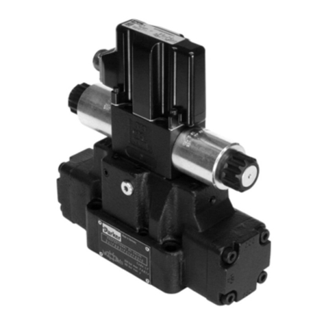
Parker H Series User manual
Parker
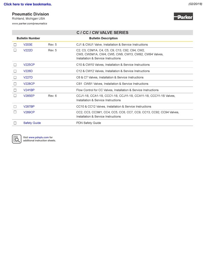
Parker DxFB Series User manual
Parker
Parker CW Series Operating instructions
Parker
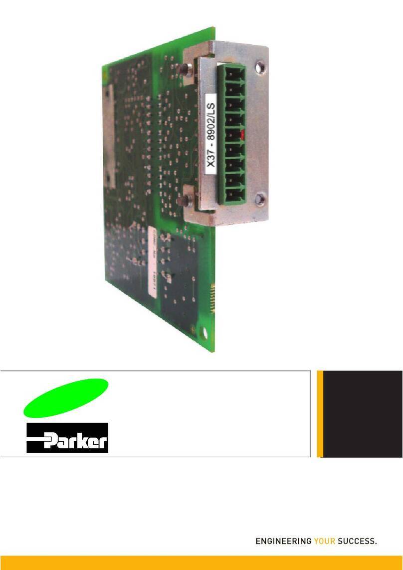
Parker 8902/LS User manual
Parker
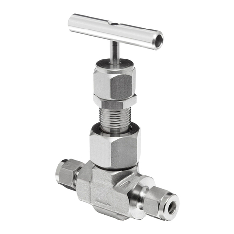
Parker U Series Technical specifications
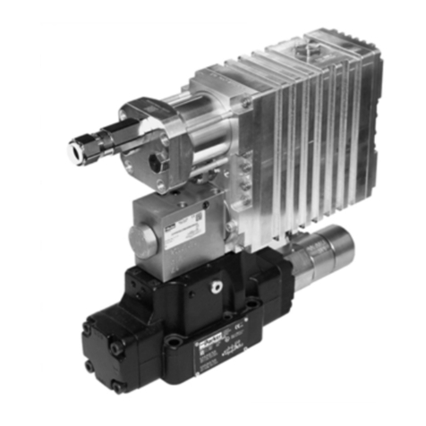
Parker
Parker D Series User manual
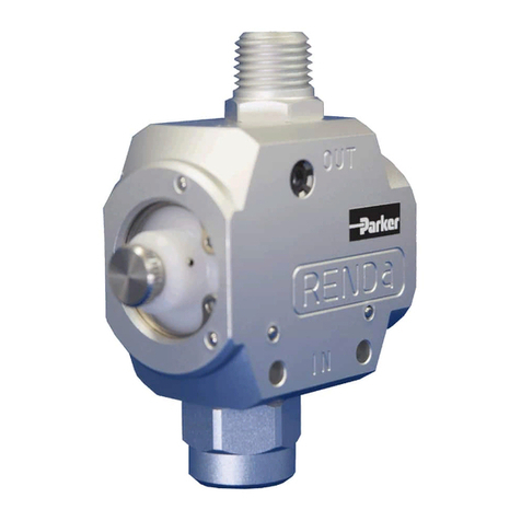
Parker
Parker HASV08R User manual
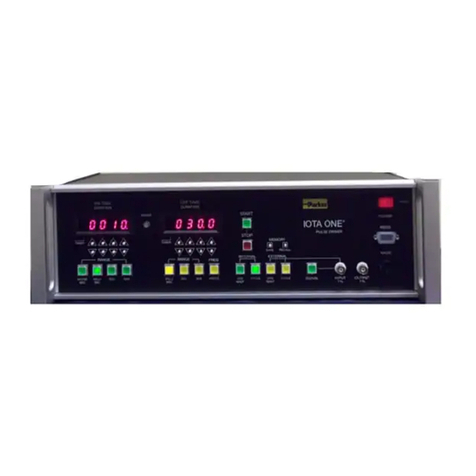
Parker
Parker IOTA ONE Series User manual
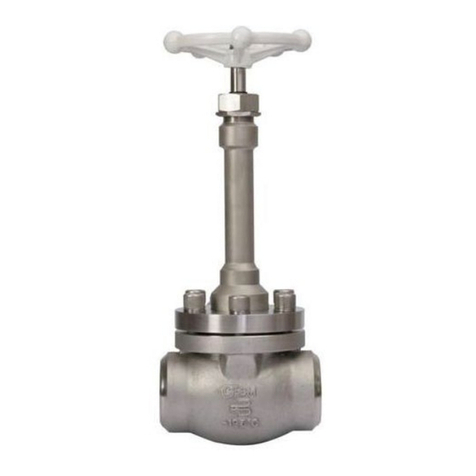
Parker
Parker DN80 User manual
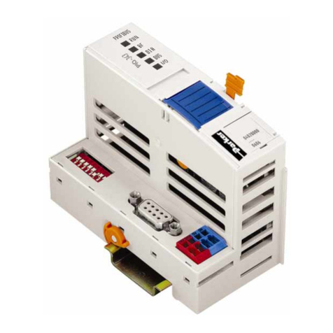
Parker
Parker PIO-400 User manual
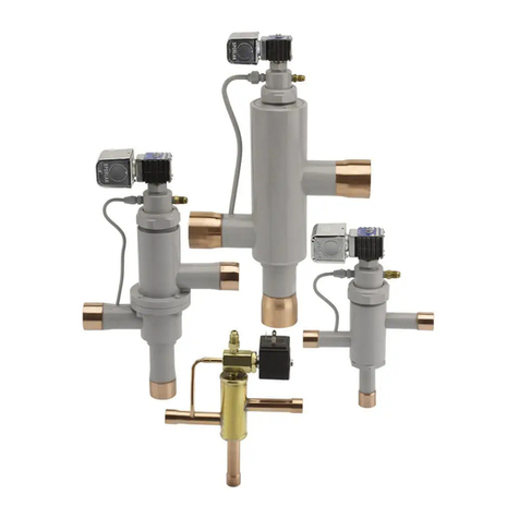
Parker
Parker Sporlan B5D Series User guide
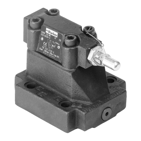
Parker
Parker R4V Series Wiring diagram
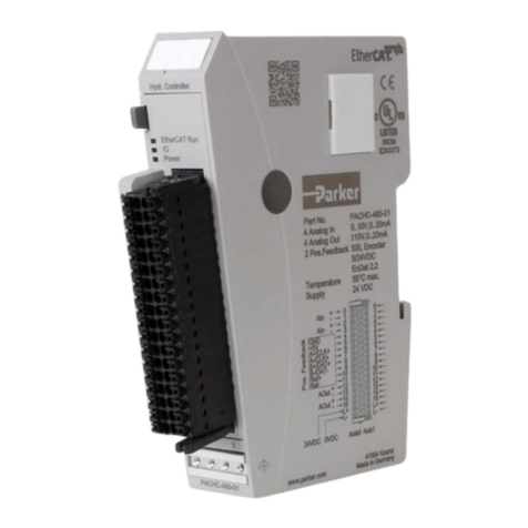
Parker
Parker PACHC Series User manual

Parker
Parker Racor 200 Series User manual
Parker
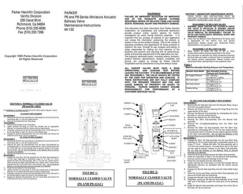
Parker P6 Technical specifications
Parker
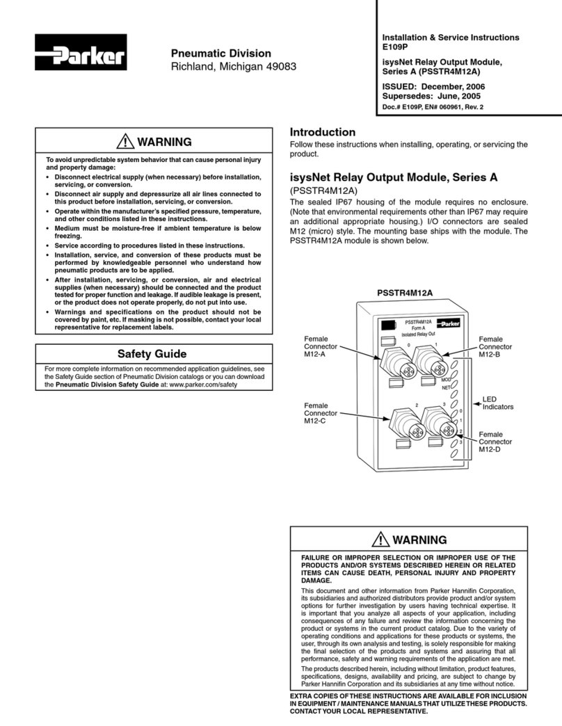
Parker PSSTR4M12A Installation and maintenance instructions

Parker
Parker PSST8M23A Installation and maintenance instructions
Parker
Parker S4AD User manual

Parker
Parker Series PCD 00A-400 User manual
Popular Control Unit manuals by other brands

Festo
Festo Compact Performance CP-FB6-E Brief description

Elo TouchSystems
Elo TouchSystems DMS-SA19P-EXTME Quick installation guide

JS Automation
JS Automation MPC3034A user manual

JAUDT
JAUDT SW GII 6406 Series Translation of the original operating instructions

Spektrum
Spektrum Air Module System manual

BOC Edwards
BOC Edwards Q Series instruction manual

KHADAS
KHADAS BT Magic quick start

Etherma
Etherma eNEXHO-IL Assembly and operating instructions

PMFoundations
PMFoundations Attenuverter Assembly guide

GEA
GEA VARIVENT Operating instruction

Walther Systemtechnik
Walther Systemtechnik VMS-05 Assembly instructions

Altronix
Altronix LINQ8PD Installation and programming manual
