manuals.online logo
Brands
  1. Home
  2. •
  3. Brands
  4. •
  5. Singer
  6. •
  7. Sewing Machine
  8. •
  9. Singer 1669U101 User manual

Singer 1669U101 User manual

This manual suits for next models

5

Other Singer Sewing Machine manuals

Singer EM9305 User manual

Singer

Singer EM9305 User manual

Singer Fashionista S800 User manual

Singer

Singer Fashionista S800 User manual

Singer 66 -  2 User manual

Singer

Singer 66 - 2 User manual

Singer 7174 User manual

Singer

Singer 7174 User manual

Singer XL-550 User manual

Singer

Singer XL-550 User manual

Singer 132B6 User manual

Singer

Singer 132B6 User manual

Singer 301 Installation and operation manual

Singer

Singer 301 Installation and operation manual

Singer 302U201 User manual

Singer

Singer 302U201 User manual

Singer 15K - MANUAL 2 User manual

Singer

Singer 15K - MANUAL 2 User manual

Singer 175-60 User manual

Singer

Singer 175-60 User manual

Singer 2662 User manual

Singer

Singer 2662 User manual

Singer 107W50 User manual

Singer

Singer 107W50 User manual

Singer Heavy Duty 14HD854 User manual

Singer

Singer Heavy Duty 14HD854 User manual

Singer Touch & Sew 604 User manual

Singer

Singer Touch & Sew 604 User manual

Singer 3400 User manual

Singer

Singer 3400 User manual

Singer 19-18 User manual

Singer

Singer 19-18 User manual

Singer 175-36 User manual

Singer

Singer 175-36 User manual

Singer 6038 Product guide

Singer

Singer 6038 Product guide

Singer 5160 User manual

Singer

Singer 5160 User manual

Singer 127-4 User manual

Singer

Singer 127-4 User manual

Singer 160 User manual

Singer

Singer 160 User manual

Singer 1234 User manual

Singer

Singer 1234 User manual

Singer 176-11 User manual

Singer

Singer 176-11 User manual

Singer 245-1 User manual

Singer

Singer 245-1 User manual

Popular Sewing Machine manuals by other brands

Brother PE-180D Service manual

Brother

Brother PE-180D Service manual

ELNA 2002 instruction manual

ELNA

ELNA 2002 instruction manual

Siruba DL7200D-NM1 Instruction book

Siruba

Siruba DL7200D-NM1 Instruction book

Silver Viscount 9500e instruction manual

Silver

Silver Viscount 9500e instruction manual

Pfaff 3588-05/020 instruction manual

Pfaff

Pfaff 3588-05/020 instruction manual

JUKI DDL-9000A instruction manual

JUKI

JUKI DDL-9000A instruction manual

Pfaff 284 Instruction book

Pfaff

Pfaff 284 Instruction book

Reliable MSK-335B Specification sheet

Reliable

Reliable MSK-335B Specification sheet

Kenmore 385. 19000 owner's manual

Kenmore

Kenmore 385. 19000 owner's manual

Brother FD4-B271 instruction manual

Brother

Brother FD4-B271 instruction manual

Brother Computerized Embroidery Machine Operation manual

Brother

Brother Computerized Embroidery Machine Operation manual

Husqvarna Viking Designer SE user guide

Husqvarna Viking

Husqvarna Viking Designer SE user guide

Riccar RL634DE user manual

Riccar

Riccar RL634DE user manual

ZOJE ZJ9800 Operation manual

ZOJE

ZOJE ZJ9800 Operation manual

Siruba C007JP Instruction book

Siruba

Siruba C007JP Instruction book

IKEA SY user guide

IKEA

IKEA SY user guide

Pfaff 571 instruction manual

Pfaff

Pfaff 571 instruction manual

Brother BB370 Quick setup guide

Brother

Brother BB370 Quick setup guide

manuals.online logo
manuals.online logoBrands
  • About & Mission
  • Contact us
  • Privacy Policy
  • Terms and Conditions

Copyright 2025 Manuals.Online. All Rights Reserved.

Service Manual
SINGER®
MACHINE
1669U
101
102
200
300
400
500
@A
registered
trademark
of
The Singer
Company
L1m1ted
Copyr:ght@l
998
The Singer
Company
Limited
All Rights Reserved Throughout The
World
From the library of Superior Sewing Machine & Supply LLC - www.supsew.com
CONTENTS
1. PREFACE ..................................
...
....................................
...
..
..
...
..
...
..
.....
...
..
..
.....
..
.....
...
. 1
2. NOTES ON SAFETY .
...
...
..
.......
..
.........
...
..
..
..
..
....
..
.
.. .. ..
.
..
...
..
..
..
......
..
..
..
......
..
..
...
..
......
..
..
. 1
3.
MEANINGS
OF
THE SYMBOLS ................................................................................. 1
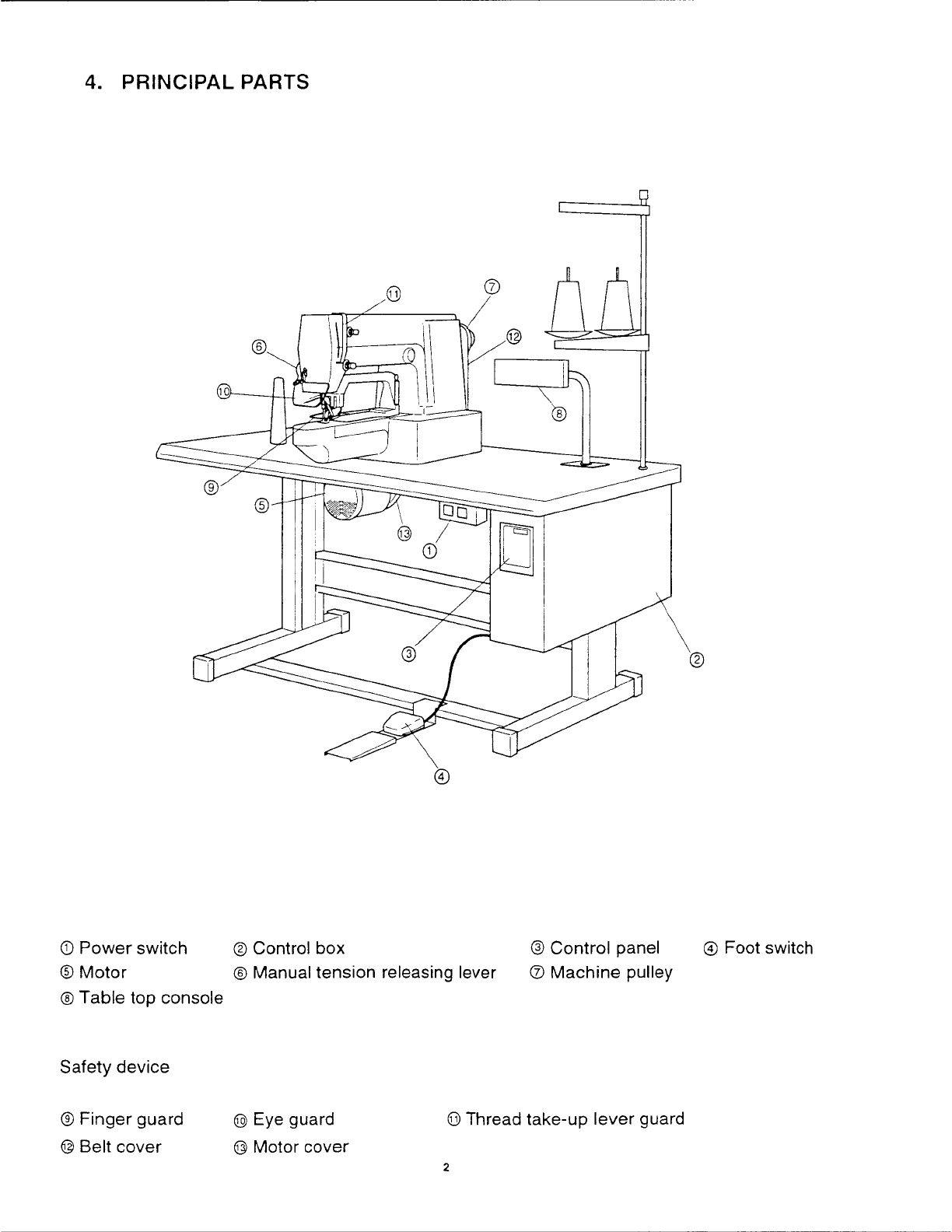
4. PRINCIPAL PARTS ..................................................................................................... 2
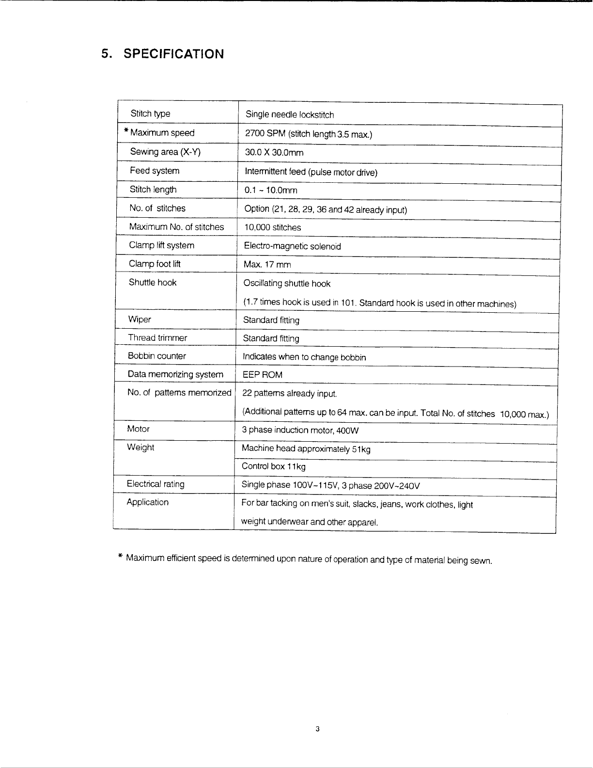
5. SPECIFICATION ........................................................................................................... 3
6. ADJUSTMENT OF NEEDLE AND SHUTTLE ............................................................... 4
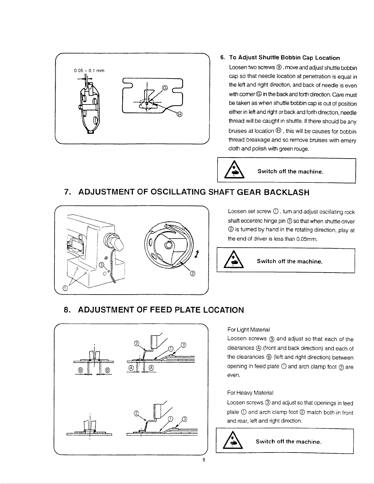
7. ADJUSTMENT OF OSCILLATING SHAFT GEAR BACKLASH ................................... 5
8. ADJUSTMENT OF FEED PLATE LOCATION .............................................................. 5
9.
TO
ADJUST POSITION OF PRESSER FOOT .............................................................. 6
10. TO ADJUST POSITION OF CAM BRACKET ............................................................... 7
11.
ADJUSTMENT OF WIPER HEIGHT ............................................................................. 8
12.
TO
ADJUST TENSION RELEASING BAR SOLENOID ................................................ 8
13.
TO
ADJUST POSITION OF THREAD TRIMMER CAM ................................................ 9
14.
TO
ADJUST HEIGHT OF ROLLER .............................................................................. 1
O
15. TO ADJUST POSITION OF
SHAFT
.............................................................................. 10
16. TO ADJUST LENGTH OF KNIFE BAR OPERATING LEVER CONNECTING ROD .....
11
17. ADJUSTMENT OF KNIFE POSITION ..........................................................................
11
18.
TO
TIME THREAD TRIMMER .....................................................................................
12
19. ADJUSTMENT OF CLAMP FOOT HEIGHT ..................................................................
12
20.
TO
ADJUST SENSOR ...................................................................................................
12
21.
TO
INSTALL SYNCHRONIZER ....................................................................................
13
22.
TO
ADJUST SYNCHRONIZER .....................................................................................13
23. ADJUSTMENT OF BUTTONHOLE SEWING MACHINE (1669U 200) .........................
14
24. ADJUSTMENT
OF
BUTTON SEWING MACHINE (1669U 400) ...................................
16
25. CHECK
MODE
............................................................................................................
21
26. TABLE TOP CONSOLE
CHECK
MODE (OPTION) .....................................................
25
27. ERROR
CODE
NUMBERS............................................................................................
29
28. GREASING POINTS .....................................................................................................30
29. TROUBLE-SHOOTING GUIDE .....................................................................................
31
30. CONTROL BOX DIAGRAM ..........................................................................................
36
31. MAIN
CONTROL
BOARD DIAGRAM ............................................................................
37
32.
D.
C
POWER
SUPPLY BOARD DIAGRAM .................................................................
38
33. INVERTER BOARD DIAGRAM .....................................................................................
38
From the library of Superior Sewing Machine & Supply LLC - www.supsew.com
1. PREFACE
This service manual
is
to
explain the methods to be used
for
adjusting various parts ofthe
machine
and
intended for use by mechanics and service personnel.
When adjusting the machine, it is recommended that you
make
reference not only to this
"Service
Manual"
but also to the "Operator's Guide" and "Parts List" furnished with the
machine.
2. NOTES ON SAFETY
• When exchanging gauge parts (e.g. needle, presser foot, needle plate, feed plate, bob-
bin)
or
when
changing setting condition of the
machine,
during threading, when the
machine
is left unattended or during service work, be
sure
to turn main switch off or
disconnect
the
main plug.
In
case it is
necessary
to
check
the machine
or
perform
service
work
with the main switch on, care should be taken not to press the foot start
inadvertently.
• General service work must be carried out only
by
appropriately trained persons.
• Repair, conversion and special maintenance work must be carried out only by techni-
cians or persons with appropriate training.
• When safety devices have been removed, be sure to replace them and make sure they
perform properly after completion of adjustment
or
service work.
• Work
on
electrical equipment must be carried out by electricians or appropriately trained
persons.
•
When
exchanging parts, be sure to use Singer approved parts.
• When exchanging gauge parts (e.g. needle, presser foot, needle plate, feed plate, bob-
bin), be sure to use correct parts.
• Singer shall not be liable for any damages caused by modifications made on the part of
the user.
• Work on parts and systems under electric current is not permitted, except as specified
in
regulations EN50110.
• Commissioning of the sewing head
is
prohibited until such time as the entire sewing unit
is
found to comply with EC regulations.
3. MEANINGS OF THE SYMBOLS
Danger spot!
Items requiring special attention
Danger of injury to operative
or
service staff.
Be sure
to
observe and adhere to these safety notes
Earth
From the library of Superior Sewing Machine & Supply LLC - www.supsew.com
4. PRINCIPAL PARTS
CD
Power
switch
®
Control box @ Control panel
©
Foot switch
®
Motor
®Tabletop
console ® Manual tension releasing lever 0
Machine
pulley
Safety device
®
Finger guard
@ Belt cover
@ Eye guard
@ Motor cover
(jJ)
Thread take-up
lever
guard
2
From the library of Superior Sewing Machine & Supply LLC - www.supsew.com
5. SPECIFICATION
Stitch type Single needle lockstitch
*
Maximum
speed 2700 SPM (strrch length3.5 max.)
Sewing area
(X-Y)
30.0 X 30.0mm
Feed system Intermittent feed (pulse motor drive)
Stitch length
0.1
-10.0mm
No. of stitches Option (21, 28, 29, 36 and 42 already input)
Maximum
No. of stitches 10,000 stitches
Clamp lift system Electro-magnetic solenoid
Clamp foot lift
Max.17mm
Shuttle hook Oscillating shuttle hook
(1.7 times hook is used
in
101. Standard hook is
used
in other machines)
Wiper Standard fitting
Thread trimmer Standard fitting
Bobbin counter Indicates when to change bobbin
Data memorizing system
EEPROM
No. of patterns memorized 22 patterns already input.
(Additional patterns up
to
64 max. can be input. Total No. of stitches 10,000 max.)
Motor
3 phase induction motor, 400W
Weight Machine head approximately
51
kg
Control box
11
kg
Electrical rating Single phase 100V-115V, 3 phase
200V-240V
Application For bar tacking on men's suit, slacks, jeans,
work
clothes, light
weight underwearand other apparel.
*
Maximum efficient speed is determined upon nature of operation and type of material being sewn.
3
From the library of Superior Sewing Machine & Supply LLC - www.supsew.com
6.
ADJUSTMENT OF NEEDLE AND SHUTTLE
J '
I------,
5
®
4
1.
To
Adjust Needle Bar Height
Turn driving wheel by hand until needle
bar
is
at
its
lowest point. Loosen needle bar connecting link screw
@ and move needle bar
up
or down until the highest
mark®
on needle bar aligns with lowerend of needle
barlower bushing
CD·
If
Catalog No. 3355-01 needle
is
used, align
mark©
on needle bar with lower end
of
needle bar lower bushing.
2.
To Adjust Timing of Needle and Shuttle
Raise needle bar from
its
lowest point by turning driving
wheel with
hand
and align the second mark
®
on
needle bar with end of needle
bar
lower bushing
CD
.
Loosen screw 0 and
tum
shuttle body
in
the arrow
direction so that the centerof needle aligns with shuttle
point
If
Catalog No. 3355-01 needle
is
used, align mark
@ on needle
bar
with lower end of needle bar lower
bushing.
3. To Adjust Needle and Shuttle Driver
Tum
driving wheel by hand and align shuttle point
with
the
center
of
needle.
Loosen
screw
©
and turn
oscillating shaft bushing adjusting stud
®
so
thatneedle
contacts with shuttle driver.
If
shuttle driver does not
properly contact needle, needle and shuttle point will
interfere causing damage to the parts.
If
the contact
is
too heavy,
it
will cause skip stitching.
4.
Adjustment
of
Shuttle
Body
and
Driver
Rotational Direction Clearance
Tap
part®
and
®,
and adjust so that clearance
between
shuttle body and
driver
in
the
rotational
direction
is
0.3 -0.5mm.
5.
To
Adjust
Clearance
Between
Needle
and
Shuttle Point
Tum
driving wheel by hand and align shuttle point
with
the center of needle. Loosen set screw
®
and turn
shuttle race
body
adjusting stud
0
so that clearance
between needle and shuttle point
is
0.05 -
0.1
mm.
Switch off the machine.
From the library of Superior Sewing Machine & Supply LLC - www.supsew.com
6.
To
Adjust
Shuttle Bobbin Cap Location
Loosen two
screws®,
move and adjust shuttle bobbin
cap so that needle location at penetration is equal
in
the left and right direction, and back of needle
is
even
with
comer®
in
the backand forth direction. Care must
be taken as when shuttle bobbin cap
is
outof position
either
in
left and right orback and forth direction, needle
thread will be caught
in
shuttle.
If
there should be any
bruises at location ® ,this will be causes for bobbin
thread
breakage
and so remove bruises with emery
cloth and polish with green rouge.
Switch off the machine.
7. ADJUSTMENT OF OSCILLATING SHAFT
GEAR
BACKLASH
Loosen set screw
CD
,tum and adjust oscillating rock
shaft eccentric hinge pin ®so that when shuttle driver
®
is
turned
by
hand
in
the rotating direction, play at
the end of driver
is
less than 0.05mm.
Switch off the machine.
8. ADJUSTMENT OF FEED PLATE LOCATION
'
,,,,,;,
....
5
For Light Material
Loosen
screws
@ and adjust so
that
each of the
clearances ® (front and back direction) and each of
the clearances @ (left and right direction) between
opening
in
feed plate
CD
and arch clamp foot @ are
even.
For Heavy Material
Loosen screws @ and adjust so that openings
in
feed
plate
CD
and arch clamp foot @ match both
in
front
and rear, left and right direction.
Switch off the machine.
From the library of Superior Sewing Machine & Supply LLC - www.supsew.com
9.
TO
ADJUST POSITION OF PRESSER FOOT
'
'
Sideways
Y-axis
0
-~ft87l-t--t-l
++'~+-'.I
I-He»-'-
Turn machine pulley
to
bring down the needle into
needle
hole
and
position
the
presser foot
so
that
the
clearance
between
the
presser
foot
and
needle
is
equal
front
to
back
and
sideways.
Under
this
condrtion,
loosen
sensor
screw
@
and
tum
original position
reflector
CD
until
the
notch
on
the
original
position reflector
CD
is
at
the center
of
sensor@. (Both
X-axis
sensor
and
Y-
axis
sensor)
Switch off the machine.
0
__;1--1-l
-----•
-f-~p.t,,j"f~'\'b:tt---6}
6
From the library of Superior Sewing Machine & Supply LLC - www.supsew.com
10.
TO
ADJUST POSITION OF CAM BRACKET
1.
Lateral Driving Cam Bracket
Loosen
lateral
driving
cam
bracket
screw
CD
(2
places}
and
push
bracket
in
the
direction
shown
with
arrow
mark (
..
}
parallel
to
the
locating
surface
(machined
suriace).
Then
tighten
screw
(D
making
sure
that
there
is
no
play
between
lateral
driving
cam
®
and
roller
@ .
2.
Longitudinal Driving Cam Bracket
Loosen
longitudinal
driving
cam
bracket
screw©
(2
places)
and
push
bracket
in
the
direction
shown
with
arrow
mark(
..
)
parallel
to
the
locating suriace (machined suriace).
Then
tighten
screw©
making
sure
that there
is
no
play
between
longitudinal
driving
cam
®
and
roller
®·
0
©
Switch off the machine.
Longitudinal Driving Cam Bracket
7
Locating surface
\
(D
Lateral Driving Cam Bracket
------~----
-.----
~--,--------
'
'
'
From the library of Superior Sewing Machine & Supply LLC - www.supsew.com
11.
ADJUSTMENT OF WIPER HEIGHT
(101,102)
3mm-+j
__
_
25
mm
(200,
300,
500)
CD
20
mm
Loosen
screw
G)
and move wiper
bracket®
up
or
down, as required, so that clearance between wiper
and needle
point
is
3.0mm
when
wiper
passes the
needle point. Tighten screw.
Loosen screw @ and move
wiper©
to the left or
right,
as required. so that the distance between wiper point
and needle point
is
25mm. Tighten screw @ .
Switch off the machine.
Loosen screw
CD
and move bracket
@
up
ordown, as
required so that the clearance between portion
A
of
finger guard
@
and the needle point
is
3
mm
when
portion
A
of finger guard passes the needle point.
Then, loosen
screw
©
and move finger guard ® to
the left
or
right,
as
required,
so
thatthe distance between
portion
A
and the needle point is
20
mm when the
clamp
is
in
down position.
12.
TO
ADJUST
TENSION RELEASING BAR SOLENOID
8
Loosen set
screw
@
and adjust opening plate
Cg)
so
that tension
disc
©
is opened approximately
1
mm
when tension releasing bar solenoid
CD
is moved to
the end of its stroke
in
the direction shown with arrow
mark.
Note: Check to seethat tension disc
©
is
not relaxed
when tension releasing barsolenoid
(D
returns
to
its
original position bymeans of return spring.
Switch off the machine.