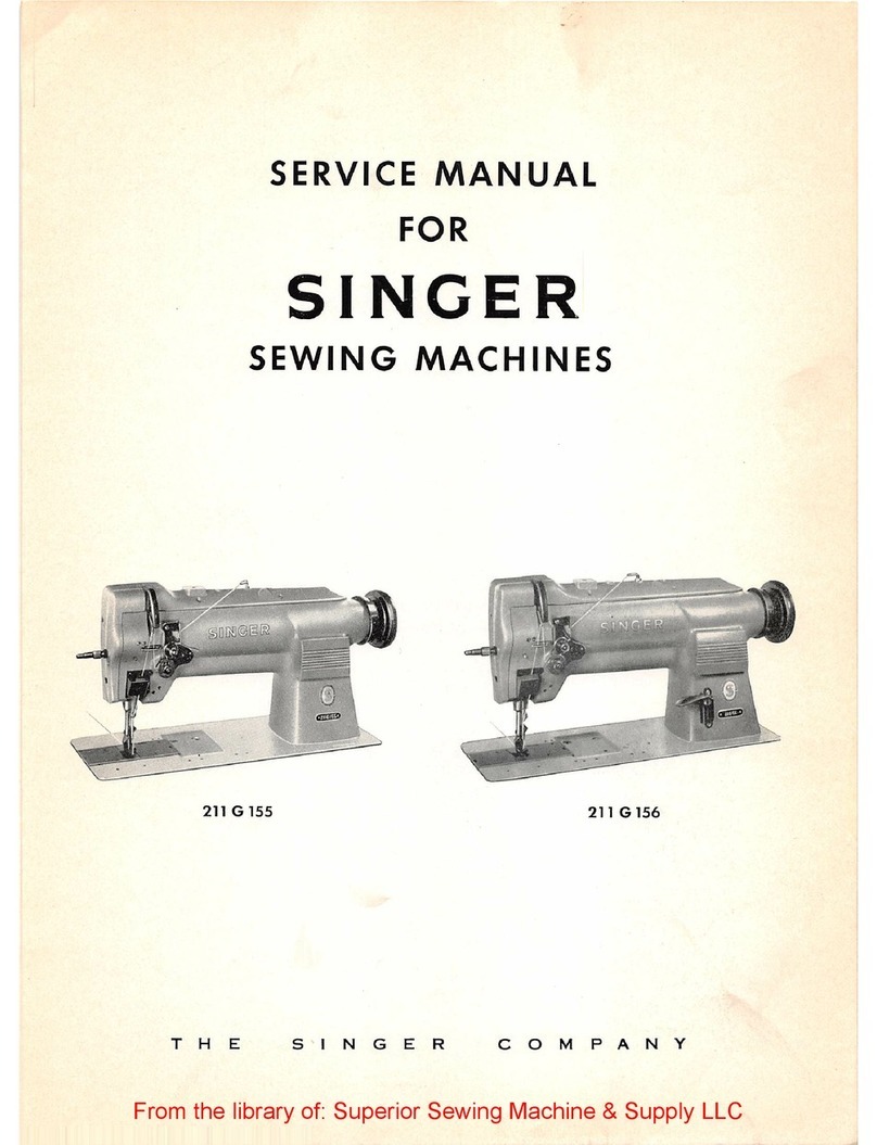
Singer 2802 User manual

358487-001 Mar./2005
Service Manual
Household Sewing
Machine
THE SINGER COMPANY
2005 SINGER BRASIL
SEWING MACHINE CO., LTD.
ALL RIGHTS RESERVED
Registered Trademark “THE SINGER COMPANY LTD.” Printed In Brazil
2802/2852 2808/2858
2809/2859 2818/2868
2802/2852 2808/2858
2809/2859 2818/2868

Revisions Records
Revision Description Approval
and date
01
Rev. n .
o
Service Manual
358487-001 Mar./2005

This manual is designed for use by trained and qualified service persons.
The SINGER COMPANY will not be responsible for any parts requiring
replacement due to natural wear or to the abuse or negligence of its use
or in the event the machine is serviced by other than a trained and
qualified service person or even if replaced parts do not meet applicable
specifications.
Service Manual
02
Rev. n .
o
358487-001 Mar./2005

03
Scope
Machine Description
Tool requirements
“Duratec” Casting
This service manual describes all of the servicing procedures,including all adjustments and parts
removal and replacement for the 2802/2852, 2808/2858, 2809/2859 and 2818/2868 models
machine. Additional information covering any production changes, improvements or changes to
parts will be made by issuing Singer service/parts bulletins.
Tubular and flat bed.
Lightweight casting.
Apollo sewing system.
Electronic triac foot speed controller.
New "FT" fabric feed system.
Vertical needle profile.
Motor concealed in bed.
Horizontal spool pin.
Auto declutching bobbin winding.
Bobbin capacity of 41 m (45 yds) minimum.
Universal presser bar pressure control.
Maximum stitch lenght 5 mm (5 s.p.i.).
Self-threading take-up lever.
Push button instant reverse.
One-way needle insertion.
Direct pattern selection.
Bed length 380 mm. (14.96 inches) without cloth plate.
Bed width 185 mm. (7.28 inches).
Bed height 83 mm. (3.27 inches).
Clearance under free arm 25,4 mm. (1.0 inch).
Free arm circunference 264 mm. (10.39 inches).
Overall height 310 mm. (12.20 inches).
Weight 7,0 kg. (15,3 lbs).
1/8" screwdriver
3/16" screwdriver
1/4" screwdriver
Philips screwdriver
8 mm. open end wrench
10 mm. open end wrench
Pliers
Wire-cutter pliers
Feeler gauge GM8092
Feeler gauge set.
1,5 mm Allen wrench
Straight tips external ring pliers (tip dia. 0,9 mm)
With the introduction of “Duratec”, selfthreading screws have been used to mount many of the
parts and assemblies to the structure. If is important that when replacing these screws, they be
threaded into the original screw threads. The proper procedure for doing this is to insert the
screw into the hole and turn the screw conterclockwise until the screw can be felt to “drop” in
place. An audible “click” may also be herad. Once the screw is properly in place, it may then be
tightened.
l
l
l
l
l
l
l
l
l
l
l
l
l
l
l
l
l
l
l
l
l
l
l
l
l
l
l
l
l
l
l
l
l
l
l
l
“Duratec”
Extralong screwdriver (5,0 mm dia. x 380 mm long)
Service Manual
General Information
Rev. n .
o
358487-001 Mar./2005

l
l
l
l
l
l
l
l
l
l
l
l
l
l
l
l
l
l
l
l
l
l
l
l
l
Parts removals and replacements.........................................................
Face plate.....................................................................................
Light bulb replacement.....................................................................
Bed bottom cover and end cover..........................................................
Needle bar.....................................................................................
Take-up lever assembly and needle bar connecting link..............................
Handwheel and shaft driver assembly....................................................
Arm shaft and horizontal bevel gear.......................................................
assembly .
Thread tension assembly....................................................................
Motor and motor belt........................................................................
Hook............................................................................................
Feed lifting lever assembly.................................................................
Feed rock shaft assembly...................................................................
Feed forked connection.....................................................................
Vertical shaft bevel gear....................................................................
Vertical shaft..................................................................................
Stitch lenght control assembly.............................................................
Pattern selector mechanism................................................................
Needle position selector lever..............................................................
Arm top cover................................................................................
Head end assembly...........................................................................
Cam stack......................................................................................
Disc follower quick out lever................................................................
Disc follower....................................................................................
Pattern selector .................................................................
Table of Contents
Section 1
06
07-08
07-08
09-10
11-12
13-14
15-16
17-18
19-20
21-22
23-24
23-24
25-26
27-28
29-30
31-32
33-34
35-36
37-38
39-40
41-42
43-44
45-46
47-48
49-50
PAGE
Service Manual
04
Rev. n .
o
358487-001 Mar./2005

l
l
l
l
l
l
l
l
l
l
l
l
l
l
l
l
l
l
l
l
l
l
l
l
l
l
l
l
l
l
l
l
Sequential order of adjustment procedures ...............................................
Vertical shaft end play .........................................................................
Bevel gear mesh and arm shaft end play ..................................................
Disc and disc follower clearance ........................................................
Cam stack radial play .....................................................................
Take-up lever and needle bar connecting link lost motion .............................
Needle bar bearings ...........................................................................
Needle bar height ..............................................................................
Needle bar pendulum timing ...............................................................
Zig-zag centralizing procedure ..............................................................
Needle location in the needle plate slot ..................................................
Needle to hook relationship ..................................................................
Maximum width zig-zag lever stop.........................................................
Needle bar safety bight stop (left side) ..................................................
Presser bar height and alignment ...........................................................
Hook drive belt tension .....................................................................
Hook timing (hook and needle synchronism) ............................................
Bobbin case position finger .................................................................
Bobbin case position plate .................................................................
Bobbin case clearance .......................................................................
Needle Thread tension .......................................................................
Bobbin winder .................................................................................
Feed rock shaft end play ....................................................................
Feed dog centralization .....................................................................
Feed dog height ..............................................................................
Feed dog throw ...............................................................................
Stitch length regulator spring tension...................................................
Motor belt tension ...........................................................................
Zero feed ....................................................................................
Lubrication....................................................................................
Flexi stitch zeroing..........................................................................
Buttonhole cutting space..................................................................
51
52-53
54-55
56-57
56-57
58-59
60-61
62-63
64-65
66-67
68-69
70-71
72-73
74-75
76-77
78-79
80-81
82-83
82-83
84-85
86-87
88-89
90-91
92-93
92-93
94-95
96-97
98-99
100-103
104-108
109-110
111-112
PAGE
Service Manual
Table of Contents
Section 2
05
Rev. n .
o
358487-001 Mar./2005


Section 1
Parts Removal and
Replacement
Service Manual
06
Rev. n .
o
358487-001 Mar./2005

A
C
Service Manual
Light Bulb Replacement
Face Plate Cover
07
Rev. n .
o
B
358487-001 Mar./2005

Removal:
Replacement:
Removal:
Replacement:
1. Raise presser foot.
2. Remove face plate cover screw (A).
3. Remove face plate cover (B) by pulling it down and laterally and then out of the
machine.
1. Replacement of the face plate cover is the same as described above, but in a reverse
order. Be sure the presser foot is in the raised position.
Turn the machine off and remove plug from outlet.
1. Remove face plate cover.
2. Push lamp (C) up and turn it clockwise.
3. The spring inside the socket, will push the lamp down and out the socket.
1. After inserting the lamp pins into the socket slots, push the bulb lamp (C) up and then
turn it gently counterclockwise.
Face Plate Cover
Service Manual
Light Bulb Replacement
08
Rev. n .
o
358487-001 Mar./2005

Service Manual
B
A
Arm Top Cover
09
Rev. n .
o
0
1
2
3
4
5
358487-001 Mar./2005
0
1
2
3
4
5

Removal:
Replacement:
1. Place bobbin winder in the “OFF” position.
2. Remove two arm top cover screws (A) and (B).
3. Remove the arm top cover by pulling it straight upwards.
1. Replacement is the same as removal in reverse order.
Arm Top Cover
Service Manual
10
Rev. n .
o
358487-001 Mar./2005

Service Manual
Bed Bottom Cover (Free Arm)
11
Rev. n .
o
A
D
B
E
C
C
F
Bed Bottom Cover (Flat Bed)
H
G
and End Cover
358487-001 Mar./2005

Service Manual
12
Rev. n .
o
Bed Bottom Cover (Free Arm)
Removal:
Replacement:
1. Remove arm top cover.
2. Remove screw (A).
3. Hold the bottom side of cover (B) and pull it out and up from machine.
1. Replacement of this cover is the same as described above, but in a reverse order.
End Cover
Bed Bottom Cover (Flat Bed)
Removal:
Replacement:
1. Remove the four screws (G).
2. Remove bed bottom cover (H).
Replacement of this bed bottom cover is the same as described above, but in a
reverse order.
1.
358487-001 Mar./2005
Removal:
Replacement:
1. Remove the bed bottom rubber feet (C).
2. Remove the screws (D).
3. Remove 8mm hex nut (E).
4. Remove bed bottom cover (F).
Replacement of this bed bottom cover is the same as described above, but in a
reverse order.
1.

Service Manual
AA
C
B
Needle Bar
13
D
E
Rev. n .
o
358487-001 Mar./2005
Service Manual
Removal:
Replacement:
1. Remove the face plate and arm top cover.
2. Remove needle by loosing the screw (B). Turn handwheel to bring the needle bar to its
position. Loose screw (A) together with the thread guide and then, remove the entire
needle clamp body. Remove also the needle bar gib (C).
3. Loosen needle bar connecting stud screw (D).
4. Draw needle bar (E) up and out of the machine.
Replacement the needle bar the same way as described above, but in a reverse order.
2- Adjust needle bar height (see pages 62-63).
1.
Needle Bar
14
Rev. n .
o
358487-001 Mar./2005

Service Manual
15
G
F
H
I
C
Rev. n .
o
Head End Assembly
E
D
358487-001 Mar./2005
A
J
B

Service Manual
Head End Assembly
16
Rev. n .
o
Removal:
Replacement:
1- Remove face plate, arm top cover and needle.
2- Loosen needle bar driving screw (A).
3- Remove presser foot (D) and presser foot screw (E).
4- Remove light socket mounting screw (H), light socket (G) and light shield (I).
5- Remove three head end mounting screws and washers (C), (F) and (J) .
6- Remove head end assembly (B).
1- Replacement is the same as removal in reverse order.
2- Adjust needle location in the needle plate slot and needle to hook relationship. (See
pages 70-71)
3- Check hook timing (See pages 80-81)and needle bar height (See pages 62-63) and adjust
if necessary.
4- Adjust presser bar alignment and height. (See pages 76-77)
358487-001 Mar./2005

Service Manual
Take-up Lever Assembly and
Needle Bar Connecting Link
17
Rev. n .
o
A
B
C
D
E
358487-001 Mar./2005

Removal:
Replacement:
1- Remove the face plate cover and arm top cover.
2- Turn hand wheel sufficiently to appear the screw (A). Loosen it. Turn again to
appear the screw (B). Loosen it also.
3- Slide take-up lever assembly (C), take-up stud (D) and needle bar connecting link (E).
1- Replacement is the same as removal in reverse order. Make sure that stud (D) is
firmly located against link (E).
2- Adjust needle location in the needle plate slot (See pages 68-69) and needle to
hook relationship (See pages 70-71).
3- Check hook timing (See pages 80-81), needle bar height (See pages 62-63) and
adjust if necessary.
4- Adjust presser bar alignment and height. (See pages 76-77)
Take-up Lever Assembly and
Needle Bar Connecting Link
Service Manual
18
Rev. n .
o
358487-001 Mar./2005

Service Manual
Handwheel and Shaft Driver Assembly
19
Rev. n .
o
E
F
G
H
358487-001 Mar./2005
A
B
C
D
This manual suits for next models
7
Table of contents
Other Singer Sewing Machine manuals

Singer
Singer 79-104 User manual

Singer
Singer 251 User manual

Singer
Singer 6416 User manual

Singer
Singer 143W2 Quick start guide

Singer
Singer 14U286B User manual

Singer
Singer 62-35 User manual

Singer
Singer 710W1 User manual

Singer
Singer 22W71 User manual

Singer
Singer 1409 User manual

Singer
Singer 20UX143 User manual

Singer
Singer 6660 User manual

Singer
Singer 66-8 User manual

Singer
Singer 221 User manual

Singer
Singer 99W130 User manual

Singer
Singer 1408 User manual

Singer
Singer FUTURA XL-400 User manual

Singer
Singer 398054 User manual

Singer
Singer 107U202 Manual

Singer
Singer 7174; 7184 User manual

Singer
Singer 3210 User manual