SINGTRONIC UHF-3000Pro User manual

Statment:The pictures in the manual are for reference only. Please refer to the real product (including but not
limited to color, size, screen display, etc.). The company has the right to change the product or specification at
any time without prior notice.
Th an k yo u for pur ch as in g ou r pro du ct ,i n or de r to ma ke
ou r products a be tt er pr ef or ma nc e, p le as e read th e
in st ru ct io ns carefully be fo re u si ng .
User Manual
True Diversity
UHF Wireless Microphone
10
AF
25
40
55
70
85
100%
A B
RF
5
10
15
20
25
30
35
40
+5 0
937000
.
10
AF
25
40
55
70
85
100%
A B
RF
5
10
15
20
25
30
35
40
+5 0
925000
.
UHF-3000Pro
925. 000 937 .000
PAGE 12
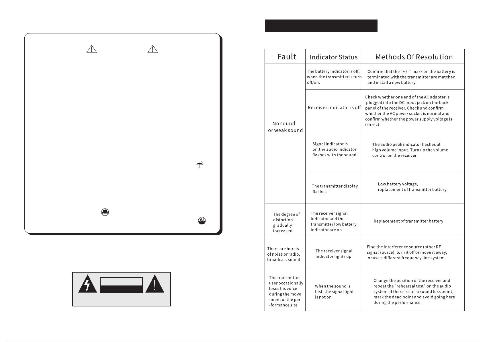
CA U T I O N S
CAUTION
RISK OF ELECTRIC SHOCK
DO NOT OPEN
AVIS:RISQUE DE CHOC ELECTRIQUE
NE PAS OUVRIR
1.Turn off the Power before installing ,removing and wiring the equipment .
Otherwise ,there will be a risk of electric shock.
2.Do not disassemble the machine, otherwise it will cause failure
3.Please use the unit within the following conditions(temperature,humidity ,
vibration ,installation direction, environment ,etc .)Otherwise,there is a
risk of fire or malfunction.
4.Do not block the ventilation holes of the equipment. Otherwise,there is a
risk of fire or malfunction.
5.Please follow the standard of the machine connection, the specified
power supply and construction method, and wire it correctly.Otherwise,
there is a risk of electric shock, fire, or malfunction.
6.Do not let the broken wire, iron power, water inside the case.Otherwise ,
there will be a risk of fire.
7.When disposing of the machine, please follow the local regulations,
Properly handled according to industrial waste.
8.The equipment must be exposed to water droplets or water splashes.
9.The equipment should be connected to the grid power outlet with
protective grounding.
10.If the power plug and appliance coupler are used as disconnect
devices, the disconnect device should kept easy to operate(Such as
knife switch or leakage switch)
11.The equipment is only suitable for safe use in areas below with an
elevation of 2000 meters.
12.The equipment is only suitable for safe use in non-climte conditions.
XII.Troubleshooting

Contents
Frequency Range
Receiver Technical Parameter
XI.Technical Parameter
PAGE 11
I. Product Instruction .............................................................(01)
II. Product Feature ...............................................................(02)
III. Standard Configuration List ..............................................(02)
IV. Panel Instruction .............................................................(03)
V. Display Screen .................................................................(04)
VI. System Operation Instruction ...........................................(05-06)
VII. Handheld Mic Instruction ................................................(07)
VIII. Lapel Mic Instruction .....................................................(08)
IX. IR Frequency Matching ...................................................(09)
X. Product Connection............................................................(10)
XI. Technical Parameter .........................................................(11)
XII. Troubleshooting................................................................(12)
Power Supply
Modulation Mode
Oscillation Mode
Frequency Stability
Sensitivity
Maximum Offset
Bandwidth
S/N Ratio
T.H.D
Frequency Response
Maximum Output Voltage
Unbalanced
Output Socket
Panel Keys
Working Distance
925-937MHz
FM
PLL Phase Locked Frequency Synthesizer
±0.0005%
When the offset is 25kHz, input 6dB μ V, S / N > 60dB
±45kHz
40MHz
>108dB
<0.4%@1KHz
65Hz~18kHz,±3dB
Balanced:-20dBB/100Ω
-4dBV/5KΩ
XLR Balance;φ6.3 Unbalance
Handheld&Lapel button switch display
About 100M(Without Obstacle)
DC12V-2A
Carrier Frequency Band
Transmitter Technical Parameter
Oscillation Mode
Harmonic Radiation
Bandwidth
Maximum Offset
Output Power
Frequency Response
Maximum Input Sound Pressure
Pickup Head
RF Power Output
Battery
Current Consumption
PLL Phase Locked Frequency Synthesizer
80MHz
±45kHz
30mW
50Hz~18kHz
130dB SPL
Handheld:Moving Coil ;Headset/Lapel:Condenser
Standard:8mW;Optional:15mW
2 AA
<150mA
<-63dBm
925-937MHz

10
AF
25
40
55
70
85
100%
A B
RF
5
10
15
20
25
30
35
40
+5 0
937000
.
10
AF
25
40
55
70
85
100%
A B
RF
5
10
15
20
25
30
35
40
+5 0
925000
.
925. 000 937 .000
Adopts leading high-tech designs : UHF transmission, real
diversity reception, dual CPU control, liquid crystal display,
metal shell, PLL technology, noise detection, etc. It has 180
frequency points adjustable and easy to use.
Microcomputer CPU control: The whole hardware circuit of the
system is controlled by microcomputer, which can carry out
frequency selection, display, mute locking, battery capacity
monitoring and other processing.
Liquid crystal display: High performance liquid crystal is used
for display, and all control menus can be displayed on the liquid
crystal screen to facilitate the control of the system.
PAGE 01 PAGE 10
Antenna
I. Product Instruction X.Product Connection
Antenna Gain
Handheld Transmitter
True Diversity Receiver
Antenna Distributor
Audio Mixer
Power Amplifier
Speaker Speaker
925.000 937.000
10
AF
25
40
55
70
85
100%
A B
RF
5
10
15
20
25
30
35
40
+50
937000
.
10
AF
25
40
55
70
85
100%
A B
RF
5
10
15
20
25
30
35
40
+50
925000
.
10
AF
25
40
55
70
85
100%
A B
RF
5
10
15
20
25
30
35
40
+5 0
937000
.
10
AF
25
40
55
70
85
100%
A B
RF
5
10
15
20
25
30
35
40
+5 0
925000
.
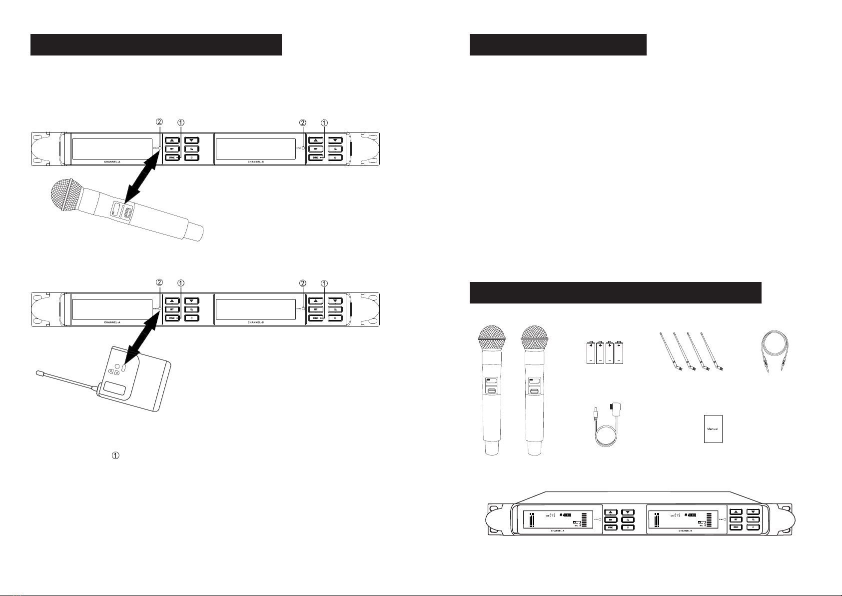
Receiver×1
PAGE 09 PAGE 02
1.Adopted UHF to avoid interference frequency;
2.Low transmission delay and long transmission distance;
3.Fully integrated chip scheme, stable product performance;
4.2 x 18 adjusted channels;
5.Enhanced wireless reception;
6.Large LCD display;
7.With automatic search for clean channels;
8.The hand microphone with intelligent mute function;
9.Electronic volume adjustment function;
10.With balanced output and mixed output.
IX.IR Frequency Matching II.Product Feature
Handheld Transmitter×2 pcs
1.5V Battery×4 pcs Antenna ×4 pcs Audio Cable×1 pcs
Power Plug×1 pcs User Manual×1 pcs
III.Standard Configuration List
An infrared transmission system.
SET
IR
1.Trun on the transmitter and receiver power;
2.Press”SYNC” key on the receiver,the receiver LED display IR flashing;
3.Face the transmitter IR window to receiver IR window,frequency matching.
The transmitter frequency and the receiver frequency will become the same
after frequency matching succeed.(If frequency matching failure,repeat the
same operation as above)
925.000
925. 000 937. 000

PAGE 03 PAGE 08
IV. Panel Instruction VIII.Lapel Mic Instruction
Front Panel Instruction
3.5inch TFT screen;
IR window;
Volume increase/Up selection Key;
Volume reduction/Down selection Key;
Press“SET” key ,through UP and Down key set receiver channel ,frequency,
press “SET”key to save after setting finish;
Scan frequency key to search the frequency automatically;
Press the “SYNC” key to match the receiver and transmitter frequency;
“Lock”key,lock the receiver screen;
Power switch.
Rear Panel Instruction
Power Socket(DC IN);
CH4 Antenna Interface;
CH3 Antenna Interface;
Audio output,3-pin interface, balance output(AF OUT BAL)(B)
Audio output,6.35mm interface, unbalance output(AF OUT UNBAL)
Audio output,3-pin interface, balance output(AF OUT BAL)(A)
CH2 Antenna Interface;
CH1 Antenna Interface;
SET
IR
Bodypack Instruction
Bodypack antenna;
Led display;
Up selection key;
Down selection key;
“SET” function key;
IR window;
Antenna Interface;
Power Switch;
Microphone interface;
Power slot.

PAGE 04PAGE 07
V.Display Screen
VII. Handheld Mic Instruction
Handheld transmitter Instruction
Pickup net;
LCD display;
IR window;
Power switch;
Battery slot.
Receiver display screen
10
AF
25
40
55
70
85
100%
A B
RF
5
10
15
20
25
30
35
40
+50
925000
.
Channel
Lock key
Microphone battery level
Microphone volume level
Audio volume level
Antenna signal level
Antenna signal receiving
status
Frequency
Microphone status
Channel number
After enabling, the panel is locked
100%
75%
50%
25%
Battery is running out,replace it asap
Display microphone volume level
Display input audio volume level
Display antenna signal level
Display frequency currently used
Display microphone connection status
When display”A”,
means antenna A signal input
When display”B”,
means antenna B signal input
925.000
PAGE 06PAGE 05
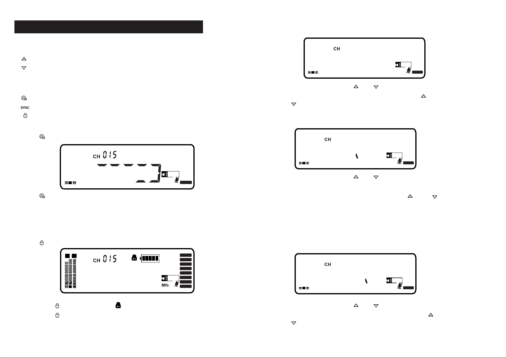
VI. System Operation Instruction
Panel function key introduction
“ ” Volume increase/Up selection key, press directly to increase volume;
“ ” Volume reduction/Down selection key, press directly to reduction volume;
“SET” Press “SET”,then through UP and Down key set receiver channel ,
frequency, press “SET”key to save after setting finish;
“ ” Scan frequency key to search the frequency automatically;
“ ” Press the “SYNC” key to match the receiver and transmitter frequency;
“ ”,lock the receiver screen;
Search frequency automatically
Press “ ” ,the receiver screen display as below:
AF
RF
5
10
15
20
25
30
35
40
+50
Press “ ” key, the system will automatically sweep the frequency, thereceiver
screenwillscrolling the digital. After display “IR”,froofreading the handheld mic
frequency, when the screen digital become white color, the operation succeed.
Lock key
Press “ ” ,the receiver screen display as below:
10
AF
25
40
55
70
85
100%
A B
RF
5
10
15
20
25
30
35
40
+50
925000
.
Long press “ ”3 seconds ,enter “ ” status,the panel will be locked.
Long press “ ”3 seconds to unlock.
Set channel manually
The receiver will display as below:
AF
RF
5
10
15
20
25
30
35
40
+50
CHAN
02
Press ”SET”,then press “ ” or “ ” to select “CHAN”as above,
press ”SET” to enter the channel setting, through “ “ and
“ “ key set receiver channel ,press “SET”key to save.
Set receiver signal intensity manually
The receiver will display as below:
AF
RF
5
10
15
20
25
30
35
40
+50
S0
02
Press ”SET”,then press “ ” or “ ” to select “SQ”as above,
press ”SET” to enter the signal intensity setting, there are
3 signals can be select “-95/-90/85”,through “ “ and “ “
key to select ,press “SET”key to save.
Noted:1.The smaller the sensitivity, the shorter the wireless receiving distance
and the stronger the anti-interference.
2.The greater the sensitivity, the longer the wireless receiving distance
and it is easy to receive other signals.
Set receiver signal intensity manually
The receiver will display as below:
Set receiver signal intensity manually
The receiver will display as below:
AF
RF
5
10
15
20
25
30
35
40
+50
FRE0
02
Set receiver signal intensity manually
The receiver will display as below:
Press ”SET”,then press “ ” or “ ” to select “FREQ”as above,
press ”SET” to enter the Frequency setting, through “ “ and
“ “ key set receiver channel ,press “SET”key to save.
Table of contents


