Sintrol Dumo Series User manual
USER MANUAL
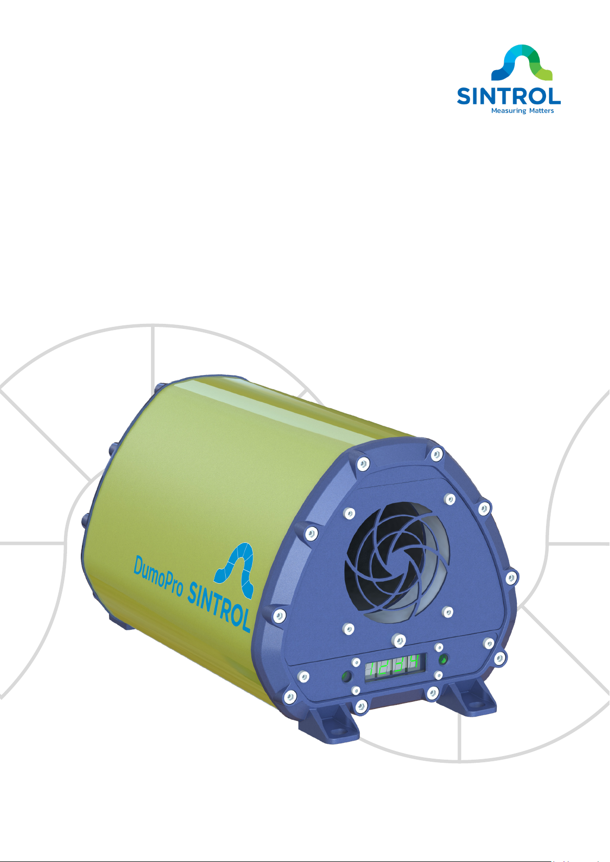
Dumo Series Ambient Dust Monitor
Model DumoPro

©2021 Sintrol.
All rights reserved.
2 (104)
Revision 4
Document information
Revision
4
Publication date:
2021-03-19
Device series:
Dumo
Applicable products:
DumoPro
Original language:
en-US
Trademarks
Modbus is a registered trademark of Schneider Electric USA Inc.
Legal disclaimer
Seller hereby disclaims any and all warranties and representations (express or implied, oral or written),
including any and all implied warranties of merchantability or fitness for any purpose whether or not
seller knows, or has reason to know, has been advised, or is otherwise in fact aware of any such purpose,
whether alleged to arise by law, by reason of custom or usage in the trade, or by course of dealing or
performance.
Purchaser understands and agrees that it shall be purchaser’s sole responsibility to ensure that all
products obtained from seller shall adhere to applicable laws, codes and standards within the territory
of use. Purchaser absolves and holds seller harmless for any alleged violations of such local laws, codes,
and standards within the territory of use.
Copyright
Subject to change without notice.
All rights reserved. ©2021 Sintrol.

©2021 Sintrol.
All rights reserved.
3 (104)
Revision 4
Contents
1 About this manual........................................5
1.1 Description of symbols..............................5
1.2 Abbreviations ............................................6
2 Safety...........................................................7
2.1 Warnings ...................................................7
2.2 Intended use .............................................8
2.3 Use in potentially explosive atmospheres 9
2.4 Conformity to standards and directives ...9
3 Product overview ....................................... 10
3.1 Product description.................................10
3.1.1 Key properties ..................................10
3.1.2 Commissioning.................................10
3.1.3 Installation........................................10
3.1.4 Settings and parameters..................11
3.2 Design drawings ......................................11
3.2.1 Dimension drawings.........................14
3.2.2 Identification ....................................16
3.3 Scope of delivery.....................................17
3.4 Features and accessories ........................17
3.4.1 Standard features.............................17
3.4.2 Optional features and accessories...18
3.5 Operating principle .................................20
3.5.1 Inductive Electrification Unit............21
3.5.2 Potential influences on measurement
results........................................................21
4 Storage ......................................................24
5 Mechanical installation ..............................25
5.1 Unpacking and inspection.......................25
5.1.1 Unpacking.........................................25
5.1.2 Inspection.........................................25
5.2 Selecting installation location .................25
5.2.1 Ambient environment......................26
5.2.2 Location............................................26
5.2.3 Distance and grid layout ..................28
5.2.4 Orientation in wireless
communication .........................................29
5.3 Installing dust monitor............................29
5.3.1 Safety precautions ...........................29
5.3.2 Installation .......................................29
6 Electrical installation.................................. 31
6.1 Electrical safety .......................................31
6.2 Cable types..............................................32
6.3 Electrical connections .............................33
6.3.1 Main board.......................................33
6.3.2 Terminal blocks ................................34
6.3.3 Grounding ........................................34
6.3.4 Power supply....................................39
6.3.5 Relays ...............................................43
6.3.6 RS-485 bus........................................46
6.3.7 Analog mA output............................50
6.3.8 Connecting with USB........................54
7 DustTool.................................................... 55
7.1 Overview .................................................55
7.2 System requirements..............................55
7.3 Main view................................................55
8 Commissioning and system setup............... 57
8.1 Auto setup...............................................57
8.1.1 Overview ..........................................57
8.1.2 Response modes ..............................57
8.1.3 Operation statuses...........................58
8.1.4 Performing Auto Setup ....................60
8.2 Changing parameters..............................60

©2021 Sintrol.
All rights reserved.
4 (104)
Revision 4
8.2.1 Main interface..................................60
8.2.2 DustTool software............................62
8.2.3 Modbus RTU and Sintrol Network
protocol.....................................................62
8.2.4 Wireless connection.........................63
8.3 Setting up device network ......................63
8.3.1 Naming devices ................................64
8.3.2 Wired device network......................64
8.3.3 Wireless device network..................66
8.3.4 Combining wired and wireless
connections in a network..........................68
9 Operation .................................................. 69
9.1 Main interface.........................................69
9.2 Relay, LED and display functional logic...70
9.2.1 Operation statuses...........................70
9.2.2 Relay logic ........................................71
9.2.3 LED and display logic........................72
9.3 Response modes .....................................73
9.4 Parameters..............................................74
9.4.1 Overview ..........................................74
9.4.2 Parameter 1: Display unit ................76
9.4.3 Parameter 2: Signal averaging time.76
9.4.4 Parameter 3: Measurement range ..76
9.4.5 Parameter 4: ALERT threshold.........77
9.4.6 Parameter 5: ALARM threshold.......78
9.4.7 Parameter 6: Alarm delay time........79
9.4.8 Parameter 9: Zero/Span check
interval ......................................................79
9.4.9 Parameter 10: Command parameter
...................................................................79
9.4.10 Parameters 11 to 14: Displaying
measurement results in mg/m3................81
9.4.11 Parameters 15 and 16: IEU to 20 mA
scaling........................................................83
9.4.12 Parameter 17: Firmware version... 84
9.5 Troubleshooting...................................... 84
9.5.1 Resetting RS-485 settings to factory
defaults .....................................................84
9.5.2 Error codes in FAULT mode .............85
9.5.3 Display indicates “- -.- -“ .................. 86
9.5.4 Display indicates “[n] - - -” ............... 87
9.5.5 No output signal ..............................87
9.5.6 No response after Auto Setup .........87
10 Maintenance and inspection.....................88
10.1 Safety precautions ................................88
10.2 Maintenance and inspection interval... 89
10.2.1 Cleaning supplies ...........................90
10.2.2 Maintenance of Teflon-coated probe
..................................................................90
10.3 Cleaning flow chamber and sensor probe
......................................................................90
10.4 Replacing malfunctioning fan ...............92
10.5 Returns..................................................96
11 Recycling and disposal ..............................97
11.1 Packaging ..............................................97
11.2 Device ...................................................97
12 Specifications ...........................................98
Appendix A: ISO 9001 certificate ................. 100
Appendix B: Modbus RTU registers.............. 101
Notes .......................................................... 103
©2021 Sintrol.
All rights reserved.
5 (104)
Revision 4
1About this manual
This user manual contains the installation, commissioning, operating and maintenance instructions for
Dumo series ambient dust monitor model DumoPro. Read this manual carefully before using the device.
This manual is an important part of the product, and it must always be available for reference to all
personnel installing, commissioning, operating or performing maintenance on the device. In case the
manual is lost or damaged, request a new copy from the manufacturer or an authorized distributor.
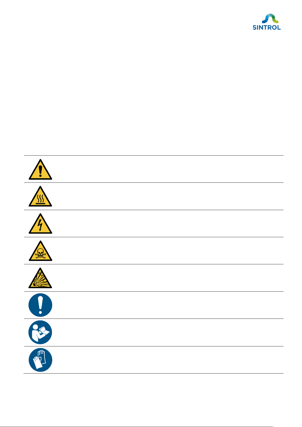
1.1 Description of symbols
These symbols are used to alert you to any potential personal injury hazards, and to provide information
on how to avoid them. Obey all safety messages that use these symbols to avoid possible injury or
death. Symbols that provide additional information about using and handling the product are also
described here.
Symbol
Description
General warning symbol.
Hot surface.
Electric hazard.
Toxic hazard.
Explosion hazard.
Important or useful information related to installing, maintaining or operating the device.
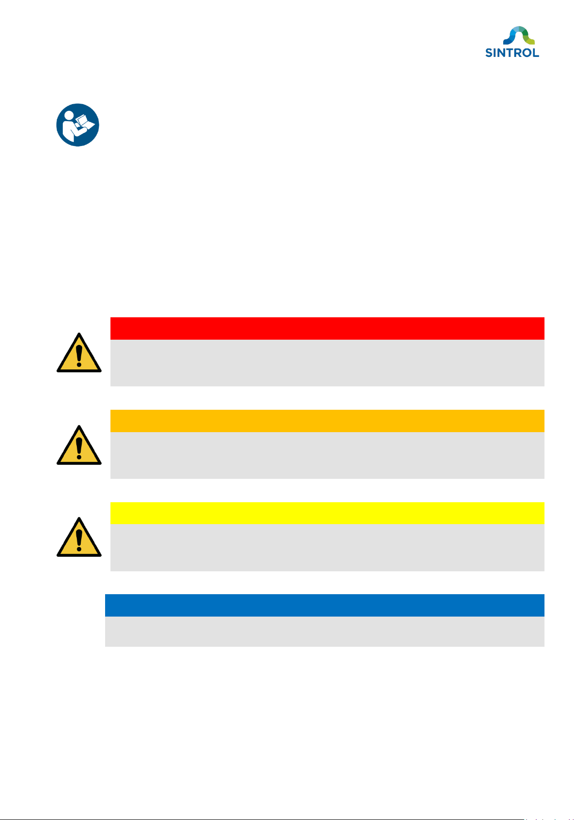
Read the user manual before doing a procedure or operating the device.
Wear protective gloves.
©2021 Sintrol.
All rights reserved.
6 (104)
Revision 4
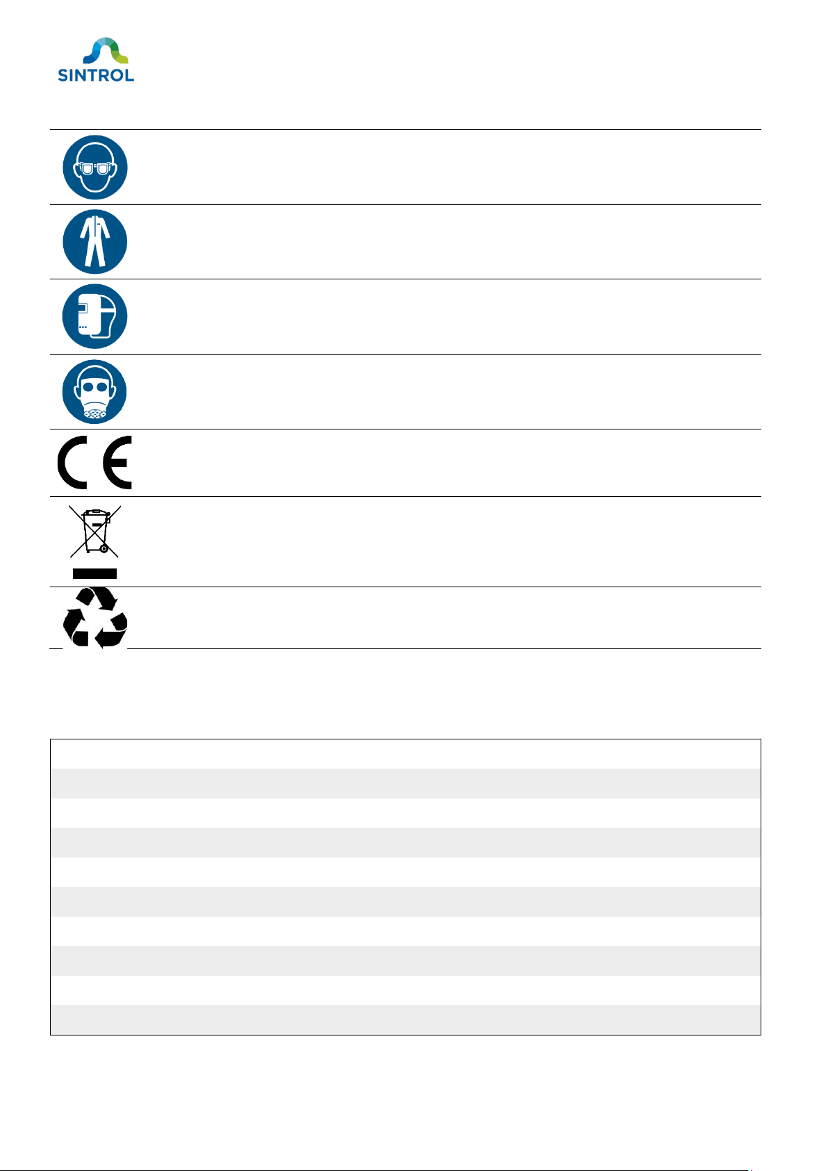
Symbol
Description
Wear protective glasses.
Wear protective overalls.
Wear a welding mask.
Wear respiratory protection.
CE marking indicates that the device has been designed and manufactured to meet all
applicable health, safety and environmental protection standards required for products
sold in the European Union.
Electronic devices that are marked with this symbol must not be disposed of with general
waste. If a defective or broken-down device cannot be repaired, it must be recycled and
disposed of in accordance with WEEE directive (2012/19/EU) or other applicable local
regulations.
This symbol indicates waste material that must be recycled.
1.2 Abbreviations
Abbreviation
Explanation
ID Inside diameter
IEU Inductive electrification unit
MB Modbus
MEC Minimum explosible concentration
OD Outside diameter
RF Radio frequency
RH Relative humidity
SNT Sintrol Network
SSR Solid-state relay
TSP Total suspended particles
©2021 Sintrol.
All rights reserved.
7 (104)
Revision 4
2Safety
Read this chapter carefully before handling the device in any way.
In addition, read all safety notes before work steps and other instructions.
Only trained and qualified personnel can install, commission, operate and perform maintenance on the
device. All personnel must read and understand this manual and follow its instructions accurately.
Failure to follow the safety instructions and safety precautions can result in serious injury or death.
If you encounter any unexpected situations during the intended use of the device that are not described
in this manual, contact the manufacturer or an authorized distributor.
In addition to the safety instructions described in this manual, the personnel using the device must
follow all applicable country- and industry-specific safety standards and regulations.
2.1 Warnings
DANGER!
“DANGER” indicates a hazard with a high level of risk, which will result in death or
serious injury if not avoided.
WARNING!
“WARNING” indicates a hazard with a medium level of risk, which can result in death
or serious injury if not avoided.
CAUTION!
“CAUTION” indicates a hazard with a low level of risk, which can result in minor or
moderate injury if not avoided.
NOTICE
“NOTICE” indicates a situation with a risk of equipment damage.

©2021 Sintrol.
All rights reserved.
8 (104)
Revision 4
2.2 Intended use
This device is designed for continuous measuring of total suspended particles (TSP) in ambient air. The
intended use is as described in this user manual. Any other use is considered improper and can result in
injury or equipment damage.
The manufacturer or distributor cannot be held liable for any damage, injury or financial
loss resulting from improper use.
The device must not be modified or repaired in any way that is not specifically described in this manual.
Do not perform any mechanical or electrical repairs without contacting the manufacturer or an
authorized distributor. Only original Sintrol parts can be used for repairs. If third-party spare parts are
used, the manufacturer cannot guarantee safe operation of the device.
Before installing and commissioning the device, carefully inspect it for any damage or defects. Do not
use the device if it is damaged, or if the power supply is defective. Return damaged device to the
manufacturer or an authorized distributor.
Non-compliance with any of these conditions immediately voids the warranty, and the manufacturer’s
responsibility no longer applies.
Wear appropriate protective gloves at all times when installing the device.
DANGER!
Explosion hazard
The device is not UL/CSA or IECEx/ATEX certified. Do not use the device in potentially
explosive atmospheres.
WARNING!
Use in critical applications
Improper use in critical applications can lead to hazardous situations or have severe
adverse health effects. Such critical applications include, but are not limited to:
•Health protection
•Emission monitoring
•Process control
•Fire and explosion prevention

©2021 Sintrol.
All rights reserved.
9 (104)
Revision 4
Many factors can affect the operation of the dust monitoring system. These factors can include, for
example, dust particle size, dust material, and operator error. Because of this, an industry specialist must
evaluate and approve the suitability of Sintrol products for any given dust monitoring system. This is
particularly true when the instruments are only a component in a larger monitoring system, or when
they are used in critical applications.
2.3 Use in potentially explosive atmospheres
DANGER!
Explosion hazard
The device is not UL/CSA or IECEx/ATEX certified. Do not use the device in potentially
explosive atmospheres.
An ATEX-certified model of the device is available. Only ATEX-certified models can be used in potentially
explosive atmospheres.
If you have ordered ATEX-certified device, read the supplementary ATEX safety
instructions carefully before installing, commissioning, operating or performing
maintenance on the device.
2.4 Conformity to standards and directives
This device has been designed and manufactured to comply with the requirements of ISO 9001:2015
standard related to quality management. See Appendix A for ISO 9001 certificate.
This device has been designed and manufactured to comply with the following standards and directives:
•EN 61326-1:2012
•UL 61010-1, 3rd edition, 19 July 2019
•CSA 22.2 NO 61010-1, 3rd edition, 2017
•ROHS Directive 2011/65/EU (RoHS II)

©2021 Sintrol.
All rights reserved.
10 (104)
Revision 4
3Product overview
3.1 Product description
This device is designed for continuous measuring of total suspended particles (TSP) in ambient air. It is
an ideal solution for industrial applications where a disruption in normal operations can result in an
increase in dust particle concentration in ambient air, which can cause further equipment malfunction or
even pose a risk to worker health.
The operating principle is based on inductive electrification technology, where particles interacting with
an isolated probe induce a signal that is transmitted to the monitoring system. The normal dust level is
determined during commissioning, and the signal generated by the sensor is then scaled in proportion to
this baseline level when the dust level fluctuates.
The device is intended for use in non-condensing environments. The sensor does not
distinguish liquid droplets from dust particles. If the measured airflow contains liquid
droplets, the measurement results are inaccurate.
The device has a local user interface with six keys and a 7-segment display with four digits for indicating
measurement results and device status.
For detailed technical data, see chapter Specifications.
3.1.1 Key properties
Table 1: Key properties of a standard device
Enclosure: Aluminum and stainless steel (316L)
Probe material: Stainless steel (316L)
Insulation material: Teflon
Output signal: •4 ... 20 mA
•
2 × Independent solid-state relays
Communication protocol: •
Modbus RTU
•
Sintrol network
Ambient temperature −40 ... 60 °C (−40 ... 140 °F)
3.1.2 Commissioning
Commissioning is easy with Auto Setup feature, which determines the baseline dust level and sets up
two alarm thresholds that are proportional to the baseline. An alarm is triggered when the dust
concentration exceeds a configured threshold.
3.1.3 Installation
The device is installed by simply securing it to the installation location with four screws through the
built-in mounting feet. Mounting feet are suitable for standard wall, ceiling and tabletop installations.
©2021 Sintrol.
All rights reserved.
11 (104)
Revision 4
Optionally, a mounting arm or mounting bracket is available for installing the device in alternative angles
and orientations.
3.1.4 Settings and parameters
You can access and change the device settings and parameters with the local display that has six keys
and a 7-segment display with four digits. Additionally, you can connect the device to a computer using
USB, RS-485 bus or an optional radio frequency (RF) communication, and change the parameters using
complementary DustTool software. You can download DustTool free of charge at
https://sintrol.com/product/dusttool/.
3.2 Design drawings
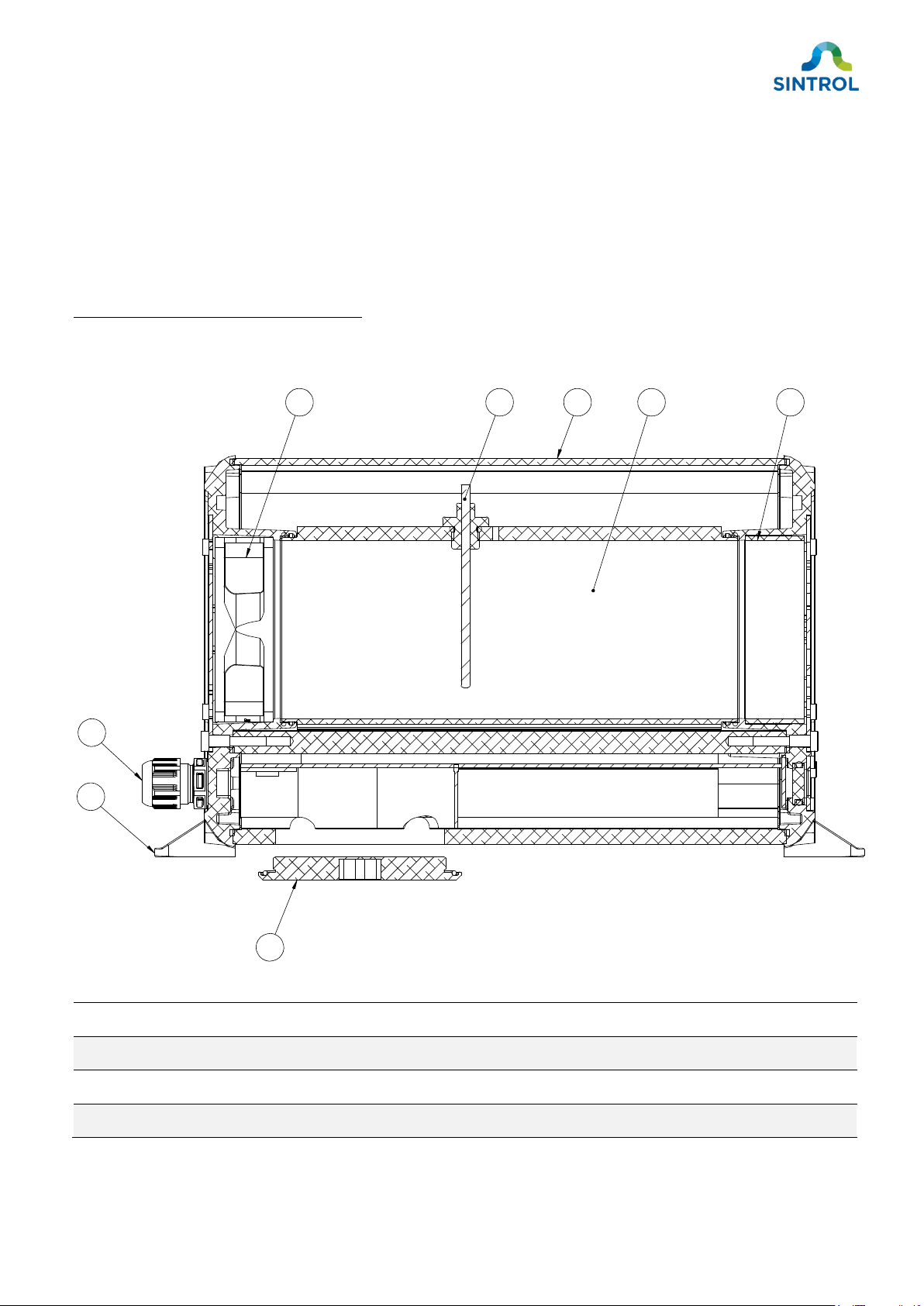
Figure 1: Side view of the dust monitor
①Fan ⑤Internal flow chamber extension
②Sensor probe ⑥M16 cable glands
③Aluminum enclosure ⑦Mounting feet
④Internal flow chamber ⑧Terminal cover
6
5
14
7
3
2
8
©2021 Sintrol.
All rights reserved.
12 (104)
Revision 4
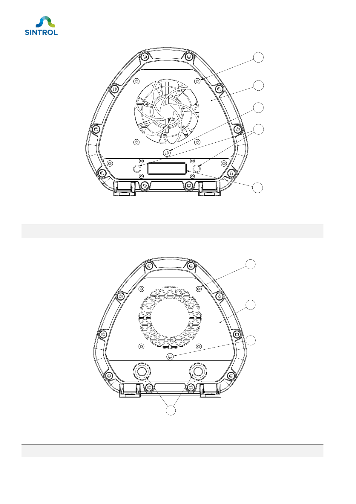
Figure 2: Front view of the dust monitor
①Bolt, hex 4 mm ④Status LEDs / magnetic switches
②
Front plate ⑤7-segment display
③Bolt, hex 5 mm
Figure 3: Rear view of the dust monitor
①
Bolt, hex 4 mm ③Bolt, hex 5 mm
②
Rear plate ④M16 cable glands
5
4
2
1
3
2
1
4
3

©2021 Sintrol.
All rights reserved.
13 (104)
Revision 4
Figure 4: Electrical connections on the main board
①
Mode selector key ⑥Solid-state relay terminal
②AUTOSETUP key ⑦RS-485 bus
③RS-485 terminator switch ⑧Analog mA output
④Navigation keys ⑨Ground connection
⑤24 V DC power supply terminal ⑩Micro-B USB port
8
3
2
5
1 4
76 9
10
©2021 Sintrol.
All rights reserved.
14 (104)
Revision 4
3.2.1 Dimension drawings
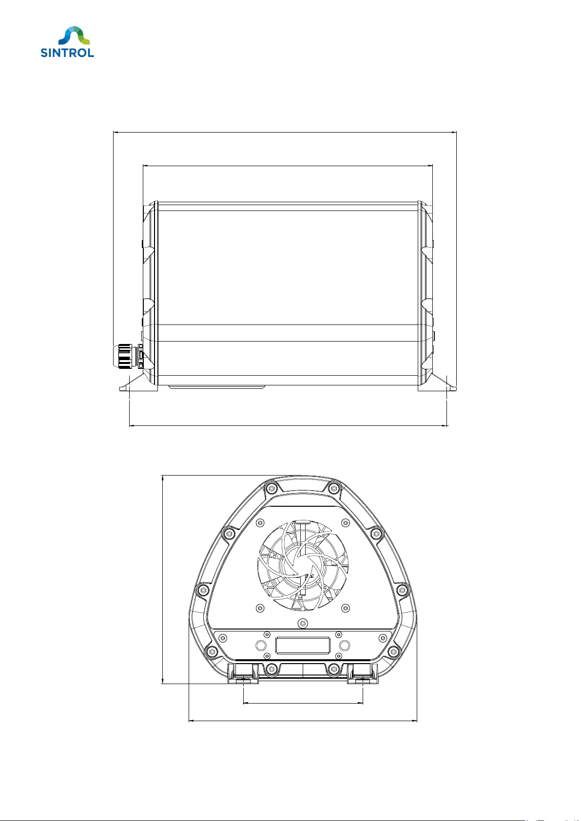
Dust monitor side view
Figure 5: Side view dimensions of the enclosure
Dust monitor front view
Figure 6: Front view dimensions of the enclosure
290.00 mm [11.42 in]
265.00 mm [10.43 in]
313.50 mm [123.43 in]
191.00 [7.52 in]
100.00 [3.94 in]
174.00 [6.85 in]

©2021 Sintrol.
All rights reserved.
15 (104)
Revision 4
Terminal cover
Figure 7: Terminal cover dimensions
Mounting bracket
Figure 8: Mounting bracket dimensions
Mounting bracket is attached to the device using the 5mm hex bolts on the outer edge
of the device enclosure. This enabled the device to be installed in various orientations.
60.00 mm [2.36 in]
35.00 mm [1.38 in]
88.00 mm [3.46 in]
12.80 mm [5.04 in]
27.00 mm [1.06 in]
52.00 mm [2.04 in]
277.00 mm [10.91 in]
65.00 mm [2.56]
65.00 mm [2.56]
©2021 Sintrol.
All rights reserved.
16 (104)
Revision 4
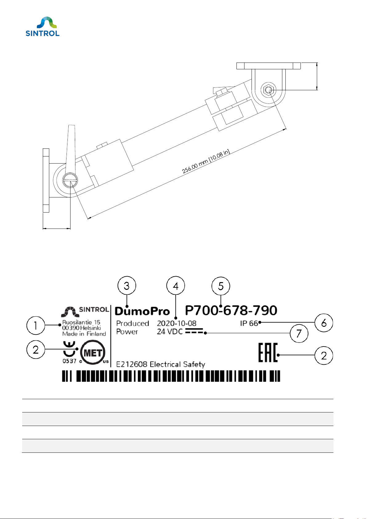
Mounting arm
Figure 9: Mounting arm dimensions
3.2.2 Identification
Identification label is located on the bottom of the device.
Figure 10: Identification label
①Manufacturer details ⑤Serial number
②Approvals ⑥IP rating
③Device model ⑦Power supply specifications
④Production date
32.00 mm
[1.26 in ]
32.00 mm
[1.26 in]

©2021 Sintrol.
All rights reserved.
17 (104)
Revision 4
3.3 Scope of delivery
A standard delivery includes one DumoPro ambient dust monitor and this user manual.
Figure 11: Standard delivery
3.4 Features and accessories
3.4.1 Standard features
A standard delivery includes the following features:
Table 2: Overview of standard features of DumoPro dust monitor
Feature
✓=Standard ⚪=Optional
Rugged IP66-rated pressure-casted aluminum enclosure
✓
Bicolor (green and red) LEDs for status indication*
✓
Auto Setup function for easy commissioning
✓
Mode selector key with user-selectable FAST, MEDIUM and SLOW response modes
✓
Two independent solid-state relays to indicate dust alert and dust alarm
✓
USB interface
✓
DustTool software for easy calibration and setup
✓
RS-485 bus for integration into existing control systems using Modbus RTU, and for connecting
multiple devices in parallel using Modbus RTU or Sintrol Network protocol
✓
Main interface with six keys and a 7-segment display with four digits for local measurement
result and status indication
✓
Active and isolated 4 ... 20 mA output in accordance with NAMUR NE43
✓

©2021 Sintrol.
All rights reserved.
18 (104)
Revision 4
Feature
✓=Standard ⚪=Optional
Zero/span check with automatic drift compensation
✓
Possibility to program the display to show dust concentrations in mg/m3
✓
Magnetic switches for easy Auto Setup and mode selection
⚪
Wireless network capability to reduce cabling costs**
⚪
* When green and red LEDs are ON at the same time, the color appears yellow or orange
** Requires radio frequency (RF) model. RF antenna cannot be retrofitted to non-RF models.
3.4.2 Optional features and accessories
The device can be customized to meet the specific requirements for various applications and process
conditions.
Mounting bracket
The device can be installed in multiple angles and orientations with an optional mounting bracket that is
attached to the device with screws located on the edges of the device enclosure. The bracket allows the
device to be installed directly on a wall. Furthermore, the mounting bracket can be ordered with DIN rail
holders.
The mounting bracket allows for more flexible installation configurations than the standard built-in
mounting feet. For example, with the mounting bracket it is possible to mount the device on a ceiling so
that the display is still in the correct orientation.
Figure 12: Mounting bracket

©2021 Sintrol.
All rights reserved.
19 (104)
Revision 4
①Mounting bracket ④2× Set screws, Dog Point M5
②
2× DIN rail holders (optional) ⑤2× Hex nuts M5
③8× Screws, ISO 7045 M3 (optional) ⑥2× WDS Tommy Bar Screws
Mounting arm
Part number: MC901167
The flexible mounting arm allows the device to be installed in various angles and orientations. It also
makes repositioning the device easy and leaves the terminal cover exposed, so it is possible to access the
main board and make configuration changes locally.
Figure 13: Mounting arm
The arm has two adjustable joints that can also be rotated around their center axis. The device enclosure
has built-in holes on the bottom side, where the mounting arm can be attached in 90° steps.
Probe coating
The sensor probe can be equipped with a protective Teflon coating that is suitable for wet conditions in
non-hazardous areas.
Magnetic switch
If magnetic switches are enabled on your device, you can use a magnetic key to initiate Auto Setup
procedure or change the response mode of the device without having to access the main board.
Wireless communication
A standard device communicates with a monitoring system or PC with signals that are transmitted
through physical wires. The device can be equipped with a radio frequency (RF) antenna to enable
wireless communication.
©2021 Sintrol.
All rights reserved.
20 (104)
Revision 4
The device must be ordered with RF capability. Non-RF models cannot be retrofitted
with the RF antenna after delivery.
Accessories
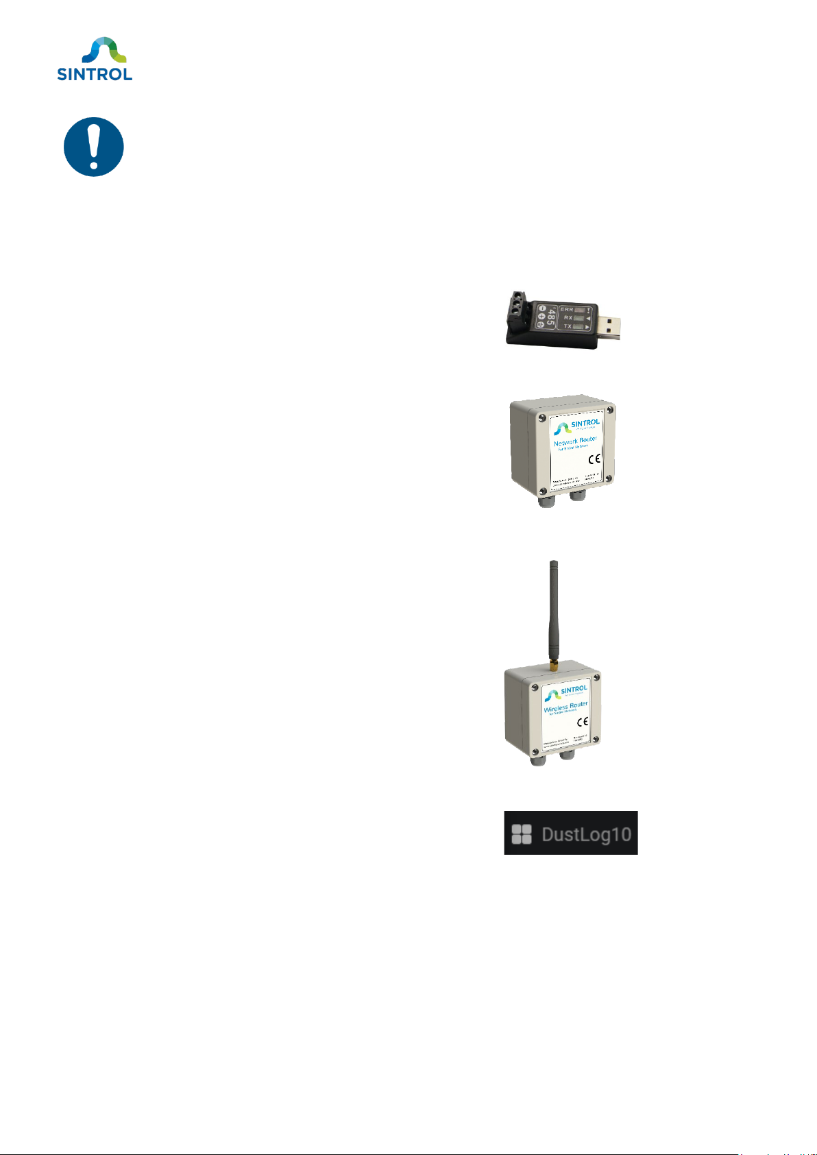
The device can be ordered with the following optional accessories:
RS-485 to USB converter for connecting the device to a
computer using Sintrol Network protocol.
Part number: EC900041
Network Router for setting up device chains and networks.
Part number: PC900091
Wireless Router for setting up wireless device networks.
Part number: PC900090
DustLog 10 reporting software for additional data logging and
reporting options.
3.5 Operating principle
The device is designed for continuous measuring of total suspended particles (TSP) in ambient air. The
instrument has a built-in fan that draws a constant flow of dust particles through the internal flow
chamber. Dust particles flowing through the chamber interact with the internal sensor probe. This
induces a signal, which is then transferred to a monitoring system, for example a computer running a
monitoring software. The underlying technology is called “inductive electrification”. This technology is
This manual suits for next models
1
Table of contents
Other Sintrol Measuring Instrument manuals

Popular Measuring Instrument manuals by other brands

Universal Laser Systems
Universal Laser Systems VLS2.30 Setup guide

HunterLab
HunterLab ColorFlex EZ manual

GMC
GMC Camille Bauer SINEAX DM5000 operating instructions

Mavic
Mavic Wintech ES2007 manual

Innova
Innova Automotive DMM owner's manual

Keysight Technologies
Keysight Technologies E5055A SSA-X installation guide


