Sintrol S300 Series User manual

User Manual
IMPORTANT
READ CAREFULLY BEFORE USE
READ USER MANUAL FOR OPTIONAL PRODUCTS IF APPLICABLE
KEEP FOR FUTURE REFERENCE
S300 Series, comprising the models S303 and S304
Date: 1st February 2019
Version: 2.0

Page 2 | 45
Table of Contents
1 General Information.................................................................................................................................. 5
1.1 Reading and storing the user manual................................................................................................. 5
1.2 Checking the S303 or S304 and package contents.............................................................................. 5
1.3 Overview of the life cycle operation .................................................................................................. 5
1.4 Explanation of symbols...................................................................................................................... 6
2 General safety instructions........................................................................................................................ 7
3 Intended use............................................................................................................................................. 7
4 S303 and S304 Overview ......................................................................................................................... 10
4.1 Standard Scope of delivery .............................................................................................................. 10
4.2 Accessories, and options ................................................................................................................. 11
4.3 Illustrations of components and dimensions.................................................................................... 12
5 Principle of operation, physical effects, and limitations ........................................................................... 13
5.1 Influence of particle material........................................................................................................... 13
5.2 Particle size ..................................................................................................................................... 13
5.3 Linearity, maximum concentrations, and calibration........................................................................ 14
5.4 Influence of relative humidity RH %, condensation, and droplets in the measurement gas .............. 14
5.5 Influence of ambient temperature................................................................................................... 14
5.6 Influence of flow velocity................................................................................................................. 15
5.7 Special dusts.................................................................................................................................... 15
6 Mechanical Installation ........................................................................................................................... 16
6.1 Selecting the installation location...................................................................................................... 16
6.2 Installing the sensor ........................................................................................................................ 17
7 Electrical Installation and Wiring ............................................................................................................. 18
7.1 Grounding and usage of grounded power supply............................................................................. 18
7.2 Connecting the voltage supply......................................................................................................... 19
7.3 Connecting Relays ........................................................................................................................... 19
7.4 Connecting via USB.......................................................................................................................... 20
7.5 Connecting the mA-output .............................................................................................................. 20
7.6 Connecting the RS-485 bus .............................................................................................................. 21
7.7 Connecting a RS485 Network........................................................................................................... 22
7.8 Connecting mA output of a flow speed meter (S304 only) ............................................................... 22
8 Parametrization and calibration .............................................................................................................. 23
8.1 Relay, LED and Display functional logic ............................................................................................ 23
8.2 Auto setup description .................................................................................................................... 25
8.3 General usage of the Display and 4-Key user interface (S303 and S304) ........................................... 26

Page 3 | 45
8.4 Parameter table for the local display (S303 or S304) ........................................................................ 27
8.4.1 Parameter 1: Display scale ....................................................................................................... 27
8.4.2 Parameter 2: Averaging time [sec]: .......................................................................................... 27
8.4.3 Parameter 3: 20 mA scaling (Range setting) ............................................................................. 27
8.4.4 Parameter 4: Alarm limit A [%] of Range .................................................................................. 29
8.4.5 Parameter 5: Alarm limit B [%] of Range .................................................................................. 29
8.4.6 Parameter 6: Alarm delay time [sec] ........................................................................................ 29
8.4.7 Parameter 7: Flow velocity in [m/s] at 4 [mA] (S304 only) ...................................................... 29
8.4.8 Parameter 8: Flow velocity in [m/s] at 20 [mA] (S304 only) ...................................................... 29
8.4.9 Parameter 9: Zero & Span check interval (S304 only) ............................................................... 30
8.4.10 Parameter 10: Command parameter........................................................................................ 30
8.4.11 Parameter 11: Display Intercept “a” (Integer) -99...099 [mg/m3] ............................................. 31
8.4.12 Parameter 12: Display Intercept “a” (Decimal) 000...999 [mg/m3] ........................................... 32
8.4.13 Parameter 13: Display Slope “b” (Integer) 000...999 [mg/m3/mA] ........................................... 32
8.4.14 Parameter 14: Display Slope “b” (Decimal) 000...999 [mg/m3/mA].......................................... 32
8.4.15 Parameter 15: 20 mA scaling in 000…999 [IEU] x 1 000 000 (S304 only) ................................... 32
8.4.16 Parameter 16: 20 mA scaling in 000…999 [IEU] x 1 000 (S304 only) .......................................... 32
8.4.17 Info: Firmware Version ............................................................................................................ 32
9Sintrol DustTool Software......................................................................................................................... 33
9.1 PARAMETERSS tab........................................................................................................................... 34
10 Wireless connectivity of S303 or S304 RF models ................................................................................ 35
11 Cleaning and Maintenance .................................................................................................................. 37
12 Troubleshooting.................................................................................................................................. 38
12.1 No output signal.............................................................................................................................. 38
12.2 No response after auto setup .......................................................................................................... 38
13 Technical Data..................................................................................................................................... 39
14 Authorized Distributor and Service Center Information ....................................................................... 40
15 Appendix............................................................................................................................................. 41
15.1 ISO 9001 certificate ......................................................................................................................... 41
15.2 MODBUS RTU register map ............................................................................................................. 42
16 Notes .................................................................................................................................................. 45
17 Disposal .............................................................................................................................................. 45
17.1 Disposal of packaging ...................................................................................................................... 45
17.2 Disposal of the S300 Series .............................................................................................................. 45
18 Acknowledgements............................................................................................................................. 45

Page 4 | 45
List of Figures
Figure 1: Inductive Electrification Technology ................................................................................................ 13
Figure 2: Illustration of uncalibrated measuring behavior............................................................................... 14
Figure 3: Effect of Ambient Temperature ....................................................................................................... 14
Figure 4 Influence of Flow velocity.................................................................................................................. 15
Figure 5 Recommended distance to duct bends (D = Duct diameter)............................................................... 16
Figure 6 Installation in a squared duct............................................................................................................. 17
Figure 7 Installation in a round duct................................................................................................................ 17
Figure 8 Wrong socket installation .................................................................................................................. 17
Figure 9 Connecting 24 VDC Figure 10 Connecting 80-240 VAC ................................................................... 19
Figure 11 Connecting Relays ........................................................................................................................... 19
Figure 12 mA loop connection ........................................................................................................................ 20
Figure 13 RS485 connection to DustTool ........................................................................................................ 21
Figure 14 RS485 Connection to Modbus RTU Master ...................................................................................... 21
Figure 15 Connecting a RS485 Network........................................................................................................... 22
Figure 16 Connecting mA output of a flow speed meter (S304 only) ............................................................... 22
Figure 17 Settings after Auto setup ................................................................................................................. 25
Figure 18Example for display calibration......................................................................................................... 31
Figure 19: DustTool main window .................................................................................................................. 34
Figure 20: Sintrol Network Example ............................................................................................................... 36

Page 5 | 45
1General Information
1.1 Reading and storing the user manual
This user manual accompanies the S303 and S304 dust measuring instruments and contains important
information on installation, setup, calibration, and handling.
Before using the S303 or S304, read the user manual carefully. This particularly applies to the safety
instructions. Failure to do so may result in personal injury or damage to the S303 or S304. This user manual
must be accessible to those tasked with the installation and operation of the S303 or S304.
Store the user manual for further use. Make sure to include this user manual when passing the instrument on
to third parties.
1.2 Checking the S303 or S304 and package contents
Risk of damage!
If you are not cautious when opening the packaging with a sharp knife or
other pointed object, you may quickly damage the instrument.
Be careful when opening and removing the instrument from the packaging.
1. Take the instrument out of the packaging.
2. Check to make sure that the delivery is complete (see 4.1 Standard Scope of delivery).
3. Check whether the S303 or S304 or individual parts are damaged. If this is the case, do not
use the instrument and contact the Sintrol Customer Service Department.
1.3 Overview of the life cycle operation
After unpacking the instrument, the whole life cycle operation shall be handled as follows:
Choose the appropriate installation location (see chapter 6 Mechanical Installation)
Install the instrument mechanically (see chapter 6 Mechanical Installation)
Install the instrument electrically (see chapter 7 Electrical Installation and Wiring)
Run Auto setup at normal conditions while Filtration system is intact and production running (see
chapter 8.2 Auto setup description)
Change parameters and calibrate the instrument if necessary by using the local user interface or any of
the Sintrol software (see chapter 8.4 Parameter table for the local display (S303 or S304) or chapter 9
Sintrol DustTool Software)
Use the instrument according to this manual
Clean and maintain the instrument periodically (see chapter 11 Cleaning and Maintenance)
If required do troubleshooting (see chapter 12 Troubleshooting)
If you relocate the instrument repeat the whole installation, Auto setup and calibration procedure
At the end of lifetime dispose the Instrument according to this manual (see chapter 17.2 Disposal of
the S300 Series)

Page 6 | 45
1.4 Explanation of symbols
The following symbols and signal words are used in this user manual, on the S300 Series, or on the packaging.
This symbol indicates a hazard, a hazardous situation, a precaution to
avoid a hazard, a result of not avoiding a hazard or a combination of
them.
This signal symbol/word designates a hazard with a high degree of
risk, which will result in death or severe injury if not avoided.
This signal symbol/word designates a hazard with moderate risk,
which may result in death or severe injury if not avoided.
This signal symbol/word designates a hazard with low risk, which may
result in minor or moderate injury if not avoided.
This signal word warns of possible damage to property.
This symbol provides you with useful additional information on
handling and use.
Label for waste materials intended for recycling.
Electrical products may not be disposed of with household or other
garbage. Applicable in the European Union and other European
countries with separate collection systems of recyclable materials.
This instrument conforms to the following standards:
IEC 60079-0:2017
EN 60079-11:2012, EN 60079-31:2014
EN 61010-1:2001 Safety, LVD
EN 61326-1 A1 (1998) Electromagnetic Compatibility EMC
RoHOS2: Directive 2011/65/EU of the European Parliament and of the
Council of 8 June 2011 on the restriction of the use of certain
hazardous substances in electrical and electronic equipment Text with
EEA relevance.

Page 7 | 45
2General safety instructions
Only use the instrument as described in this user manual. Any other use is considered improper and may result
in damage to property or persons.
The manufacturer or vendor cannot be held liable for damages or injury or loss incurred through improper or
incorrect use.
These models are NOT UL/CSA or IECEX/ATEX certified and CANNOT be used in
explosion risk areas. Chose other model if required.
This product is intended for skilled technicians and trained and certified
operators. Make sure the S300 Series is only operated by qualified personnel.
Electrical installation is only to be performed by qualified personnel.
Children may not install, operate, or maintain the S300 Series. Make sure that
children do not play with the plastic wrapping. They may get caught in it when
playing and suffocate.
Do not modify, alter, or remove parts of the S303 or S304 in any way, without
prior written authorization from the Sintrol Customer Service Department.
Do not use the instrument if it is damaged or if the power cord or plug is
defective.
For repairs always contact Sintrol authorized service partners. Do not perform
any mechanical or electrical repairs without prior consultation of Sintrol
authorized service partners
Only original Sintrol parts may be used for repairs. This device contains electrical
and mechanical parts which are essential for providing protection against sources
of danger.
3Intended use
S303 and S304 can be used in outdoor or indoor operations and is primarily meant to be used at non-
condensing conditions inside the duct or pipe. (The instrument will recognize droplets as particles and
therefore cannot distinguish between water droplets and dust).
It is ideal for applications where any disruption in normal operation may result in a variance in particle
concentration in the process such as filter leak detection, process measurements or emissions monitoring in
stacks. Sintrol S303 or S304 is the perfect instrument for monitoring the efficiency of this dust removal
process.
SELLER HEREBY DISCLAIMS ANY AND ALL WARRANTIES AND REPRESENTATIONS (EXPRESS OR IMPLIED, ORAL
OR WRITTEN), INCLUDING ANY AND ALL IMPLIED WARRANTIES OF MERCHANTABILITY OR FITNESS FOR ANY
PURPOSE WHETHER OR NOT SELLER KNOWS, OR HAS REASON TO KNOW, HAS BEEN ADVISED, OR IS
OTHERWISE IN FACT AWARE OF ANY SUCH PURPOSE, WHETHER ALLEGED TO ARISE BY LAW, BY REASON OF
CUSTOM OR USAGE IN THE TRADE, OR BY COURSE OF DEALING OR PERFORMANCE.
PURCHASER UNDERSTANDS AND AGREES THAT IT SHALL BE PURCHASER’S SOLE RESPONSIBILITY TO ENSURE
THAT ALL PRODUCTS OBTAINED FROM SELLER SHALL ADHERE TO APPLICABLE LAWS, CODES AND STANDARDS
WITHIN THE TERRITORY OF USE. PURCHASER ABSOLVES AND HOLDS SELLER HARMLESS FOR ANY ALLEGED
VIOLATIONS OF SUCH LOCAL LAWS, CODES, AND STANDARDS WITHIN THE TERRITORY OF USE.

Page 8 | 45
Fabric Filter Control
•
Straightforward filter leak detection on an ALERT and ALARM signal
base
•
Filter performance monitoring and optimization on the mA output
signal
•
Minimize product loss by finding even the smallest leakages
•
Identify broken solenoid valves
•
Monitor pulse efficiency and reduce pulse rates
•
Reduce consumption of compressed air
•
Enable preventive maintenance
•
Proactively reduce emergency downtime
Extraction and Air Circulation Systems
•
Help improve clean air working conditions
•
Compliance with regulations by monitoring the return air
•
According to EN12779 each wood shop which operates an air
circulation system bigger than 10.000 m3/h needs to be
continuously monitored
•
Control of the weld fumes removal process
•
Immediate alarm in case of filter malfunction
Measuring in hot conditions such as Steel-, Cement-, Chemical Production or Power Plants
•Detect damage in coke oven walls to avoid exhaust gases from
leaking into the flue gas
•Different probes and coatings allow the measuring of
particulate matter in harsh industrial conditions to up to
700 0C and 6000 kPa
•Conductive and sticky dusts as in e.g. carbon black
applications can be measured with teflon coated
probes
•Abrasive dusts as in e.g. steel manufacturing processes can
be measured by using diamond coated probes
Continuous Particulate Stack Measurements
•
Emissions monitoring in small and medium sized stacks
•
Enables power plants <50 MW to be compliant with
the EU directive 2010 / 75 / EU / IED, art 32
•
US-EPA, OSHA or other local authorities often
require continuous measurements parallel to
periodic gravimetric samplings
Page 9 | 45
Typical applications for the S303 and S304 are:
Monitor for leaking or broken filters
Optimize filter cleaning cycles
Safeguard against unwanted dust
Satisfy local environmental regulation
Process control
Provide real-time feedback from process
Housekeeping applications
HVAC applications
Part of the explosion prevention system
Welding fumes detection
Typical industries in which the S303 and S304 are used:
Steel and aluminum industries, foundries,
electroplating
Cement production, ceramic industry
Agriculture, food Industry, sugar and grain
mills, bakeries
Wood and textile industries, cotton processing
Pharmaceutical industry
Chemical and petrochemical industries,
fertilizer production, plastic production, color
and ink
Pulp and paper mills
Public facilities, subways
Mining, gravel pits, quarries
Power plants
Common dusts are:
Grains
Sugar
Coal
Cosmetics
Dyes
Ceramics
Textiles
Wood and paper
Soaps
Metals and metal oxides
Minerals
Ores
Cement
Plastics
Chemicals
Improper usage in CRITICAL APPLICATIONS,
such as but not limited to:
Worker protection, Health and Hygiene
Emissions monitoring
Process control
Explosions prevention
may lead to dangerous and hazardous situations and severe
consequential health impacts.
There are many factors which may influence the functionality of a dust measurement system.
These factors include but are not limited to the particle size of the dust, the dust material, design
and maintenance of ductwork as well as worker procedure and error. Therefore, the statements
made in Chapter3 Intended use, do not automatically imply the fitness of any of the Products for
a particular installation or application. This applies in particular when the dust monitor is only a
component of a whole system.
Sintrol recommends that all dust control system designs and functionality in the above listed
CRITICAL APPLICATIONS be reviewed and approved by an expert consultant who is responsible
for the integrity of the system design and compliance with locally accepted codes and
regulations.
Sintrol recommends to use the instrument only within the limits set forth in Chapter “5 Principle
of operation, physical effects, and limitations”
Sintrol also recommends that proper maintenance procedures and work practices be followed to
maintain any dust control system in safe operating condition.
It is the responsibility of the customer to engage the services of qualified experts and certified
consultants in determining the suitability and application of the Sintrol products for any intended
use, in particular when the products are used as a part of systems used to monitor fire and
explosion risks and health or pollution related uses.
Page 10 | 45
4S303 and S304 Overview
The instrument measures total suspended particles (TSP) in a conductive duct or pipe, based on a signal
generated from moving particles. For parameterization and set up, S303 or S304 can be accessed via USB,
RS485 or the optional wireless Radio Frequency (RF) communication with our DustTool software (available
free of charge from our website www.sintrolproducts.com).
The instrument has a standard 4–20 mA output, which can easily be integrated into existing systems such as a
PLC in the control room. By performing the Auto setup feature the normal dust levels are determined and the
two alarm levels are defined to factor 5 and factor 20 of normal dust concentration
The instrument has an isolated probe. Particles passing by crosswise this sensor rod cause a small electrical
charge to pass between the particulate and the sensor. The small electric charges provide signals monitored by
the electronics. The generated signals are proportional to the dust concentration.
The housing is made out of casted Aluminum. The measuring probe is made of stainless steel (316L) and the
insulation material is made out of Ryton R-4 (a Polyphenylene sulfide), commonly used as a high-performance
thermoplastic). For installation, it is equipped with a quick clamp between the instrument and the weld-on
process connection.
4.1 Standard Scope of delivery
The standard scope of delivery of the S303 or S304 includes:
One instrument
One measurement probe, connected to the instrument enclosure
One quick clamp
One quick clamp gasket
One weld-on quick-clamp process connection
DustTool PC Software as a free download at www.sintrolproducts.com

Page 11 | 45
4.2 Accessories, and options
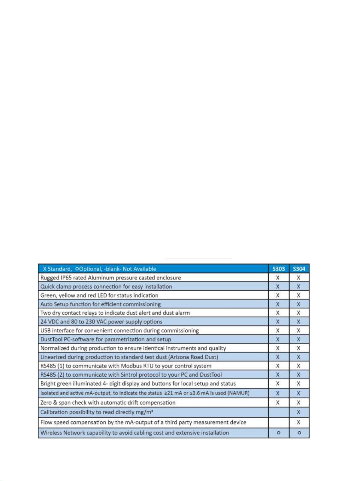
According to the chosen Accessories and options, S303 or S304 comes in the respective configuration.
Process Temperature (Deg. C)
(Standard) To be used in process temperatures below 200 Deg. C
(Option) To be used in process temperatures below 300 Deg. C
(Option) To be used in process temperatures below 700 Deg. C
Process Pressure (bar)
(Standard) To be used in process pressure below 3 bar, (Option) Pressure below 6 bar
Supply Voltages
24VDC +-10%, Minimum 10W output power per S201 or S203 which is connected to the power supply,
Low output ripple, max 1% V p-p of output voltage
Or 80 - 240 VAC, 47 –63 Hz
Air purge
(Standard) Without air purge. To be used in dry dust applications where dust build up and bridging is
not an issue.
(Option) With air purge to be used in adhesive or conductive dust applications where dust build up
and bridging may distort the measurement signal
Probe length (mm)
If the probe length is in comparison to the duct size very short, the measurement may be not representative.
For explanation: In vertical ducts dust particle will center with increasing flow speeds towards the middle of
the duct. In horizontal ducts large particles will concentrate on low flow speeds on the lower part of the duct.
In order to capture this effect Sintrol recommends to use:
For indicative measurements like for broken bag detection after dry filters a minimum probe length of
one quarter (1/4) of the duct size.
For more demanding and critical measurements in different flow speeds a probe size of a minimum
one third (1/3) of the duct size.
The probe shall not touch the opposing side of the duct. This would distort the
measurement
Probe Coating
(Standard) No coating
(Option) Teflon coating for wet processes under 250°C in non-hazardous areas
(Option) Diamond coating for abrasive and dry processes
(Option) Salocote coating for wet processes up to 700°C
Process Connection
(Standard) Quick Clamp, (Option) Flange
Other Options
RS485-to-USB converter
Wireless communication option
Network routers, wireless network routers and DustLog 8 reporting software. These supplies have
their own manuals which need to be read and followed.
Page 12 | 45
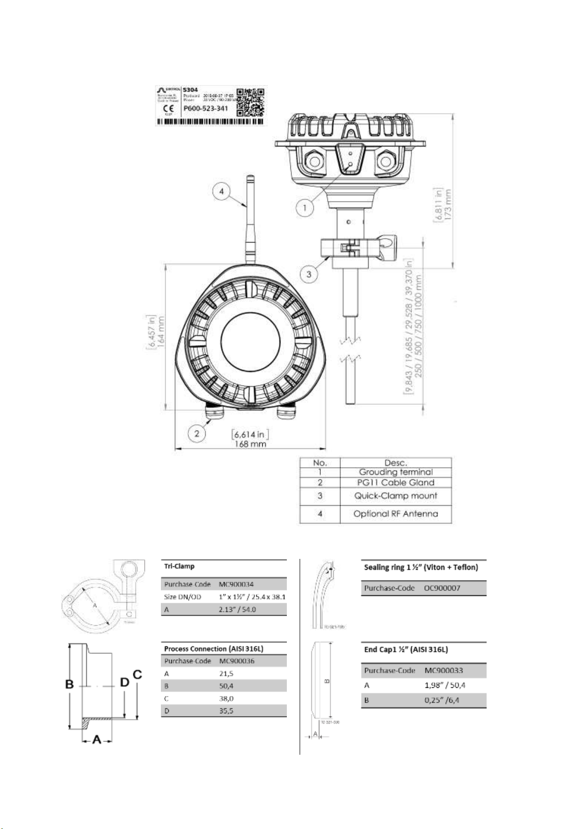
4.3 Illustrations of components and dimensions
Process connection components

Page 13 | 45
5Principle of operation, physical effects, and limitations
Sintrol dust monitors are based on a unique Inductive
Electrification technology. The measurement is based on
particles interacting with an isolated probe mounted into the
duct or stack. When moving particles pass nearby or hit the
probe a signal is induced. This signal is then processed through a
series of Sintrol’s advanced algorithms to filter out the noise and
provide the most accurate dust measurement output.
Classic triboelectric technology is based on the DC signal, which is
caused by particles making contact with the sensor to transfer
charges. Compared to DC based measurements, the Inductive
Electrification technology is more sensitive and minimizes the
influence of sensor contamination, temperature drift and velocity
changes. By using the Inductive Electrification
Technology it is possible to reach a detection limit as low
as 0.01 mg/m3.
According to its position in the Triboelectric Table each material transfers a specific charge to the probe.
Inorganic, electro-conductive materials (metals) create the lowest signals, Inorganic dielectric materials
(cement, minerals) generate average signals, Organic dielectric materials (wood, flour) generate the highest
Signals. This charge is captured by our sensor and its signal level is proportional to the particle concentration.
As a unit for this signal level the Inductive Electrification Unit (IEU) is used.
The relation between Inductive Electrification Unit (IEU) and the mA output signal can be established by
performing the Auto Setup function.
The relation between Inductive Electrification Unit (IEU) and the dust concentration in mg/m3can be done by
calibrating the signal to a reference method e.g. to the results of a gravimetric sampling series.
5.1 Influence of particle material
The signals transmitted by different types of dust particles vary greatly from one material to the other. For
example:
Inorganic electro-conductive materials (metals) create the lowest signals.
Inorganic dielectric materials (cement, minerals) generate average signals.
Organic dielectric materials (wood, flour) generate the highest signals.
This means that at the same concentration, different types of dusts generate different output signals. This
behavior can be compared to the behavior of opacity monitors, which show a different result depending on
the color of the material: at the same concentration, black dust will show less opacity than white dust.
5.2 Particle size
In terms of particle size, 425µm (40 mesh) is generally defined as the limiting size to classify a material as a
“dust.”
The minimum particle size which the S303 or S304 is able to detect is 0.3 µm.
The best working range of the S303 or S304 is between 1 and 200 µm.
Figure 1: Inductive Electrification Technology

Page 14 | 45
5.3 Linearity, maximum concentrations, and calibration
The measuring range and the behavior of the S303 and S304 depends on many factors, such as the dust
material, particle size, flow speed and installation location.
As an indication and averaging of different internal and external tests, Sintrol Products with Inductive
Electrification Technology show the following behavior over the measuring range:
Detection limit: 0.01 mg/m3
Linear range: from detection limit to several hundred mg/m3
Nonlinear rang: from linear phase up to several g/m3
Saturation: after nonlinear range
Figure 2: Illustration of uncalibrated measuring behavior
To measure higher concentrations than 200 mg/m3it is critical to have a linear
behaviour we recommend to perform reference measurements at the desired
concentration and add additional calibration points by using Sintrol
DustTool/calibration.
5.4 Influence of relative humidity RH %, condensation, and droplets in the measurement gas
Due to the working principle of the S300 Series, the variation of relative humidity in the measurement gas only
has an insignificant effect on measurements as long as there is no condensation.
Should there be condensate in the gas, these droplets will be detected as dust particles and distort the
measurement signal. No signal or a wrong (most likely too high) signal will be the consequence.
Make sure that the S303 or S304 is installed only in non-condensing conditions to mitigate the
effect of droplets affecting the measurement.
5.5 Influence of ambient temperature
Internal and external tests have shown that ambient temperature has very little effect on Sintrol’s products
using Inductive Electrification Technology.
Figure 3: Effect of Ambient Temperature

Page 15 | 45
5.6 Influence of flow velocity
As an indication and averaging of different internal and external tests Sintrol Instruments with Inductive
Electrification Technology show the uncompensated Influence of flow velocity as follows:
Figure 4 Influence of Flow velocity
On the S304 you have the possibility to connect the mA output signal of flow meter. This signal is used by the
S304 for compensation. The influence of flow velocity is then as follows:
The flow behaviour may vary depending on the dust material, the particle size, the
temperature and the installation location.
The minimum flow velocity is recommended to be 3m/s
Maximum tested flow velocity is 40m/s
5.7 Special dusts
Sintrol Products with Inductive Electrification Technology react properly to almost all dust materials.
The only known exception is heavy metal dusts where the behavior is known to be challenging. For measuring
such dusts, the S303 or S304 needs to be specially tested beforehand.
Page 16 | 45
6Mechanical Installation
Poisonous and hot gas hazard
When installing or removing the equipment, poisonous and hot gas may
be released from the duct to the atmosphere.
All applicable local and plant specific safety codes need to be studied and followed before loosening
any flange or create any other opening to the duct
Wear appropriate protective clothing, such as gas masks, gloves and follow any other additional
safety measure stated in the local, plant specific code.
Risk of burns due to hot components
When installing or removing the equipment, the S305 and other
connected components may be hot..
Wear appropriate heat protective gloves and follow any other additional safety measure stated in
the local, plant specific code.
Install the S303 or S304 by using the Weld-on process connection socket, with a Quick Clamp connection in the
desired location.
For installations with the RF version, make sure that all the S303 and S304 are oriented in the same direction
(antenna pointing in the same direction, vertical or horizontal) in order to avoid polarization losses in the
wireless communication.
Any information given or implied by Sintrol in any way regarding installation points, the
overall functionality of the system, or compatibility for a specific application are only
suggestive and do not replace careful functionality checks and if necessary approval by an
expert consultant.
6.1 Selecting the installation location
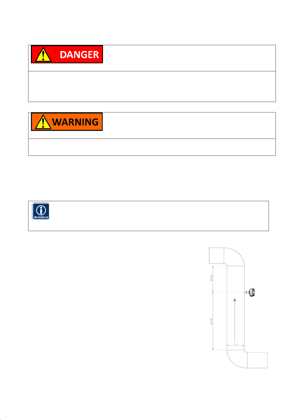
The best location for installation is in a section of duct where the particulate
has an even distribution and the flow is as laminar as possible. This is to
ensure that the sensor rod comes into contact with a representative flow of
particles. The ideal position would be in a section of duct that has no bends,
valves, dampers or other obstructions for a distance equal to at least three
duct diameters downstream or upstream (preferable 5 x duct diameter).
In some applications, a compromise must be made and the sensor will have to
be fitted in a position that satisfies the majority of above requirements. The
S201 or S203 must be attached to conducive ductwork so that the device will
be electrically shielded from interference and has good ground reference.
If installed downstream an electrostatic precipitator (ESP), the distance from
the ESP should be at least 20 m.
Although the sensor (lengths less than 1m) is not affected by vibration, very
high vibration levels should be avoided.
Figure 5 Recommended distance to duct bends (D = Duct diameter)

Page 17 | 45
Installation in a square duct
Figure 6 Installation in a squared duct
Installation in a round duct
Figure 7 Installation in a round duct
The sensor must not contact the opposite wall or any other obstacle inside the duct.
The only allowed interaction with the sensor are dust particles.
The unit shall be installed in a position, where the gas flow passes the sensor rod at a
90angle.
Although the sensor is not affected by vibration, very high vibration levels should be
avoided.
If possible the unit shall be installed in a position where the duct pressure is negative.
If installed downstream an electrostatic precipitator (ESP), the distance from the ESP
should be at least 40 m.
In case of occasional condensation conditions (droplets in the gas) it is recommended
to install the sensor rod showing approximately 5 Deg. downward to avoid liquids
cumulating at the S201 or S203 insulation.
6.2 Installing the sensor
Once the location of the unit has been selected, the mounting socket must
be welded to the pipe or duct. To do this, first cut a hole in the duct
slightly larger than the OD of the mounting socket, 35 mm. The socket
must be perpendicular to the flow in the duct. Make sure the socket is in
the right position and make an airtight welding
After welding the socket in position, insert the sensor.
The diameter of the hole must be minimum 35mm
Figure 8 Wrong socket installation

Page 18 | 45
7Electrical Installation and Wiring
Pay attention when choosing the cable. It must meet and be installed according to all locally
applicable codes, and must be suitable for the environment it is going to be installed in.
Always use a shielded cable when possible. Make sure to connect the shield to a protective
earth potential at a single location.
Use a minimum of 0,3 mm2 or AWG 22 conductor size.
When connecting the cabling make sure to leave enough slack to allow for the device to be
removed from the process for cleaning without disconnecting the cables form the dust
monitor.
Risk of electric shock!
A faulty electrical installation, excessive line voltage, or incorrect
operation may result in an electric shock.
Always turn off and unplug the S303 or S304 when you are not using it, when you intend to clean it,
or in the event of a malfunction.
Only connect the S303 or S304 if the line voltage of the socket corresponds to the data on the rating
plate.
Stand on an insulating pad and make it a habit to only use one hand when checking components.
Always work with another person in case an emergency should occur.
Disconnect power before checking the S303 or S304 or performing maintenance.
Make sure all equipment is properly grounded.
Always wear safety glasses when working on the power supply.
Read and understand User Manual before installation.
7.1 Grounding and usage of grounded power supply
Risk of injury!
If the S303 or S304 is not properly grounded, it may show false results, in
the worst case resulting in severe health impacts to workers and/or a
failure of the explosion prevention system.
Connect the external grounding, located between the cable glands to a stable local ground
potential.
The recommended grounding is where the S303 or S304 external grounding terminal is connected
to a nearby grounding strip or the properly grounded ductwork.
Make also sure that the power supply used to power the S303 or S304 is a Class 2 or equivalent
power supply.
Signs of improper grounding are:
Base values of over 3000 IEU (see Graph at DustTool) when the process is not running
The S303, S304 should show a clear reaction when touching the probe
The S303, S304 should show no reaction when touching the enclosure
Note that sub-par quality power sources might also induce such effects.
Page 19 | 45
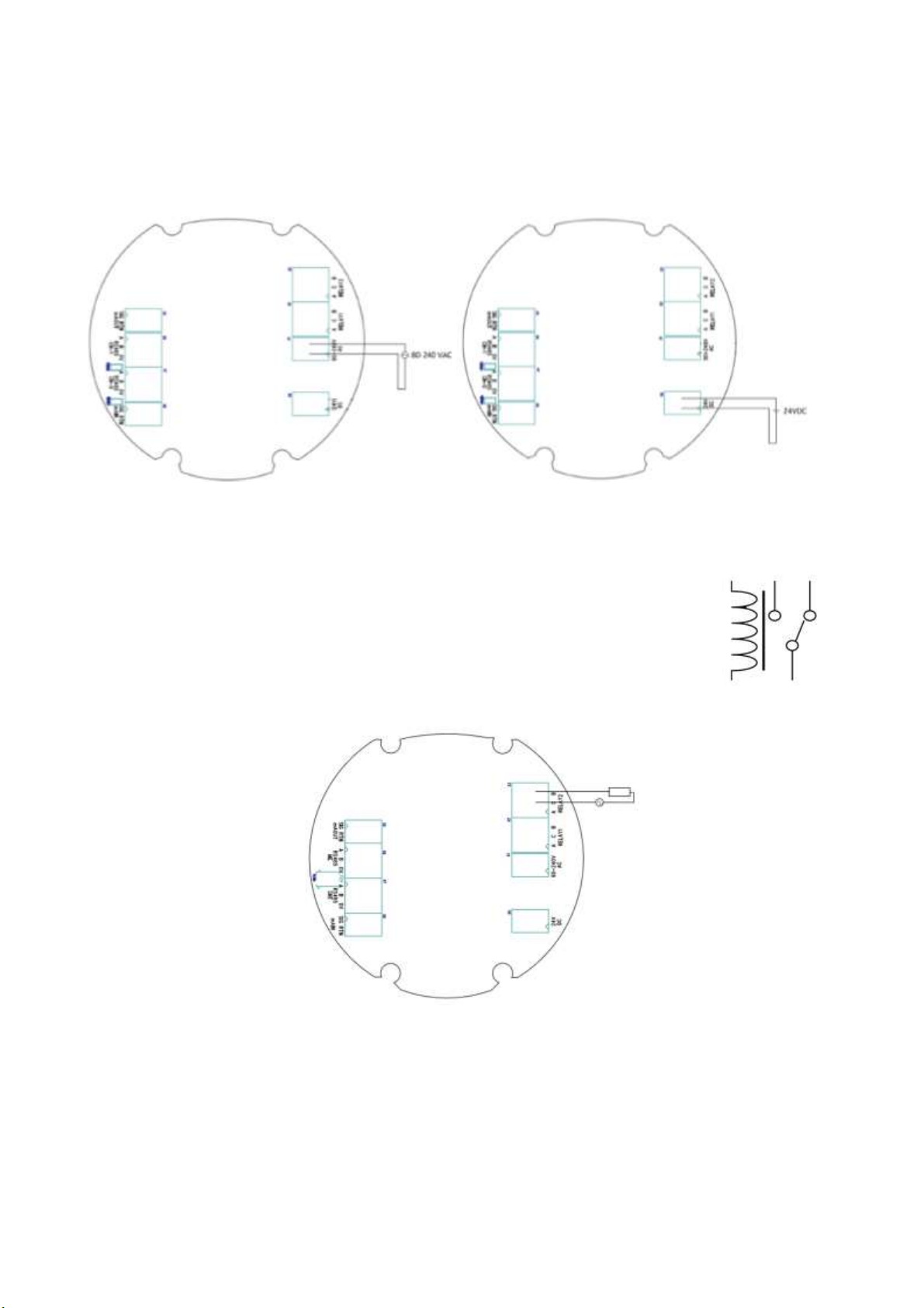
7.2 Connecting the voltage supply
The device can be connected to either a 24VDC voltage power supply or to a 80-240 VAC power supply. Make
sure to connect only one power supply. The polarity is irrelevant with both AC and DC power inputs.
Either 80-240 VAC or 24 VDC
Figure 9 Connecting 80-240 VAC Figure 10 Connecting 24 VDC
7.3 Connecting Relays
S300 Series devices are equipped with two dry-contact SPDT (Single Pole Double
Throw) relays. The contacts are labelled as A and B, and the common contact as C.
The relays can be used to power external loads up to 240VAC/5A.
Figure 11 Connecting Relays

Page 20 | 45
7.4 Connecting via USB
Direct USB connection on products makes it easy to connect to Sintrol Products without any additional
equipment, provided that the USB-port has the capability to provide enough energy. The USB port is a Micro
USB type B, located on the bottom-right corner of the main board inside the enclosure.
USB is intended to be used for easy parameterization of Sintrol products with dedicated
complementary DustTool software. However, the USB is not suitable to operate or
substitute a dedicated industrial bus and it is not intended for extended use in an industrial
environment during normal operation.
7.5 Connecting the mA-output
An active and isolated mA-output signal (mA+ and mA-) is used to transfer an analog 4-20 mA current signal
that describes the measurement value.
After the default auto-setup procedure, the normal signal level is set to be 5% of the scale (i.e. 4.8 mA). Thus a
max signal level of 20 mA indicates a 20-fold increase in dust levels since auto-setup. The scale of mA-output
can also be customized according to the end user application.
An mA-output loop is intended to be used as a long range analog data transfer in industrial environments. The
signal output is isolated to shield against local potential differences between the two end locations.
The device will also alarm on the mA output for device failures according to NAMUR NE 43.
mA output
State
4…20 mA
Normal measurement or Span/Zero self-test (relays indicating maintenance mode)
Over 24 mA
Failure, measurement grounded or device failure. Clean probe as instructed in
Maintenance –section.
Figure 12 mA loop connection
Other manuals for S300 Series
1
This manual suits for next models
2
Table of contents
Other Sintrol Measuring Instrument manuals


