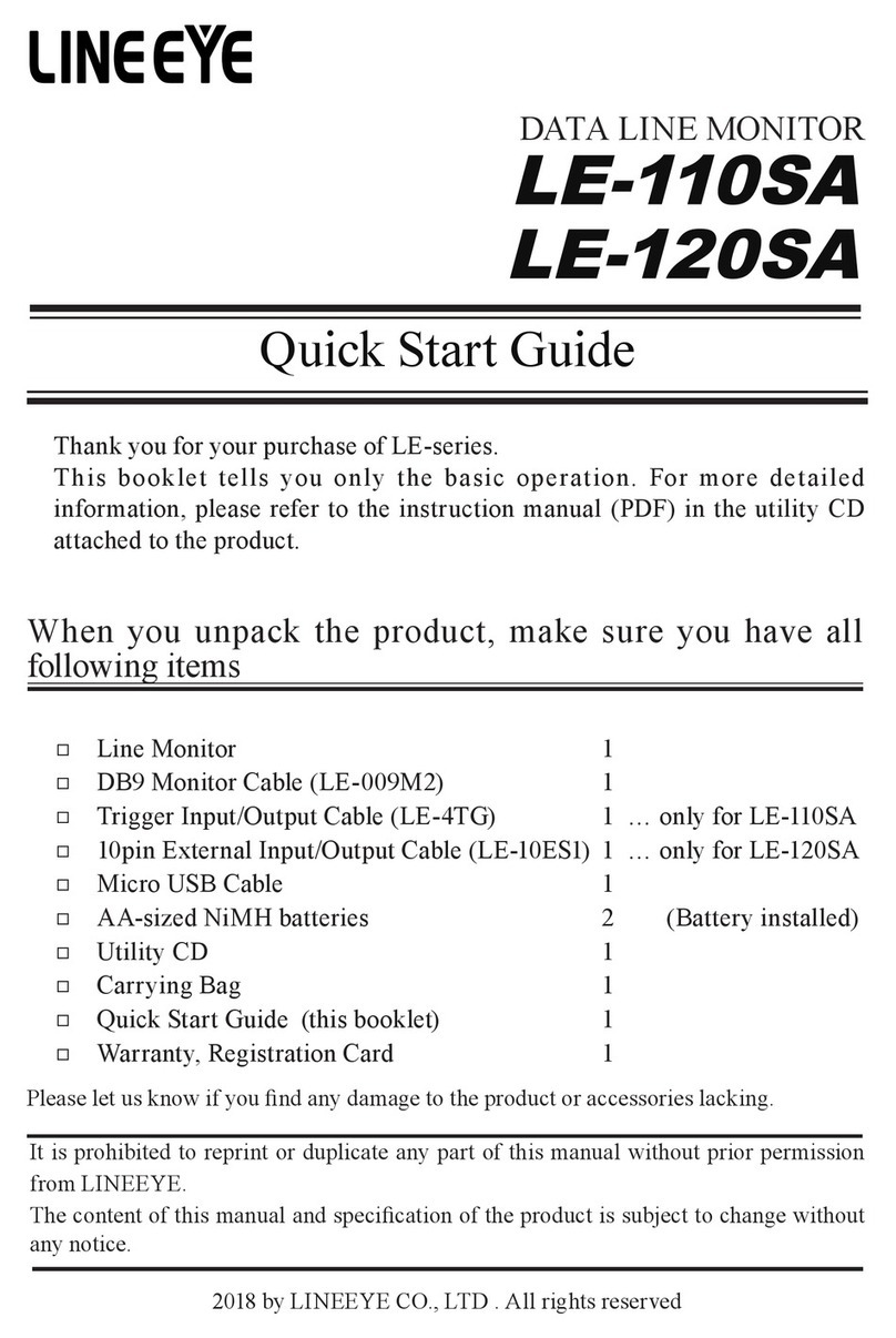
LineEye LE-1500R User manual

---Note---
The Nickel-Hydrogen battery is built into the product. It is not full charged to keep
the quality. Before using the product, charge the battery rst. If you dispose the
product, follow the regulations of your city.
COMPACT PROTOCOL ANALYZER
LE-1500R
Quick Start Guide
When you unpack the product, make sure of the following.
AC Adapter: 1
RS-232C Monitor Cable : 1
USB Cable: 1
Utility CD: 1
Carrying Bag: 1
Quick Start Guide (this booklet): 1
Registration Card, Warranty: 1
Please let us know if you find any damage to the product or accessories
lacking.Save the outside package and contact LINEEYE or LINEEYE
distributors.
The utility CD attached to the product contains the instruction manual.
Refer to the instruction manual for more detailed operation and important notes.
Ver. 1

Read this rst
Thank you for your purchase of LE-series.
To use it correctly, you are advised to read and understand this booklet and the instruction
manual stored in the CD thoroughly.
When you encounter some problems, you will nd helpful information.
Please do not use the analyzer in the following conditions.
[Description of the symbol and mark]
If the device is used without followings, there is a possibility of accidents, such as a
death or a serious injury.
If the device is used without followings, there is a possibility of accidents, such as a
injury, or material damage.
Warning
Do not use the AC adapter or battery excepting the one LINEEYE designated.This
may cause of exothermic reaction, ignition, electric shock, and malfunction.
Do not disassemble, modify or repair analyzer.This may result in a injury, electric shock,
and ignition.
Turn off the power and unplug the analyzer immediately when smoke or smells emanated.
Continuous use may result in an electric shock, burn and ignition.
Do not use the analyzer where there is inflammable gas. This may result in fire and
explosion.
Turn off the power and unplug the analyzer immediately when a liquid or foreign
substance get into the analyzer.Continuous use may result in ignition, electric shock and
malfunction.
Do not get the analyzer wet in water. This may cause of electric shock and malfunction.
Do not put the analyzer in re or place near the heater. This may result in a injury, re and
explosion.
Never plug or unplug the AC adapter in wet hands. This may result in an electric shock.
Do not touch the AC adapter or cables when out-breaking the thunder. This may result in
an electric shock.
Do not extend the plug to multi-outlets. This may result in the ignition.
Remove the dust from the AC adapter to avoid the ignition.
Caution
Do not give impact to the analyzer, such as dropping and hitting.
When removing/connecting the cable, hold the connector of the cable.
When plugging/unplugging the AC adapter, hold the body of the AC adapter.
Do not place the analyzer where is not at, or vibrated place.
Do not place the analyzer where temperature or humidity is above the specication or
sudden temperature change.
Do not place the analyzer affected by direct sun or near the re.
Do not place the analyzer in the strong magnetic eld, or static electricity place.
Do not place the analyzer where there is leaking water or electricity.
Caution
Warning
2
---- Contents ----
Read this rst ������������������������� 1
Nomenclature ������������������������� 3
Charging the Battery ���������������������� 5
Turn on the Power, Software Reset���������������� 5
Connect to the Target Devices������������������ 6
Interface Setting ������������������������ 7
Measurement Function ��������������������� 7
Condition Setting ����������������������� 8
Communication Condition�������������������� 9
On-line Monitor Function ������������������� 10
Simulation Function ��������������������� 11
Bit Error Rate Test Function ������������������ 12
Useful Functions ����������������������� 13
Trigger Function ������������������������ 13
Timing Waveform Measurement ����������������� 14
Auto Start/Stop Function��������������������� 15
File Management (Save/Load to a USB ash or SD Card) ����� 15
Auto Saving to a USB ash or SD Card �������������� 16
Usage on PC �������������������������� 16
Troubleshooting ����������������������� 18
User Registration ���������������������� 18

3
Nomenclature
General
⑫
⑬
①⑤
⑥⑦⑧
②
⑯
⑮
⑭ ⑪
⑨
⑩
③
④
Name Function
①AC Adapter Plug Connects the AC adapter.(It deals with the polarity of plus and
negative.)
②Power Switch Turns the power on/off.
③SD Card Slot The inlet for a SD card
④USB Host Port To connect to a USB ash memory
⑤Interface Sub-Board A sub-board equipped with RS-232C, RS- 422/485, and TTL
interface
⑥RS-232C Port Measurement port for RS-232C (V.24)
⑦TTL/ External Signal I/O terminal Measurement port for TTL. A port for external signal I/O
⑧RS-422/485 Port Measurement port for RS-422/485
⑨AUX(RS-232C) Port Used to input or output external equipment equipped with RS-
232C interface.
⑩USB Device Port Uses for a remote-control from a PC, or for updating rmware.
⑪Liquid Crystal Display Wide view angle and high contrast liquid crystal display.
⑫Line State LED Indicates logical status of signal line on the target interface.
⑬Action State LED Indicates the status of an analyzer's operation.
⑭Keypad Press to enter commands and data.
⑮Battery Cover Open only when replacing the nickel-hydrogen battery.
⑯Contrast Adjust Knob Adjusts the display contrast.

3
4
Key Function
[ RUN ] Starts monitoring, measuring or testing operation.
[ STOP ] Stops monitoring, measuring or testing operation. Interrupts printing.
[ MENU ] Returns to the top menu for selecting functions and setting conditions.
*Returns to the previous screen.
[ DISPLAY MODE ] Displays the monitored or measured data. Switches over to the display
format.
[ TIME/COUNT ] Switches to counter/timer display and timing waveform display.
[ LOAD/SAVE ] Sets conguration of le management for the storage device
[ FIND ] Switches over to the retrieval function.
[ PRINT ] Switches over to the printing function.
[ HEX/CHAR ] Switches over the monitored data displayed in char. to one in hexadecimal.
[ ZOOM/CODE ] Zooms up in the timing waveform screen. Changes the display code of
monitored data.
[ PAGE UP ] Goes to previous data. Moves the setting items upward.
[ PAGE DOWN ] Goes to next data. Moves the setting items downward.
[ ] , [ ] Scrolls the data line.Moves the cursor on the condition setting screen.
[
] ,
[
]Scrolls the displayed data character by character.Changes or selects the
setting item on the condition setting screen.
[ ENTER ] Denite input for execution of function or a command.Pauses the display
when pressing the key during the measurement.
[ 0 ] ~ [ F ] Enters the corresponding numerical values.Selects an item number or the
data to be sent.
[ TOP/DEL ] Displays the top section of data. Deletes the entry indicated by the cursor.
[ END/X ] Jumps to the end of the screen. Enters data “Don’t Care.”
[ SHIFT ] Press to use the expanded alternate function of each key.
[ SHIFT ] + [ PRINT ] Prints the hard copy (screen image).
[ SHIFT ] + [ FIND ] Sets conguration of retrieval condition.
[ SHIFT ] + [ PAGE UP ] Moves to the setting help screen upward.
[ SHIFT ] + [ PAGE DOWN ] Moves to the setting help screen downward.
[ SHIFT ] + [ DISPLAY MODE ] Turns on/off the back-light. (Applicable models only)
[ SHIFT ] + [ HEX/CHAR ] Selects the xed transmission data.
*This booklet uses [+] mark, when two keys needs to be pressed at the same time.
(e.g., [ SHIFT ] + [ PRINT ])

5
Charging the Battery
The Nickel-Hydrogen is fully charged in about 2.5 hours by the AC adapter.
Please charge the battery before using the product.
* The "BT" LED blinks in green when charging, and lights in green when completing the
charge.
* The analyzer can perform the battery drive for about 6.5 ~8 hours with the full charge.
[Note]
Do not use the AC adapter or battery excepting the one LINEEYE designated.
If you are not going to use the analyzer for a long term, ll up the battery before putting back.
After that, try to charge the battery every 6 months.
If the service time after charging becomes extremely short, the battery must be replaced with a new
one. (Battery model: P-19S)
* Even though the service time becomes short within the warranty period, you need to
purchase the new one because batteries are considered as consumable part.
Lithium Battery
The data of memory IC and timer IC is saved for about 10 years by built-in Lithium battery
even if the power supply is OFF.
Turn on the Power, Software Reset
Turn on the power of analyzer (Press left side
button.)
The opening screen with rmware version will be
displayed after the self-check test.
* If "Self-check NG" is displayed, please contact LINEEYE distributors or LINEEYE directly.
* The latest rmware is available from LINEEYE web page.
Software Reset
To restore the initial conditions (factory setting) into the analyzer, turn on the power while
pressing [Enter]+[Top/Del] keys. [Initialized!] will be displayed in the opening screen.
Calibration
Enable to have a diagnostics by the analyzer itself.
* After the calibration, it will go back to the initial conditions and capture memory will be
erased.
Preparation Remove all cables from the analyzer and insert a USB ash or an optional SD
card to the memory card. (if you have one)
Operation Turn on the power while pressing [1]+[D]. Press all keys one by one when the key
marks
are displayed. "--OK--" will be displayed if the result is ne. Turn off
the power of analyzer.
* If "NG" is displayed, please contact LINEEYE distributors or LINEEYE directly.

5
6
Connect to the Target Devices
Connect to RS-232C
To monitor the communication data
Connect the monitor cable (LE-25M1) to the Dsub
25pin connector of RS-232C for the target devices.
To have the transmission/reception (simulation) test
Set the interface condition according to the DTE/DCE
specification and pin assignment of RS-232C cable
for the target devices. (->P7)
Connect to RS-422/RS-485
To monitor RS-422 To simulate RS-422
Device ADevice BRS-530 port
( ) = Pin number
TXD+ RXD+
(14 )
TXD-RXD-
( 2 )
RXD+ TXD+
(16 )
RXD-TXD-
(3 )
SG SG
(7)
Device RS-530 port
( ) = Pin number
TXD+ (16 )
TXD-( 3 )
RXD+ ( 14 )
RXD-(2 )
SG ( 7 )
To monitor/simulate RS-485
Device ADeviceBRS-530 port DeviceC
( ) = Pin number
TX/RX+ TX/RX+ (14 ) TX/RX+
TX/RX-TX/RX-(2) TX/RX-
SG SG (7) SG
RS-422/RS485Port
Connect to TTL
When you measure UART of TTL, I2C, or SPI set the “PORT” item of “INTERFACE” setting to
“TTL” and connect the analyzer with the target by dedicated cable.
■When you execute monitoring or send/receive simulation of TTL level line
Either is Dsub 25 pin
connector
MONITOR Cable(LE-25M1)
RS-232C Port
Dsub25
Dsub25
Lead wire Signal name Denition
Brown TXD Monitor input / Simulation output of SD data.
Red RXD Monitor input of RD data.
Orange RTS Monitor input / Simulation output of RTS control line.
Yellow CTS Monitor input of CTS control line.
Green GND Signal Ground

7
Interface Setting
Select the measurement port which is used in the target device.
Press [1] on the top menu screen([MENU]), and select “INTERFACE.”
PORT (Selecting Ports to Measure)
■
Select "RS232C" to measure RS-232C, "RS485" to measure RS-422/485, "TTL" to
measure TTL interface.
The action LED light of RS-232C and Others will be switched.
MODE (DTE/DCE Switch)
■
Select the specification of signal input/output for the measurement port while using
Simulation or BERT function. Select "DCE" if the target device is "DTE". Select "DTE" if the
target device is "DCE".
“DTE” is widely used in PC and data terminal devices. “DCE” is widely used in modems and termi-
nal adapters etc.
LED lighting for SIM DTE and SIM DCE is switched when using the Simulation or BERT function.
When monitoring is executed, setting this is not necessary.
Only during[RUN], signal of measurement port will be the output pin when using Simulation or
BERT function.
POLARITY (Polarity Switch)
■
Normally select “NORMAL”.
In INVERT, all the signal polarity of SD and RD including the idle state of the line is inverted.
DRVCTRL (RS-485 driver control)
■
Setting of the driver IC control method when selecting "RS-485"
LINECTRL (Control of the control line)
■
Control setting of the control line when selecting "RS-232C"
LEVEL (signal voltage level selection)
■
Selection of the signal voltage level of the measurement target when selecting “TTL”. Select
from 5.0V, 3.3V, 2.5V, or 1.8V depending on the specication of the target hardware.
OUTPUT (Output selection)
■
Output selection of the simulation when "TTL" is selected. Select from "PUP" (open
collector output with pull-up resister), “NO-PUP” (open collector output without pull-up
resister),, or "CMOS" (CMOS push pull output) depending on the hardware specication of
the target device.
Measurement Function
Press [MENU](top menu) and move "
" mark to select the appropriate function.

7
8
ONLINE Function Monitor communication data at real time (->P10)
DELAY Function Measure the delay time of the signal changes and voltage of RS-232C/TTL.
BERT Function Measure the transmission quality of communication line. (->P12)
MANUAL Function Have the transmission/reception test by key operation. (->P11)
FLOW Function Have the ow control on Simulation function.
ECHO Function Echo back function
*Refer to the instruction manual stored in the CD to use the Delay, Flow and Echo functions.
Condition Setting
Set the environmental conditions required to operate
the analyzer.
Press [MENU](top menu) ->[3]"CONDITION" to
select the conditions.
No. Item Setting Conditions
0 BUFFER SELECT
Sets the allocation of partitions in the capture buffer to store the
measured data.
Selects ON/OFF for the protection of the capture buffer, buffer full
stop function, automatic back up function, AUTO SAVE function,
and automatic saving le. Selection of save device.
1RECORD &
DISPLAYCONTROL
Selects and sets ON/OFF for each display; idle time, time stamp,
line status.
Selects BSC translation.
2 PRINT OUT CONDITION Sets printing conditions and selects an output port.
3 REMOTE CONDITION Sets the AUX communication conditions. Wi-Fi setting.
4 AUTO RUN
Sets ON/OFF of the automatic start/ stop. Sets the starting/ending
time and
ON/OFF of the automatic RUN.
5 TIME & DATE SET Sets time and date (Sets the built-in clock).
6 OTHER FUNCTION
ON/OFF of the key click sound, time until automatically turning OFF
the back-light, ON/OFF of the [RUN] operation check display, ON/
OFF of prohibition of measurement at the time of battery warning,
ON/OFF of prohibition of simulation.
Press a number key corresponding to each item to set the conguration (or move[ ▲ ] [ ▼ ]
and then press [ENTER].)
For example, press [5] to set the time and date.
1: Current time and date is displayed in the rst line.
2: Move the cursor to change the setting.
3: Input using [0] [9] keys.
4: Input the date information of year (last 2 digits), month and day.
Input the time information by H/D/S (24hours)
5: Press [Enter] to reect the setting.
* To cancel inputting, press [Menu] key. (Not [ENTER] key)

9
Communication Condition
Press [MENU] -> [0] "Conguration" to set the communication conditions.
Move " "mark by pressing [ ▼ ],[ ▲ ],[PAGE DOWN],[PAGE UP] keys or press [0] - [F] keys
to set the conguration.
Press [PAGE DOWN]
Press [PAGE DOWN]
PROTOCOL
Select ASYNC for Asynchronous communication.
S-SPEED (Sets the transmission communication speed.)
R-SPEED (Sets the reception communication speed.)
When "S-SPEED" is set, "R-SPEED" is automatically set.
Press [F] to set any communication speed by 4 effective
digits.
For example, to set speed of 123.4Kbps, Input [1] , [2] , [3] ,
[C](.) , [4] , [D](k)
CODE (Sets the display code on the screen.)
CHAR BIT (Sets a character bit length.)
PARITY (Sets parity bit)
"MP" is used for communication adding Multi-processor bit.
STOP BIT (Sets a stop bit length)
It is valid only for Simulation function.
For receiving data, 1 bit is set in spite of any setting.
BCC (Sets block check code)
When “OFF” is set, block check is not executed.
BGN CHAR (Sets a calculation start character for BCC)
END CHAR (Sets a calculation end character for BCC)
ITB CHAR (Sets an ITB character)
Not need to set for normal use.
TRANSPRT
Set "OFF" for normal use. Set "ON" to measure in
Transparent mode.
DLE CHAR (Sets a DLE character for transparent mode)
Not need to set for normal use.
SEQUENCE (Sets bit sequence)
Set "LSB" rst for ASYNC communication.
FRM TIME (Sets a non-communication time considered to
be a frame end)
When the time reached to the setting, it ends the frame.
FRM END (Sets the frame end characters)
When receiving the frame end characters, it ends the frame.
The left screen shows the setting of carriage return (0Dh).

9
10
On-line Monitor Function
This function records communication data in the capture buffer without affecting the
communication.
Also, it displays clearly following each communications protocol.
Operation
Press [MENU](top menu) and select“ONLINE".
Press [0] to set the conguration. (->P9)
Press [Menu]->[3]->[1] to set the time stamp, idle line, line
state, and BSC translation.
Set other conguration if necessary.(->P8)
Press [RUN] to start measuring, and the RUN LED will
light.
Then, the measured data will be displayed on the screen.
SD data
RD data
[ENTER] The screen is temporarily paused. Press it
again to continue.
[STOP] Stop measuring.
Change the Display Mode
Press [Display Mode] to change the mode.
Data display → Line state display(*1) → Translation display(*2) → Display per the frame(*3)
*1: It is displayed if recording the line state.
*2: It is displayed if setting "On" on translation display.
*3: It is displayed if recording the time stamp.
Change the Display Code
Press [HEX] to change the display codes to HEX. To return to the former code, press it
again.
Pressing [ZOOM/CODE] changes the display code in following order.
ASCII → EBCDIC → EBCDIK → JIS7 → JIS8 → HEX
Baudot ← IPARS ← Transcode ← EBCD
Timer and Counter
Press [TIME/COUNT] to display the value of time and
counter.
"Timer0, 1" "Counter0, 1" is used when measuring
with trigger function. (->P13)
"Counter 2, 3" is used when counting the total number
of SD/RD data after starting the measurement.
Scroll, Jump, Search
Scroll the screen by pressing [PAGE UP],[PAGE DOWN] after the measurement.
Jump function Specify the position of measured data by [0]-[9]keys and press [Enter].
Search function Specify the search conditions by [SHIFT]+[FIND]keys and press [Find] (or "▲","▼")
or [Enter].

11
Simulation Function
With the simulation function, the analyzer acts as the counterpart to the target device and
performs transmission/ reception tests.
In this section, it only describes the MANUAL mode, which sends the data registered
in transmission table corresponds to the keys. To know about other modes, refer to the
instruction manual stored in the CD.
Operation
Press [MENU](top menu) and select "MANUAL".
Press [0] and set the communication condition. (->P9)
Press [Menu]->[9] and display the summary screen of data
tables.
There is "0" to "F" transmission data tables which
corresponds to the key board.
Select the table group (GROUP) and table number by [0]-[F]
key and press [ENTER].
Input data by [0]-[F] keys in HEX. To input data in alphabet,
press [SHIFT]+[HEX/CHAR].
Press [HEX/CHAR] to change the input data in HEX.
For more details of setting, such as BCC insertion ([SHIFT]+[ENTER]), Parity error
([SHIFT]+[E]), copy/paste and delete, refer to the instruction manual stored in the CD.
Press [MENU]->[A](Manual Factor), and set the
"DELAYTM" (Space between characters), "REPEAT"
(repetitive transmission), and "IDLETM" (Interval of repeat
transmission).
Press [RUN] and then [0]-[F] key corresponds to the transmission data table. The table group
to be transmitted can be changed by [SHIFT] + [
▲
] or [
▲
]. Transmission data and reception
data can been seen on the screen.
Press [SHIFT]+[0]-[D] key to send the pre-set data.
Press [SHIFT]+[E] or [F] to turn on/off the control line of RS(RTS)/CS(CTS) and ER(DTR)/
CD(DCD).
Press [STOP] to end the measurement.
(e.g.,) Send "ENG" at DCE mode (->P7). When receiving "TEST1CRLF", send "NG2CRLF" on
the table1 .
[RUN]
Data Table
Send “ENG(05h)” by pressing [SHIFT]+[0]. Send "NG2 CRLF"by pressing [1].
Receive "TEST1CRLF".

11
12
Bit Error Rate Test Function
With Bit Error Rate Test function, the analyzer evaluates the quality of a data communication
line of target devices (modems and converters etc.).
(e.g.,) Connection of Loop-back test
MO D E M
L INE
DIGITAL
PART
ANALOG
PART
DIGITAL
PART
ANALOG
PART
MO D E M
:LoopBackPoint.
The loop-back point can be usually set and changed by using the self-test function of
the modem. (Refer to the instruction manual of the modem.)
Operation
Press [MENU](top menu) and select "BERT".
Press [0] and set the communication condition. (->P9)
Press [MENU] and [8]"BERT" and set "Test Mode"(Test
t i m e , R e p e a t o p e r a t i o n) , " P a t t e r n " (t e s t p a t t e r n ),
FLOWCTRL" (On/Off of transmission control on RTS/CTS).
The left setting indicates that it repeats 511 random test
pattern for 10 minutes.
Press [RUN] to start transmitting test pattern and display
the result of reception data compared to the test pattern.
Press [STOP] to end the measurement. However, the transmission of test pattern continues
and RUN LED is still lighting. Press [MENU] to end transmitting the test pattern.
Name Description Measured Range
Savail Effective period after synchronization is rst
established. 0~9999999(sec)
R-Bit Number of received bits while synchronization
is maintained. 0~9999999~9.99E9
E-Bit Number of bit errors occurred. 0~9999999~9.99E9
Bit-ER Bit error rate. 0.00E-0~9.99E-9
LOSS Number of deviations from synchronization. 0~9999 2
R-Blk Number of received blocks while
synchronization is maintained. 0~9999999~9.99E9
E-Blk Number of blocks which included bit errors. 0~9999999~9.99E9
Blk-ER Block error rate. 0.00E-0~9.99E-9
E-Sec Time when bit errors were detected during
Savail 0~9999
%E.F. S Error-free seconds (%) 0.000~100.000(%)

13
Useful Functions
Trigger Function
Trigger Function is for starting a specic action upon occurrence of a specic event as the
trigger.For example, when receiving the specific data, it changes the external terminal or
counts the error times.
Press [MENU](top menu) ->[2]"Trigger".
Enable the trigger by pressing [SHIFT]+[0]-[3].
Set the trigger factor and action for each trigger by pressing
[0]-[7] keys (or [ENTER].)
To use the timer/counter in the trigger condition, press [F] for
detailed setting.
< ACTION >
STOP Stop measurement. Able to set with OFFSET
TRIG SW Enable other trigger conditions
TIMER Start/ Stop/ Restart
COUNTER Count/ Clear
BUZZER Buzz sound
SAVE Save data in memory card
SEND Send specic data on MANUAL simulation
OT2 Output low pulse for about 1ms to the external
trigger terminal OT2
< FACTOR >
ERROR Communications error (Parity,
MP, Framing, BCC, Break)
CHARACTER Max 8 characters with don't
care and bit mask
IDLE TIME Idle time more than specied
time
TM/CT Matched with timer/counter
value
LINE Status of signal line and
external trigger input
(e.g.,): Stop measurement when receiving "41h, 42h, 43H" on SD, and then "4Fh, 4Bh, 30h" or
"4Fh, 4Bh, 32h" on RD for 3 times.
Set the Counter0 to
be 3.
Enable the Trigger0/2
by pressing
[SHIFT]+[0] and
[SHIFT]+[2].
Condition of Trigger0
Input "41h, 42h, 43h"
on SD.
Action of Trigger0
Enable the Trigger1
condition.
Condition of Trigger1
Set "4Fh, 4Bh, WO"
on RD. Set "WO" by
pressing [SHIFT]+[0].
Action of Trigger1
Set "INCREMENT"
on the Counter0.
Condition of Trigger2
Select "TM/CT" and
Conter0.
Action of Trigger2
Stop measurement
immediately
("QUICK").

13
14
*External Trigger Input/Output
Signal name Pin name Input/Output
Power for external circuit(*1) PWR
External trigger output 2 (TTL level output)(*2) OT2 O
External trigger output 1 (TTL level output)(*2) OT1 O
External trigger input (TTL level input)(*3) IN I
Signal GND GND -
*1: Voltage () can be set in "LEVEL" item.
Maximum output current is 30mA.
*2: Open drain output, +5V, 10KΩ pullup
*3: Input voltage range is -0.5V - 6.0V.
It is pulled up with 10KΩ on +5V.
Timing Waveform Measurement
This function is to measure the timing of data as a logic analyzer through a communication
line.
[Press [MENU](top menu) ->[4](WAVE MONITOR) and set
"MONITOR:ON".Set the sampling clock (50ns-1ms) and
trigger position (of the memory).
Press [PAGE DOWN] and select the logical status of the
line to be the trigger condition.
Select the edge by pressing[SHIFT] + [0](↓) or [SHIFT] + [1]
(↑).
Press [RUN] and start measuring and record logical status of the lines at the specified
sampling clock in the memory.
When the trigger condition is satised and waveform measuring ends, "WAVE-MON END"
will be displayed on the right bottom of the screen.
Press [STOP] to end measuring and display the waveform
by pressing [Time/Count] key for a few times.
→ Normal Data Display → Timer/Counter → Timing Waveform
Scroll the screen by[
] /[ ] or [PAGE UP]/[PAGE DOWN] keys.
Enlarge or reduce the display by [ZOOM/CODE] or [SHIFT]+[ZOOM/CODE] keys.
It is possible to calculate the time between two points.
Press [2]or [SHIFT]+[ ] and [3] or [SHIFT]+[ ] to move
the cursor to position A, then press [ENTER].
Move the cursor to position B.
AB
Connector : 2.54mm pitch
pin header type

15
Auto Start/Stop Function
The AUTO RUN function enables to start and stop a measurement at the specied time.
It is useful when you monitor at the specic time only.
Press [MENU]->[3]->[4]("AUTO RUN").
Set Mode (repeat mode), RUN TIME (starting time), STOP
TIME (end time), P-ON RUN (Auto run when powering on).
In this setting, it starts measuring at 12:30 until 13:00 every day.
File Management (Save/Load to a USB ash or SD Card)
Measured data and conguration can be saved in a storage device such as USB
ash or SD card. And saved les can be edited from the analyzer and PC.
Press [LOAD/SAVE] to display the directory screen.
Select the appropriate le by [▼]/[▲] keys and press [1]-
>[ENTER] to load the le.
Or press [2]->[ENTER] to delete the le.
Press [0] to save data. Name the le by [0]-[F] keys and
press [ENTER].
"TYPE:DT" stands for the measured data and "TYPE:SU"
stands for the conguration data.
To save a partial data, select "RANGE:CURRENT" and
input the data size (in 1k byte).

15
16
Auto Saving to a USB ash or SD Card
Transfer the data on the captured memory into the optional USB ash or SD Card at specied
size automatically while measuring.
It is useful for rare network trouble of unknown case by recording communication data for a
long time.
Insert a USB ash or an optional SD card to the memory
card slot of analyzer.
Press [MENU]->[3]->[0] and then "Full Stop:OFF" and
"AUTO SAVE:ON".
Select the type of storage device from “DEVICE”
item.
*If setting "FULL STOP:ON", the measurement will be stopped when the capture buffer becomes full.
Press [PAGE DOWN] and set MAXFILES (Max saving
les), FILESIZE, APPEND (How to use the existing le
when saving new data).
*When setting the FILESIZE larger than the capture memory, captured data in the storage device cannot
be loaded to the analyzer.
In this case, use the PC link software (the light edition of LE-PC300R) in the attached CD-ROM (Refer to
the manual of the software for how to use) to use the data on PC.
Press [RUN] to start measuring and the log data in the capture memory is saved into the
storage device with the name of "#XXXXXXX.DT".
("XXXXXXX" is the number which starts from 0000000). When the number of the auto-saved
les is reached to the MAXFILE, the oldest le will be deleted and new le will be saved
If the storage device has the existing auto-saved les, warning
message will appear before starting the measurement. Press
[RUN] to continue, or [STOP] to save data into the HDD of PC or
another storage device.
* "APPEND:OFF" deletes the existing auto-saved les and starts saving from "#0000000.DT".
* "APPEND:ON" keeps the existing auto saved le and starts saving from the next number of existing le
name.However, if it reaches to the MAXFILES already, it will delete the oldest le before starting the
measurement.
Note
Do not turn of the power supply while using Auto Saving. It will affect not only the
autosaving le, but also the storage device itself.
Usage on PC
By using PC link software (Light Edition), you can execute real time measurement and convert a
captured le into text le. The Captured data is in unique data form thus you need to convert it to use
it on PC.

17
PC link software “LE-PC300R (Light Edition)”
With this software you can take the monitor data into PC through USB port, AUX port(serial),
Wi-Fi, or storage device.
* Wi-Fi is only available in Japan, USA, and Canada.
Install of PC link software
■
The Utility folder of attached CD-ROM includes the light edition of the PC link software “LE-
PC300R”.Double-click setup.exe in the folder and install it following the install wizard.
LE-PC300R (Light Edition) has 10 minutes limitation for measurement time. When you need to
measure for more long time please purchase the full edition of LE-PC300R.
For “how to use” of LE-PC300R (Light Edition), refer to the online help of LE-PC300R.
Text conversion
■
You can convert the data le which is measured by the analyzer into text le. By clicking
of LE-PC300R, the text conversion window opens. Then select the folder which has the
data to be converted and select the data. You can select normal format or translation
format for the text conversion. You can also convert it to csv format.
LE-PC300R (Light Edition) has 3 les limitation (at
one time) for the le conversion. When you need
to convert many les at one time, please purchase
the full edition of LE-PC300R.
Save
■
Click to save the data which was measured by LE-PC300R.
PC Connection
■
The Utility folder of attached CD-ROM includes
the light edition of LE-PC300R.
Double-click setup.exe in the folder and install it
following the install wizard.
When you use USB connection, you need to
install the USB driver before the use. The driver is
in the Driver folder of attached CD-ROM.
Start/Stop measurement
■
After nishing conguration of communication condition, click to display and record
the measured data. Click to stop measurement.

17
18
Troubleshooting
When you encounter some problems, please refer to "FAQ" from LINEEYE web page.
If you still cannot solve the problems, please contact LINEEYE or LINEEYE distributors.
Can monitor only transmission or reception line.
It is possible that you select Simulation function. Select Monitor function from top menu.
"B" is displayed on the screen without any communication data after pressing [RUN].
It is possible that you select "POLARITY:INVERT" at Interface setting. Press [MENU]->[1]
and select "POLARITY:NORMAL" .
Cannot send pre-registered data by pressing [SHIFT]+[9] when using MANUAL Simulation.
Press [MENU]->[1] and set "LINECTRL:OFF".
Press [MENU]->[1] and select "DRVCTRL:AUTO" if "PORT" is "RS530".
Find a small light on the LED of line state which is not in use.
Use the accessory cable. It is possible that the line standing next to it affects (crosstalk) and
lights the LED.This is not a product malfunction.
"ILLEGAL CARD" is displayed after inserting the SD card and pressing [LOAD/SAVE].
Use the LINEEYE optional SD card. Max capacity of SD card depends on the analyzer model.
LINEEYE does not warranty the SD card for other manufacture.
User Registration
For any technical questions, please feel free to send us an email or FAX.
We do answer your questions via phone but prefer email or FAX.
Email: info@lineeye.co.jp FAX:+81-75-693-0161
(ofce hours: 9:00to12:00, 13:00to18:00)
Please register your products before asking questions about your products.
You can register your products from LINEEYE web page. Go to [Support] and fill in the
application.
You can also register your product via FAX using the registration card attached to the
products.

LINEEYE CO., LTD.
4F., Marufuku Bldg., 39-1, Karahashi Nishihiragaki-cho,
Minami-ku, Kyoto, 601-8468, Japan
Phone : +81-75-693-0161 Fax : +81-75-693-0163
URL : http://www.lineeye.com
Printed in Japan
M-1715QE/LE
Table of contents
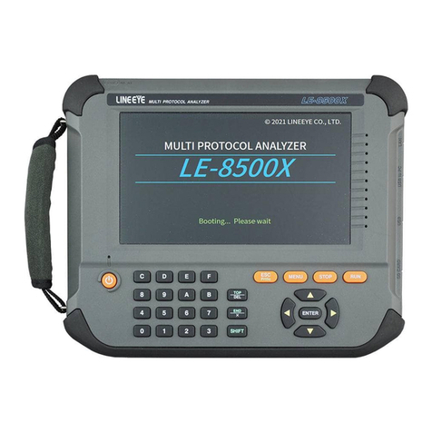
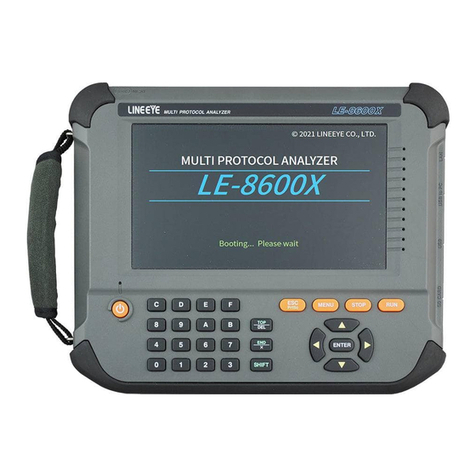
Other LineEye Measuring Instrument manuals

LineEye
LineEye LE Series User manual

LineEye
LineEye LE-580FX User manual

LineEye
LineEye LE-8500X-RT User manual

LineEye
LineEye LE-8500XR-RT User manual

LineEye
LineEye LE-8500X User manual

LineEye
LineEye LE-8600XR User manual

LineEye
LineEye LE-110SA User manual

LineEye
LineEye LE-650H2 User manual

LineEye
LineEye LE590-TAP User manual

LineEye
LineEye LE-3500XR User manual