TelcoBridges Tmedia TMG800 User manual

Installation Guide
800 Series Gateway Standalone &
800 Series Gateway 1+1
October 29, 2013

The information in this document as well as product specifications referred to throughout, are subject to change without notice.
No part of this document may be reproduced or transmitted in any form or by any means, electronic or mechanical, for any
purpose, without the express written permission of TelcoBridges. TelcoBridges may have patents or pending patent
applications, trademarks, copyrights, or other intellectual property rights covering subject matter in this document. The
furnishing of this document does not give you license to these patents, trademarks, copyrights, or other intellectual property
except as expressly provided in any written license agreement from TelcoBridges Inc.
The information provided in this document is intended as a guide only. For the latest detailed engineering specifications, please
contact TelcoBridges TB Support or visit the TBWiki: http://docs.telcobridges.com. TelcoBridges is committed to continually
improving product designs; as a result, product specifications may be subject to change without notification.
© 2003-2013 TelcoBridges. All rights reserved.
TelcoBridges, Tmedia, TMG800, TMG3200, TMG3200-RJ, TMG3200-TE, TMG3200-DS3, TMG3200-STM1, TMG7800,
TMG7800-TE, TMG7800-DS3, TMG7800-STM1, TMG7800-CTRL, TMG-CONTROL, TMG7800-TMS, Tsig, TSG800,
TSG3200, TSG3200-RJ, TSG3200-TE, TSG3200-DS3, TSG3200-STM1, Ttrans, TMGIP800, TMGIP3200, TMGIP7800,
Tmedia 1+1, Tmedia N+1, TMG800+1, TMG3200-TE+1, TMG3200-DS3+1, TMG3200-STM1+1, TMG7800-TE+1,
TMG7800-DS3+1, TMG7800-STM1+1, Tdev, TMP800, TMP6400, TMP6400-CTRL, TMP6400-TMS, Tmonitor, TM1000,
TM3000, Toopack, Toolpack API, TB640, TB-8, TB-16, and TB-Video, are trademarks of TelcoBridges Inc. All other
trademarks are the property of their owners. This information is subject to change without notice.
HEAD OFFICE
TelcoBridges Inc.
91 rue de la Barre, Suite 01
Boucherville, QC, J4B 2X6
CANADA
www.telcobridges.com
T +1 450 655 8993
F +1 450 655 9511
TB Support - Technical Support
Tel: +1 438 338 2100
www.telcobridges.com/en/tbsupport.aspx
ii
Issue 3.0n
iii
About this Guide
This guide provides installation, and setup procedures for 800 series standalone and
800 series 1+1 systems.
Conventions
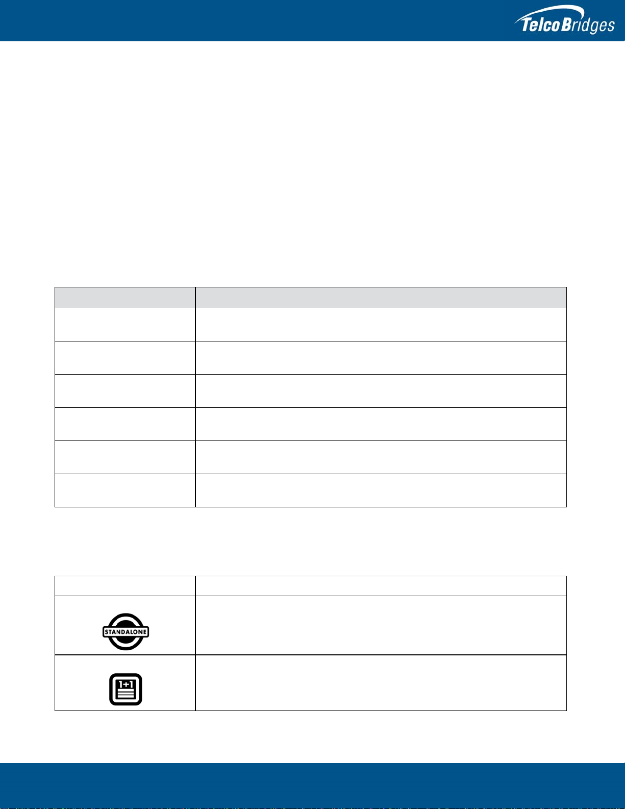
Terminology Description
800 series gateway This term is used when a description applies to both the 800 series standalone and
800 series 1+1 system.
800 series standalone This term is used when a description applies to the 800 series unit operating as a
standalone unit.
800 series 1+1 System This term is used when a description applies to the 800 series unit operating in
conjunction with the 800+1 series unit. This term also includes the 1+1 patch panel.
800 series unit This term is used when a description applies to all variations of the 800 series units,
such as: TMG800, TSG800, and TMGIP800.
800 series +1 unit This term is used when a description applies to all variations of the 800 series +1
units, such as TMG800 +1, TSG800 +1, or TMGIP800 +1.
1+1 Patch Panel This term is used as a generic reference to 1+1 patch panel, which enables an 800
series to connect to an 800 series +1.
To help guide you through the installation of your product, we have produced the following icons. Please take note of
the icon which represents the type of installation you are conducting and follow it throughout this guide to ensure
proper install and set-up.
Graphics Description
This icon appears in the margins of pages describing the 800 series operating as a
standalone unit. If you are installing a standalone unit read and follow the
instructions provided in those sections and pages.
This icon appears in the margins of pages describing the 800 series unit operating in
conjunction with an 800 series +1 and 1+1 Patch Panel. If you are installing a 1+1
System read and follow the instructions provided in those sections and pages.
Preface

800 Series Standalone and 800 Series 1+1 System Installation Guide
iv
Contact Us
If you have comments about this guide or any other TelcoBridges technical

v
Table of Contents
Section 1 Introduction....................................................................................................................... 1
1.1 Recognizing an 800 Series Standalone versus an 800 Series 1+1 System .......................2
1.1.1 800 Series Standalone .......................................................................................................2
1.1.2 800 Series 1+1 System ......................................................................................................2
1.2 Installation Prerequisites.....................................................................................................3
1.3 Preventing Electrostatic Discharge Damage.......................................................................4
1.4 Recommended Reading......................................................................................................4
Section 2 Installing the Equipment................................................................................................... 5
2.1 Package Contents...............................................................................................................6
2.1.1 800 Series Standalone Package Contents..........................................................................6
2.1.2 800 Series +1 System Package Contents...........................................................................7
2.2 Rack Mounting the 800 Series Standalone or the 800 Series 1+1 System ........................9
2.2.1 Prerequisites .......................................................................................................................9
2.2.2 Vertical Placement of the Equipment..................................................................................9
2.2.3 Installing the 800 Series Standalone and the 800 Series 1+1 on an Equipment Rack.....10
2.3 Choosing your Connection Procedures.............................................................................12
2.4 800 Series Standalone......................................................................................................13
2.4.1 Connecting to the 800 Series Gateway Management Interface........................................14
2.4.2 Connecting to a VoIP Network..........................................................................................15
2.4.3 Connecting to the PSTN....................................................................................................16
2.4.4 Powering Up......................................................................................................................17
2.4.4.1 Connecting to AC Power...................................................................................................17
2.4.4.2 Connecting to DC Power...................................................................................................18
2.4.5 Start Up.............................................................................................................................20
2.4.5.1 Configuring the Role..........................................................................................................20
2.5 800 Series 1+1 System.....................................................................................................21
2.5.1 Connecting to the 800 Series 1+1 System Management Interfaces.................................22
2.5.2 Connecting to the 800 Series 1+1 System Control Network and VoIP Network(s)...........23
2.5.3 Connecting to the PSTN in an 800 Series 1+1 System ....................................................24
2.5.4 Powering Up......................................................................................................................26
2.5.4.1 Connecting to AC Power...................................................................................................26
2.5.4.2 Connecting to DC Power...................................................................................................27
2.5.5 Start Up.............................................................................................................................29
2.6 Adding an 800 +1 Unit to an Existing Standalone; Creating an 800 series 1+1 System...31
2.6.1 Reconfigure a Standalone Unit as a Primary Unit in an 800 Series 1+1 System..............31
2.6.2 Install the 800 Series +1 unit on the Equipment Rack ......................................................34
2.6.3 Install the 1+1 Patch Panel ...............................................................................................34
2.6.4 Connect to the 800 Series 1+1 Management Interface.....................................................34
2.6.5 Connect to the 800 Series 1+1 Control Network and VoIP Network(s).............................34
2.6.6 Connect to the PSTN Network..........................................................................................35
2.6.7 Power Up the Equipment ..................................................................................................35
2.6.8 Start Up.............................................................................................................................36
2.7 Verifying the LED Status Indications.................................................................................37

800 Series Standalone and 800 Series 1+1 System Installation Guide
vi
2.8 Powering Down.................................................................................................................38
Section 3 Initial System Configuration............................................................................................ 39
3.1 Connecting to the Serial Port of the 800 Series Gateway.................................................40
3.2 Configuring the Terminal Emulator Application.................................................................42
3.3 Connecting to the 800 Series Gateway.............................................................................42
3.4 Retrieving 800 Series Gateway Information......................................................................43
3.5 Changing the 800 Series Gateway Management Port IP Address ...................................43
3.6 Changing 800 Series Gateway Management Port Passwords .........................................43
3.7 Setting the Time Zone.......................................................................................................43
3.8 Configuring the 800 Series Gateway Using the Web Portal..............................................44
3.9 Changing VoIP Interface Addresses.................................................................................44
Section 4 System Backups............................................................................................................. 45
4.1 Creating a Database Backup ............................................................................................46
4.2 Downloading a Database Backup.....................................................................................46
4.3 Uploading a Database Backup..........................................................................................46
4.4 Restoring a Database Backup...........................................................................................46
Appendix A Wiring Diagrams............................................................................................................. 47
A.1 RJ48C Wiring Diagram: Crossover and Straight Cables...................................................48
A.2 RJ48 Console Wiring Diagram..........................................................................................48
1
Section 1 Introduction
This section provides an introduction to the installation and setup for the following
configurations:
800 Series Standalone: Single gateway unit operating in standalone mode.
800 series 1+1 system: 800 series unit operating in conjunction with an
800 series +1 unit and a 1+1 patch panel.
The following topics are covered:
• Section 1.1 “Recognizing an 800 Series Standalone versus an 800 Series 1+1
System”
• Section 1.2 “Installation Prerequisites”
• Section 1.3 “Preventing Electrostatic Discharge Damage”
• Section 1.4 “Recommended Reading”
800 Series Standalone and 800 Series 1+1 System Installation Guide
2
1.1 Recognizing an 800 Series Standalone versus an 800 Series
1+1 System
1.1.1 800 Series Standalone
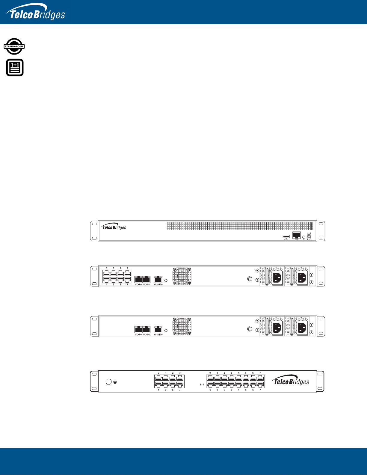
The 800 series standalone consists of one telecom unit. The front and rear views are shown in
figure 1.1 on page 2.
The 800 series standalone consists of one telecom unit. The front and rear views are shown in figure 1.1
on page 2.
1.1.2 800 Series 1+1 System
The 800 series 1+1 system, see figure 1.1 on page 2, consists of:
• One telecom unit
• One +1 telecom unit
• One 1+1 patch panel
Figure 1.1 Equipment Front and Rear Views
1+1 Patch Panel (RJ)
TMG800/TSG800/TMGIP800 (front view)
Network
Gateway
Gateway
1+1 Patch Panel (8 T1/E1)
TMG800/TMG800 + 1 and TSG800/TSG800 +1 (rear view)
TMGIP800/TMGIP800 + 1 (rear view)
3
Introduction
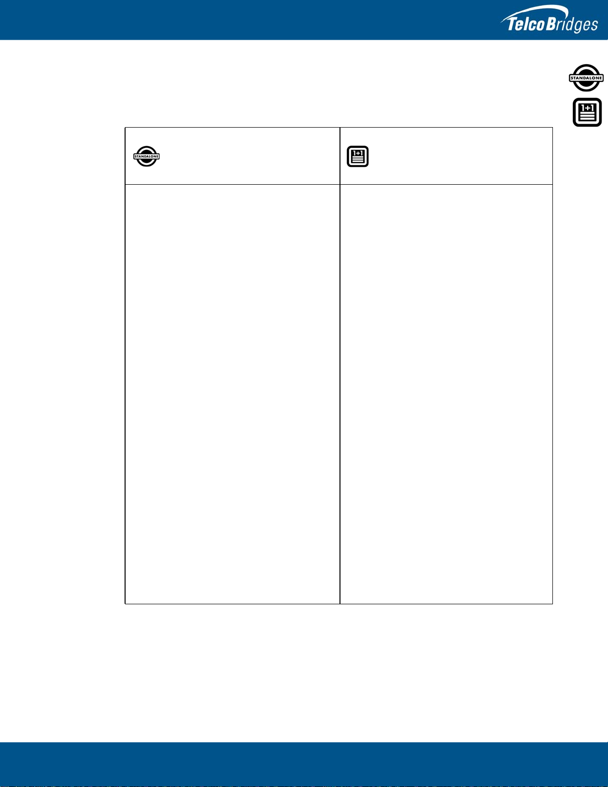
1.2 Installation Prerequisites
For the installation to proceed without interruption, it is important that you verify that you have all
necessary materials on hand.
800 Series Standalone 800 Series 1+1 System
Adequate space for the installation of the 800
series standalone.
You will need to mount the 800 series unit on a
19" equipment rack (customer provided). Your
800 series unit is a 1U unit.
Adequate space for the installation of your
800 series 1+1 system.
You will need to mount the 800 series 1+1
system on a 19" equipment rack (customer
provided).
Your 1+1 System requires space for the
following number of units:
Adequate power supply and power
connections.
The 800 series unit requires one or two power
connections, depending on whether you have
purchased the single or redundant power supply
option. If you have a redundant power supply, to
guarantee an uninterrupted supply of electricity,
each power connection must be fed by a
dedicated power source.
An IP address for the management port.
Toavoid delays,you shouldhave the IPaddress,
netmask and gateway addresses on hand. Take
note that the management port supports DHCP,
see Section 2.4.1 “Connecting to the 800 Series
Gateway Management Interface” on page 14 for
further information.
800 Series Unit:
800 Series +1 Unit:
1+1 Patch Panel:
Total:
1U
1U
1U
3U
Adequate power supply and power
connections.
The 800 series and 800 series +1 units require
one to two power connections each, depending
on whether you have chosen them with single or
redundant power supply. To guarantee an
uninterrupted supply for the instance of dual
power connections, each power connection
must be fed by a dedicated power source.
An IP address for the management port.
To avoid delays, you should have the IP
address, netmask and gateway addresses on
hand. Take note that the management port
supports DHCP, see Section 2.4.1 “Connecting
to the 800 Series Gateway Management
Interface” on page 14 for further information.

800 Series Standalone and 800 Series 1+1 System Installation Guide
4
1.3 Preventing Electrostatic Discharge Damage
Electrostatic discharge (ESD) can damage equipment and impair electrical circuitry. It may occur if
electronic printed circuit cards are improperly handled and may cause complete or intermittent failure.
Always follow ESD prevention procedures when removing and replacing modules:
• Ensure that the equipment is grounded.
• Wear an ESD-preventive wrist strap and ensure that it makes good contact with your
skin. Connect the wrist strap clip to an unpainted surface of the equipment or the
grounded equipment rack in order to channel away all ESD voltage safely to ground.
To guard against ESD damage and shocks, the wrist strap and cord must be in proper
working condition.
• If no wrist strap is available, and you must work with the equipment, ground yourself
by touching a metal part of the chassis.
1.4 Recommended Reading
This document assumes that you have a clear understanding of the installation of the equipment
described in this document and have been trained to work with the equipment.If you have any technical
questions, TelcoBridges TB Support (technical support team) can be reached at the following numbers
• Americas & Europe Technical Support Centre (GMT-05:00, Montreal):
Telephone: +1-450-655-8993 x131 or x102
• Asia Technical Support Centre (GMT +08:00, Hong Kong)
Telephone: +852-3749-9818
• 24/7 International Support
Telephone: +1-866-438-4703
Documents exploring various aspects of the product are available on the TB Wiki:
http://docs.telcobridges.com
!
Warning

5
Section 2 Installing the Equipment
This section provides information about the following topics:
• Section 2.1 “Package Contents”
• Section 2.2 “Rack Mounting the 800 Series Standalone or the 800 Series 1+1
System”
• Section 2.4 “800 Series Standalone”
• Section 2.5 “800 Series 1+1 System”
• Section 2.6 “Adding an 800 +1 Unit to an Existing Standalone; Creating an 800
series 1+1 System”
• Section 2.7 “Verifying the LED Status Indications”
• Section 2.8 “Powering Down”

800 Series Standalone and 800 Series 1+1 System Installation Guide
6
2.1 Package Contents
Depending on your system requirements, you may receive one or more of the following items:
• Section 2.1.1 “800 Series Standalone Package Contents” on page 6.
• Section 2.1.2 “800 Series +1 System Package Contents” on page 7.
The contents of these devices are described in the following sections.
2.1.1 800 Series Standalone Package Contents
TMG800, TSG800, TMGIP800
In the box, you will find the following items:
• One 800 series unit:
TMG800, TSG800, or TMGIP800. See figure 1.1 on page 2.
• One set of mounting brackets and screws, used to mount the 800 series unit to a 19" rack.
• One Tmedia serial adapter to interface the serial port of your computer with the RJ-45 port of the
800 series unit.
• Three CAT5 Ethernet straight cables (male-male), 3 meters in length.
• One Important Notice (two-sided document containing pertinent product serial numbers, and other
important information).
• One Product Warranty.
• One packing slip.
• One Quick Installation Guide (two-sided document that provides a pictorial view of the equipment
setup).
• For AC powered units: One or two AC power cables
• For DC powered units: One or two DC power cables
Not included
• A 19” equipment rack. The 800 series unit must be installed on a 19” wide equipment rack.

7
Installing the Equipment
2.1.2 800 Series +1 System Package Contents
TMG800, TSG800, TMGIP800
In the box, you will find the following items:
• One 800 series unit:
TMG800, TSG800, or TMGIP800. See figure 1.1 on page 2.
• One set of mounting brackets and screws, used to mount the 800 series unit to a 19" rack.
• One Tmedia serial adapter, to interface the serial port of your computer with the RJ-45 port of the
800 series unit.
• Three CAT5 Ethernet straight cables (male-male), 3 meters in length.
• One Important Notice (two-sided document containing pertinent product serial numbers, and other
important information).
• One Product Warranty.
• One packing slip.
• One Quick Installation Guide (two-sided document that provides pictorial view of the equipment set-
up).
• For AC powered units: One or two AC power cables
• For DC powered units: One or two DC power cables
Not included
• A 19" equipment rack. The 800 series unit must be installed in a standard 19" wide equipment rack.
TMG800 +1, TSG800 +1, TMGIP800 +1
• One 800+1 series unit. See figure 1.1 on page 2.
• One set of mounting brackets and screws, used to mount the 800+1 series unit to a 19" rack.
• One Tmedia serial adapter, to interface the serial port of your computer with the RJ-45 port of the
800 series +1.
• Three CAT5 Ethernet straight cables (male-male), 3 meters in length.
• One Important Notice (two-sided document containing pertinent product serial numbers, and other
important information).
• One Product Warranty.
• One packing slip.
• One Quick Installation Guide (two-sided document that provides pictorial view of the equipment set-
up).
• For AC powered units: One or two AC power cables
• For DC powered units: One or two DC power cables
• The associated 1+1 patch panel. See Table 2.1, “1+1 Patch Panels”, on page 8 for further details.
800 Series Standalone and 800 Series 1+1 System Installation Guide
8
Not included:
• A 19" equipment rack. The 800 series +1 unit must be installed in a standard 19" wide equipment
rack.
1+1 Patch Panel
A 1+1 patch panel is required for the proper connection of the 800 series 1+1 system and is
automatically included when a 800 series +1 unit is ordered.
Cables provided: You will be provided with 16 RJ48C cables (yellow), two meters in length with your
1+1 Patch Panel (8 T1/E1).
Table 2.1 1+1 Patch Panels
1+1 Patch Panel (8/T1/E1) Provides connection for up to 8 T1/E1 lines from the network to
the 1+1 Patch Panel (8 T1/E1) and then links to the
TMG800/TSG800 and TMG800 +1/TSG800 +1
Cables provided:
You will be provided with 16 RJ48C cables (yellow), two meters
in length, per 1+1 Patch Panel (8 T1/E1) you receive.

9
Installing the Equipment
2.2 Rack Mounting the 800 Series Standalone or the 800 Series
1+1 System
The 800 series equipment is mounted on a customer provided equipment rack using the mounting
hardware packaged in the box.
2.2.1 Prerequisites
To rack mount the equipment, you will need:
• One 19” customer-provided equipment rack. The rack must be solidly anchored to the floor with
appropriate support at the top of the racks.
• Climate controlled room: 0 to +50 Celsius, 0 to 95% non-condensing humidity.
2.2.2 Vertical Placement of the Equipment
The 800 series standalone, 800 series +1, and 1+1 Patch Panel are each housed in a 1U chassis, as
tabulated in table 2.2 on page 9. It is important that you provide for enough room on the equipment rack
to allow for the installation of the equipment.
Consider the available space on your equipment rack and the height of the 800 series gateway
equipment. Due to the rear-exhaust heat vents and the efficient heat dissipation design, there is no
need to leave any physical vertical space above or below the 800 series gateway equipment on the
equipment rack.
Table 2.2 800 Series Gateway Physical Height
Model Number Vertical Height
800 series standalone 1U (1.75 inches or 44.45 mm)
800 series +1 1U (1.75 inches or 44.45 mm)
Patch Panel 1U (1.75 inches or 44.45 mm)
800 Series Standalone and 800 Series 1+1 System Installation Guide
10
2.2.3 Installing the 800 Series Standalone and the 800 Series 1+1 on an
Equipment Rack
Both the 800 series standalone and the 800 series 1+1 system are mounted on the 19" equipment rack
using the angle brackets and screws provided in the box.
Mounting the 800 Series Standalone:
1. Using four metal screws, attach one angle bracket to the front, left-hand side of the 800 series unit,
when viewed from the front, as shown in figure 2.1 on page 11. Do the same for the angle bracket
on the right-hand side.
2. Start mounting equipment at the top-most position of the rack, keeping in mind the space required
on the equipment rack as described in Section 2.2.2 “Vertical Placement of the Equipment” on
page 9.
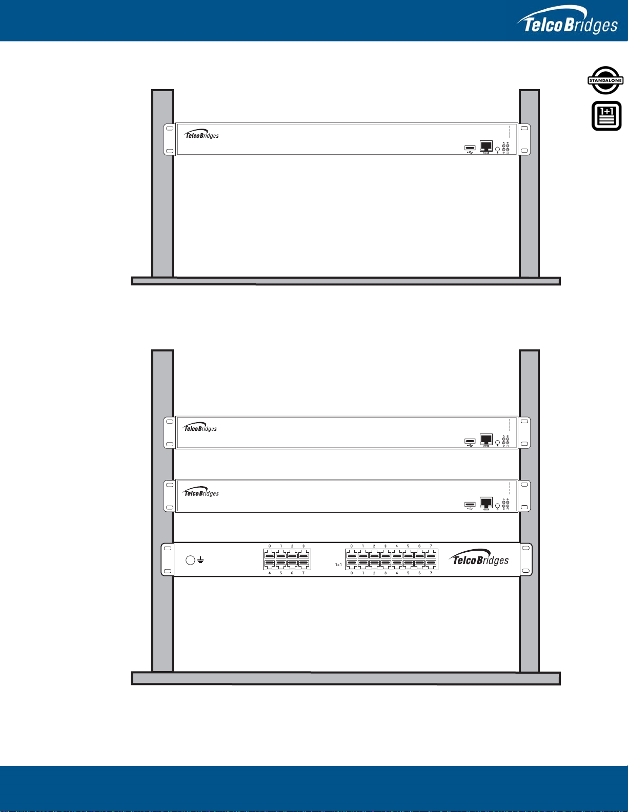
Mounting the 800 Series 1+1 System:
1. Mount the 800 series unit as mentioned above.
2. Install the 800 series +1 unit below the 800 series unit, as shown in figure 2.1 on page 11.
3. To attach the 800 series +1 unit to the equipment rack, follow the previous procedure.
4. Install the patch panel below the 800 series +1 unit, as shown in figure 2.1 on page 11.
11
Installing the Equipment
Figure 2.1 Rack Mounting the Equipment
800 Series Unit
800 Series +1 Unit
1+1 Patch Panel
800 Series Unit
800 Series Standalone
800 Series 1+1 System
Network
Gateway
Gateway
1+1 Patch Panel (8 T1/E1)
800 Series Standalone and 800 Series 1+1 System Installation Guide
12
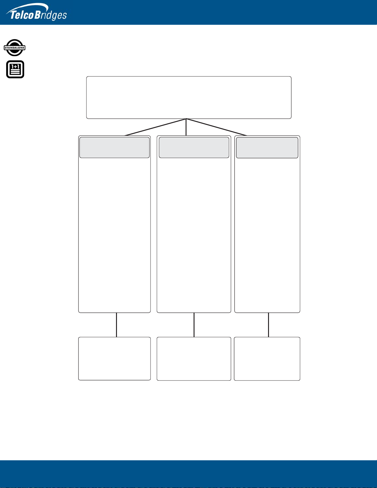
2.3 Choosing your Connection Procedures
Use the following diagram to guide you to the appropriate section, based on your chosen installation.
Choosing Your Setup
800 Series
Standalone
I am setting
up an
800 series
as a
standalone
unit
I am setting up an
800 series
1+1 system
including:
an 800 series unit,
800 series +1
and a 1+1patch
panel,
creating a
redundant system
Go to
Section 2.4
I am adding
an 800 series +1
to an existing
system;
Creating an
800 series 1+1
system
800 Series 1+1
System
Adding a Unit
Go to
Section 2.5
Go to
Section 2.6

13
Installing the Equipment
2.4 800 Series Standalone
If you are here, you have a 800 series unit that you will set up as a standalone system. This section
covers the following procedures:
• Section 2.4.1 “Connecting to the 800 Series Gateway Management Interface”.
• Section 2.4.2 “Connecting to a VoIP Network”.
• Section 2.4.3 “Connecting to the PSTN”.
• Section 2.4.4 “Powering Up”.
• Section 2.4.5 “Start Up”.

800 Series Standalone and 800 Series 1+1 System Installation Guide
14
2.4.1 Connecting to the 800 Series Gateway Management Interface
The 800 series gateway management Interface enables administrators to perform management tasks
on the 800 series unit.
Prerequisites
To communicate with the management interface, the following is needed:
• One CAT5 Ethernet cable with RJ45 male-male terminations.
Interconnections
The 800 series gateway provides a management interface using one gigabit ethernet network link, as
shown in figure 2.2 on page 14.
To communicate with the management interface:
1. Connect the supplied CAT5 ethernet cable to the port labelled “MGMT0” at the rear of the 800
series gateway.
Figure 2.2 Management Interface
Management Interface Ethernet Switch
Other manuals for Tmedia TMG800
2
This manual suits for next models
2
Table of contents
Other TelcoBridges Gateway manuals

TelcoBridges
TelcoBridges TMG3202 User manual

TelcoBridges
TelcoBridges TMP6400 User manual

TelcoBridges
TelcoBridges 7800 Series User manual

TelcoBridges
TelcoBridges TMG7800 User guide

TelcoBridges
TelcoBridges Tmedia TMG800 User manual

TelcoBridges
TelcoBridges TMG3202 User manual

TelcoBridges
TelcoBridges 3200 Series Gateway Standalone User manual

TelcoBridges
TelcoBridges Tmedia TMG3200 User manual

TelcoBridges
TelcoBridges Tmedia TMG3200 User guide

TelcoBridges
TelcoBridges TMG7800 User guide


