- Vor dem Gebrauch des Werkzeugs sicherstellen, dass sich
eine Absperrvorrichtung in der Zufuhrleitung befindet. Die
Lage dieser Absperrvorrichtung muss bekannt und leicht
zuqanqlich sein, um die Luftzufuhr im Notfall abstellen zu
konnen.
- Den Schlauch und die Anschlussstucke regelmaBig auf
Abnutzung untersuchen.
- Darauf achten, dass sich die beweglichen Teile des
Werkzeugs nicht in Kleidung, Haar, Krawatten,
Reinigungstuchern, Ringen, Schmuck, Armbanduhren,
Armbandern usw. vertangen konnen. Dies konnte dazu
fuhren, dass der menschliche Korper oder Korperteile in
Richtung Werkzeug gezogen werden, was zum auBerst
gefahrlichen Kontakt mit den beweglichen Teilen des
Werkzeugs fUhren konnte,
- Es wird erwartet, dass Bediener sichere Arbeitspraktiken
anwenden und dass sie aile ortltchen, regional en oder
landerspezihschen Vorschriften bei der Montage, dem
Gebrauch und der Wartung des Werkzeugs beachten.
- Sicherstellen, dass die Abluft nicht auf andere Personen
bzw, Materialien oder Substanzen gerichtet wird, die durch
Olspritzer verunreinigt werden konntsn. Beim ersten
Schmieren des Werkzel, gs oder wenn die Abluft des
Werkzeugs einen hohen Olgehalt aufweist, dart die Abluft
nicht in die Nahe yon sehr heiBen Obertlacnsn oder
Flammen gelangen.
- Niemals das Werkzeug ablegen, solange der
Arbeitsaufsatz noch lauft,
Bei Nichtgebrauch des Werkzeugs die Luftzufuhr abstellen
und mit dem Ausloser/Hebel die Luft aus der Zufuhrleitung
ablassen. Wenn das Werkzeug fur Ianqere Zeit nicht
benutzt wird, es zunachst schmieren, yon der Luftzufuhr
abtrennen und an einem trockenen Ort bei
durchschnittlicher Raumtemperatur lagern.
- Wenn das Werkzeug an einen neuen, unerfahrenen
Benutzer weitergegeben wird, sicherstellen, dass auch
diese Anleitungen zusammen mit dem Werkzeug
Oberqabsn werden.
- Keine vom Herstelier am Werkzeug angebrachten
Sicherheitsvorrichtungen entfernen oder verschieben. Die
gilt fUr Schleifscheibenschutzhauben, Slcherheltsausloser,
Drehzahlregler usw.
- Wenn moqlich das Werkstuck mit Klemmzwingen, einem
Schraubstock usw. sichern, damit es sich wahrsnd der
Bearbeitung nicht verschiebt. Jederzeit die Balance
wahren, und sich nicht uberstrscken oder versuchen, zu
weit entfernt liegende Werkstucke zu erreichen.
- Fur jeden Arbeitsvorgang das passende Werkzeug
verwenden. Niemals ein zu leichtes oder zu schweres
Werkzeug fUr einen Arbeitsvorgang verwenden. 1mZweifel
einen Fachmann um Rat bitten.
- 1mAligemeinen kann dieses Werkzeug nicht unterWasser
oder in einer Umgebung mit Explosionsgefahr verwendet
werde. Fragen Sie den Hersteller um Rat.
Sicherstellen, dass der Arbeitsbereich aufgeraumt ist, um
die Arbeit sicher ausfUhren zu konnen, Wenn rnoqlich,
unnotige Hindernisse vor dem Arbeitsbeginn aus dem Weg
raurnsn.
- Immer Luftschlauche und VerbindungsstQcke verwenden,
die einem nominalen Arbeitsdruck yon wenigstens dem 1
1 2
fachen des H6chstarbeitsdrucks des Werkzeugs
standhalten.
Vorgesehener Einsatzbereich
des Werkzeugs - 5272A 5273A
5274A
Dieses Werkzeug ist zum AbmeiBeln, Vernieten und Abkloplen van
Metallen und Gestein vorqesehen. Ein Ireier Hubkolben scnlaqt auf
den Meif3el oder das AulsatzstOck. Beim Hersteller kann eine Liste
mit tur dieses Werkzeug geeigneten Zubeh6rteilen angelordert
werden. Dieses Werkzeug nur in den dalOr vorgesehenen
Anwendungsbereichen einsetzen, nachdem zuvor der Hersteller oder
einer seiner Vertraqshandler um Rat gelragt wurde.
Das Werkzeug niemals tur andere Anwendungszwecke oder tur
seinen Einsatz als MeiBel usw. in irgendeinerWeise verandern, ohne
zuvor den Hersteller oder einen seiner Vertragshiindler um Rat zu
Iragen.
Page NoB
Arbeitsstationen
Das Werkzeug sollte nur als mit der Hand gehaltenes und bedientes
Werkzeug eingesetzt werden. Es wird emplohlen, das Werkzeug nur
in einer standlesten Position zu benutzen. Es kann in anderen
Positionen verwendet werden, wobei der Bediener sich jedoch in
einer sicheren Position mit lestem Halt und sicherer StOtze belinden
muss. Er muss mit den besonderen VorsichtsmaBnahmen vertraut
sein, die beim Betreiben eines Drucklufthammers beachtet werden
mOssen.
Inbetriebnahme
uftzufuhr
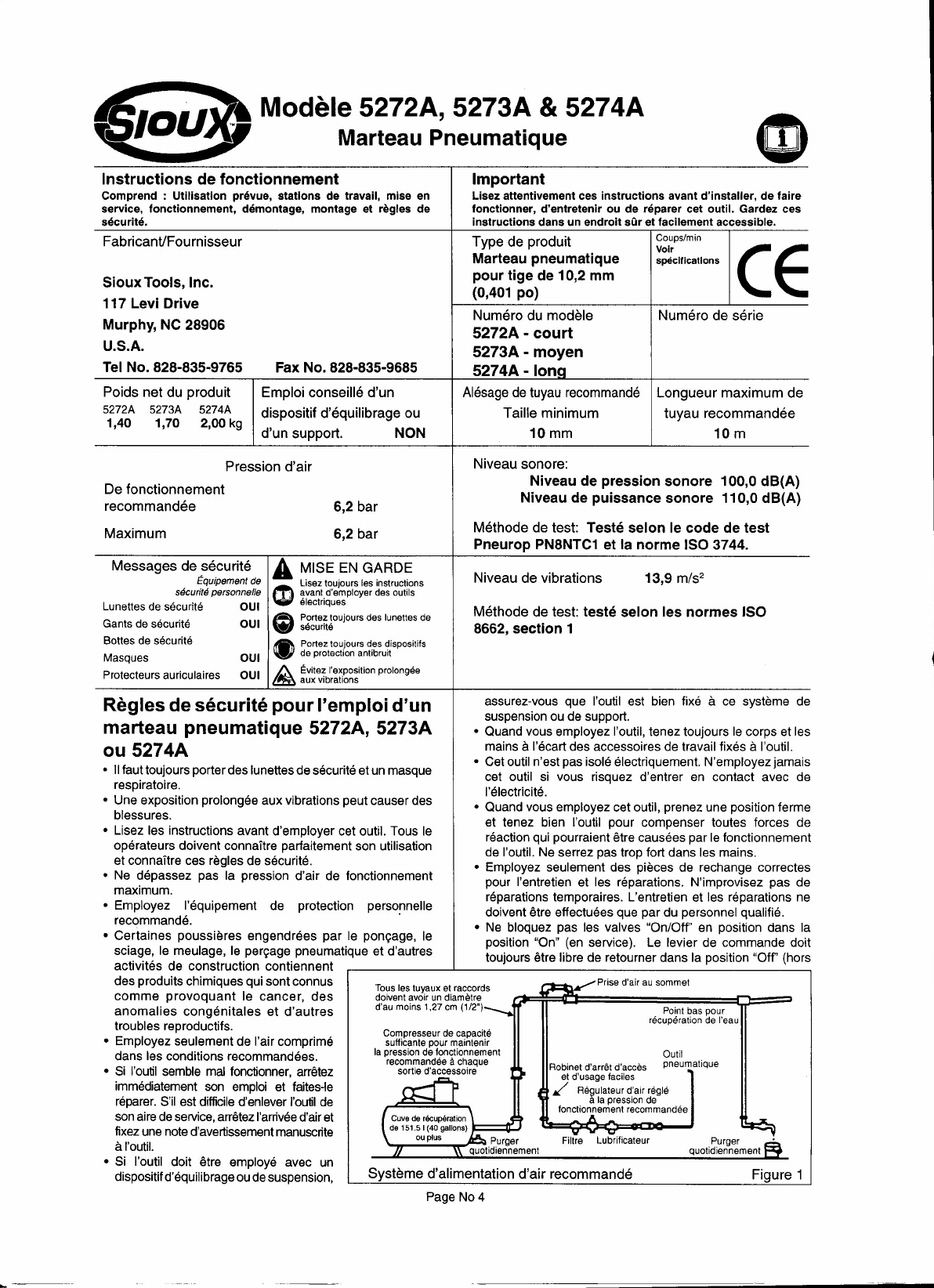
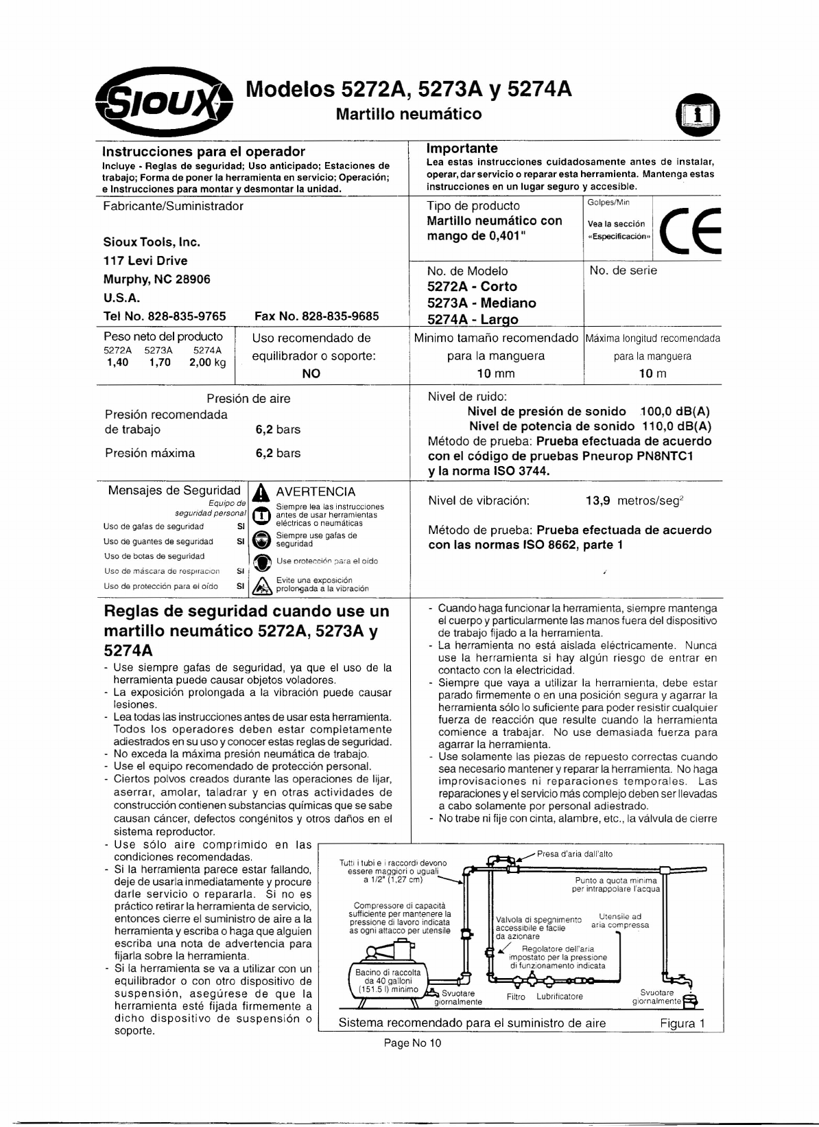
Eine saubere, geschmierte Luftzuluhr verwenden, die dem laufenden
Werkzeug einen regulierten Lultdruck Yon 6,2 bar zufuhrt, wenn der
Drosselklappenhebel ganz herunter gedriickt wird. Die empfohlene
Schlauchgr6Be· und -Ianqe verwenden. Es wird emplohlen, das
Werkzeug an eine wie in Abbildung 1 gezeigte Luftzuluhr
anzuschlieBen. Das Werkzeug nicht an ein Luftleitungssystem ohne
eingebautes, leicht zu erreichendes und zu bedienendes
Luftabsperrventil anschlieBen. Die Luftzuluhr sollte geschmiert sein.
Es wird dringend emplohlen, dass ein Luftfilter, Regier und eine
Schmiervorrichtung (FRL), wie in Abbildung 1gezeigt, verwendet
wird, um saubere, geschmierte Luft mit dem ordnungsgemaBen Druck
zum Werkzeug zu leiten. Ihr Lielerant kann Ihnen Einzelheiten Ober
eine solche Anlage zurVerfOgung stellen. Wenn eine solche Anlage
nicht verwendet wird, sollte das Werkzeug geschmiert werden, indem
die Lultzuluhr zurn Werkzeug abgeschaltet wird und der Druck aus
der Leitung durch DrOcken des Drosselklappenhebels am Werkzeug
abgelassen wird. Die Lultleitung abtrennen, und in den
Schlauchadapter einen Teel6ffel (Sml) lOr pneumatische Motoren
geeignetes Schmier61 gieBen, das ein Rostschutzmittel enthalten
sollte. Das Werkzeug wieder an die Luftzuluhr anschlieBen, und es
einige Sekunden langsam laulen lassen, um das 01 mit der Luft
zirkulieren zu lassen. Wenn das Werkzeug oft benutzt wird, es taglich
schmieren. AuBerdem sollte es geschmiert werden, wenn es langsam
startet oder seine Leistungsfahigkeit ni l'chlaBt.
Der emplohlene an das laufende Werkzeug anzulegende Lultdruck
brtraqt 6,2 bar.
Betrieb
Bei abgetrennter Druckluftzufuhr einen geeigneten MeiBel bzw. ein
geeignetes Zubeh6rteil auswahlen, das sich zur Erledigung der
geplanten Arbeit eignet. Das Schnellwechsel-Spannlutter (23) kann
nur MeiBel mit einem Durchmesser yon 10,2 mm (0,401 Zoll)
aulnehmen. Diese MeiBel werden schnell wie lolgt eingespannt. Das
Schnellwechsel-Spannfutter (23) am Zylinderende (21) mit Gewinde
(spitz zulaulend) schrauben. Mit einem Sechskantschliissel die drei
Sechskantschrauben unten am Spannlutter gegen den Zylinder
festziehen, um zu verhindern, dass sich das Spannlutter aufgrund
van Vibrationen drehen kann. Dann zum Installieren des MeiBels
den texturierten Ring am Spannlutter an den Zylinder zuruckziehen
und den MeiBel in das Spannlutter stecken, bis das Bund die vier
Stahlkugeln passiert hat. Den texturierten Ring tostassen, und
sicherstellen, dass der MeiBel lest eingespannt ist.
FOr den Gebrauch der Federsicherung die Feder mit einer
Rechtsdrehung auf den mit einem Gewinde versehenen Zylinder
schrauben. Den MeiBel durch die Feder vorn Antriebsende aus
einstecken. Das kleine Ende der Feder muss zum Arbeitsende des
MeiBels weisen. Die Feder auf eine Seite schieben, so dass sie in
das AuBenrandfiansch der MeiBelspitze greift.
Niemals einen MeiBel mit angeschlossener Luftzuluhr einspannen,
weil ein unvorhergesehenes Anlaulen zum Herausschleudern des
MeiBels und zu Personenschaden fOhren kann.
Der Druckschalterknopl (14) ist das Ein-/Ausschaltventil des
Werkzeugs. Der Leistungsregler (6) unten am Griff reguliert den
Druckluftzulluss zum Kolben und damit die Schlaghaufigkeit und -
starke.
In der Einlassbuchse (3) belindet sich ein Luftsieb. Dieses regelmaBig
auf Versloplungen untersuchen. Dies gilt insbesondere, wenn das
Werkzeug langsamer lault oder weniger leistet. Zum Reinigen des
Siebs die Drucklufteinlassbuchse (3) abnehmen.