1
PAGE
Repair Instructions No.176.11/96
PB 6S
Special Tools
Required
■
Adjustment tool for carbon brushes 9170 3022 60
■
Pulling-off device 9170 0314 440
Important!
■
Before beginning the maintenance work, perform an initial check with a high voltage test according
to VDE (see chapter Electrical and Mechanical Test Instructions).
■
Before all repair work, pull the power plug from the socket!
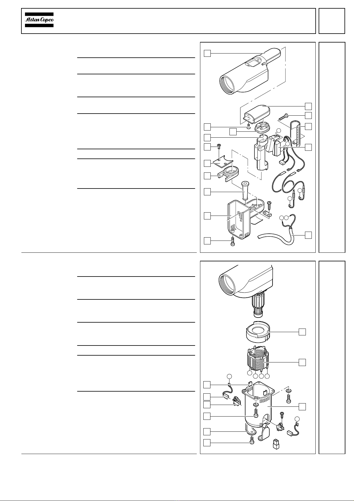
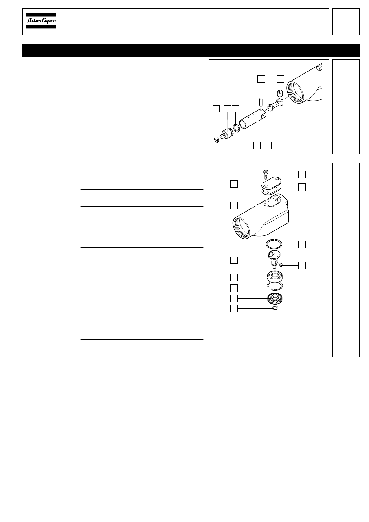
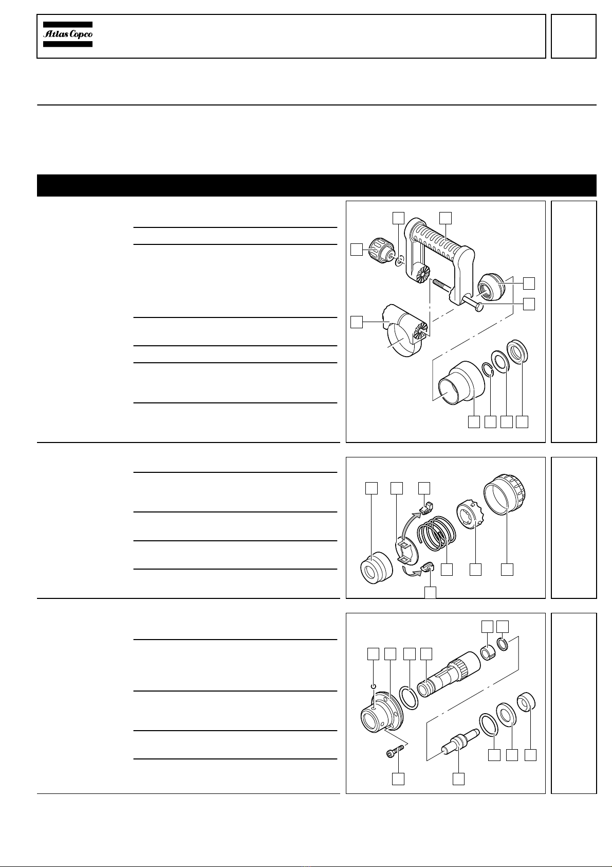
Disassembly
Removing the
auxiliary handle
1
Unscrewthenut(2)andremovethewash-
er (3).
2
Pull out the screw (6).
3
☞
Press the clamping ring (1) and re-
move the auxiliary handle (4). Release
the tension and remove the clamping
ring (1).
4
Push back the rubber sleeve (A) and lever
off the rubber bushing (5).
5
Remove the rubber sleeve (A).
6
Remove the locking ring (9) with aid of cut
special pliers. If necessary, use a screw-
driver for support.
7
Remove the damping element (8) and the
damper (7).
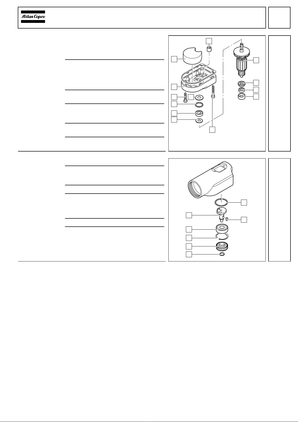
Disassembling
the ball holding
device
1
Remove the locking sleeve (1).
2
Depress the retaining plate (2) against re-
silience - the locking levers (3) are re-
leased. Remove the locking levers (3).
3
Release the retaining plate (2) and re-
move the pressure spring (6).
4
Remove the locking bolt (4) together with
the ball holding device (5).
5
Remove the ball holding device (5) from
the locking bolt (4).
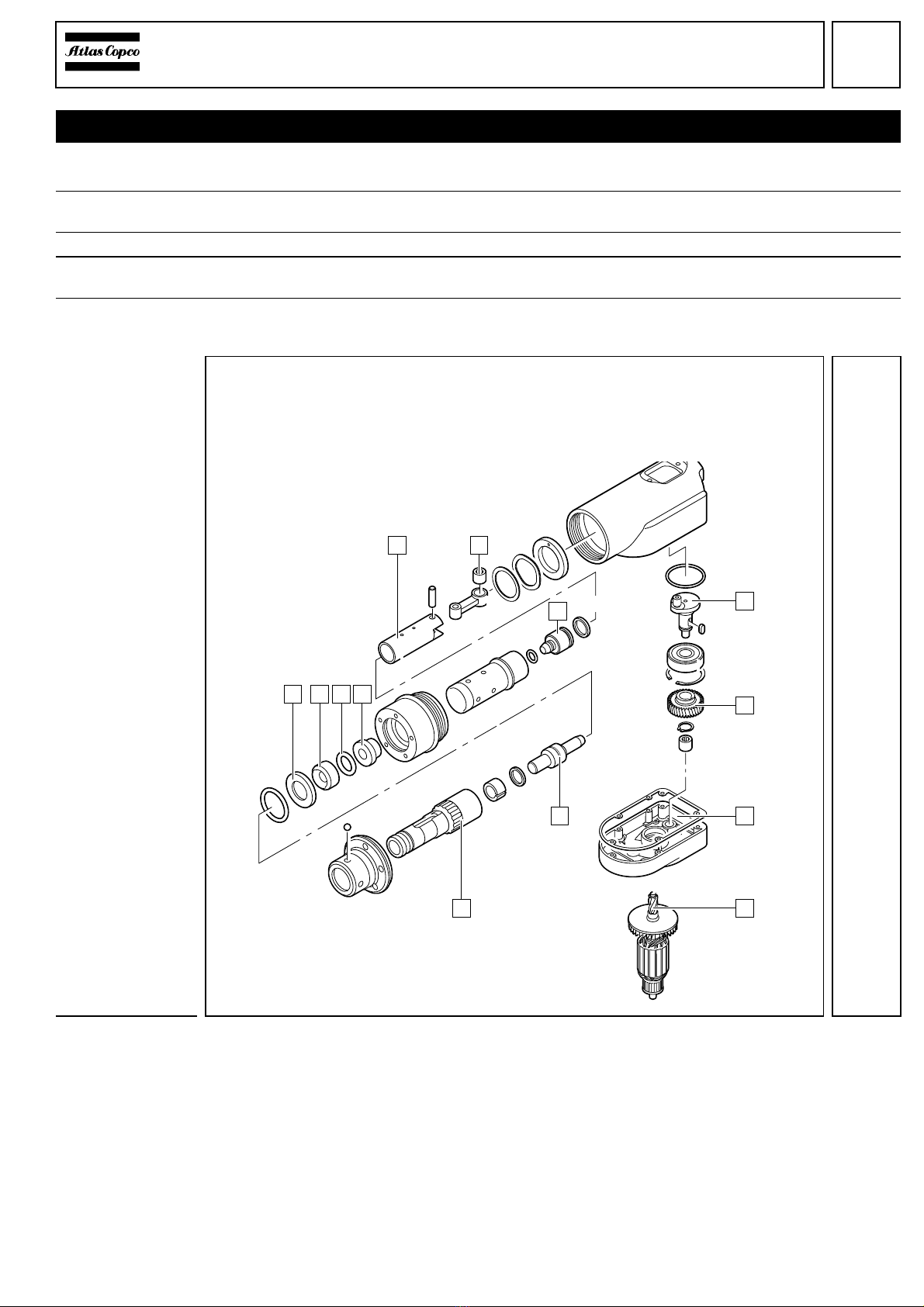
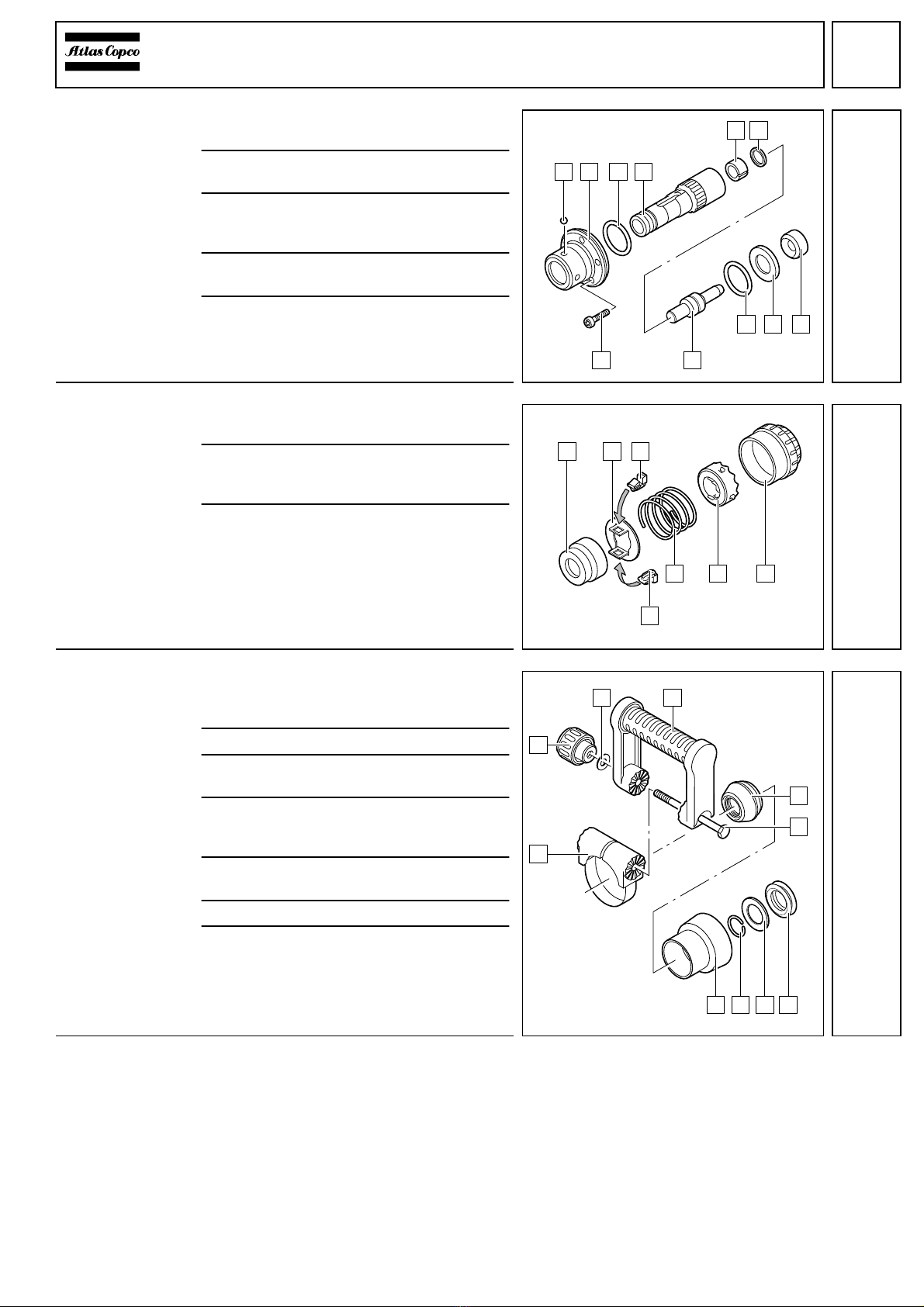
Disassembling
the tool
acceptance
1
Remove all four balls (1) with aid of a mag-
net.
2
Loosen the five screws (B) of the adapter
sleeve (2) and remove the adapter
sleeve (2) as well as the O-ring (3). If nec-
essary, hit it lightly with a plastic hammer.
3
Remove the tool acceptance (4) com-
pletely with the snap die (A), the
spacer (5) and the gasket (6).
4
Remove the snap die (A) from the tool ac-
ceptance (4).
5
Remove the O-ring (9), the spacer (8), as
well as the recoil ring (7).
1
2
8 7
6
4
5
A 9
3
1 2 3
456
1 2 4
5 6
789
AB
3
3