manuals.online logo
Brands
  1. Home
  2. •
  3. Brands
  4. •
  5. Sistemalux
  6. •
  7. Landscape Lighting
  8. •
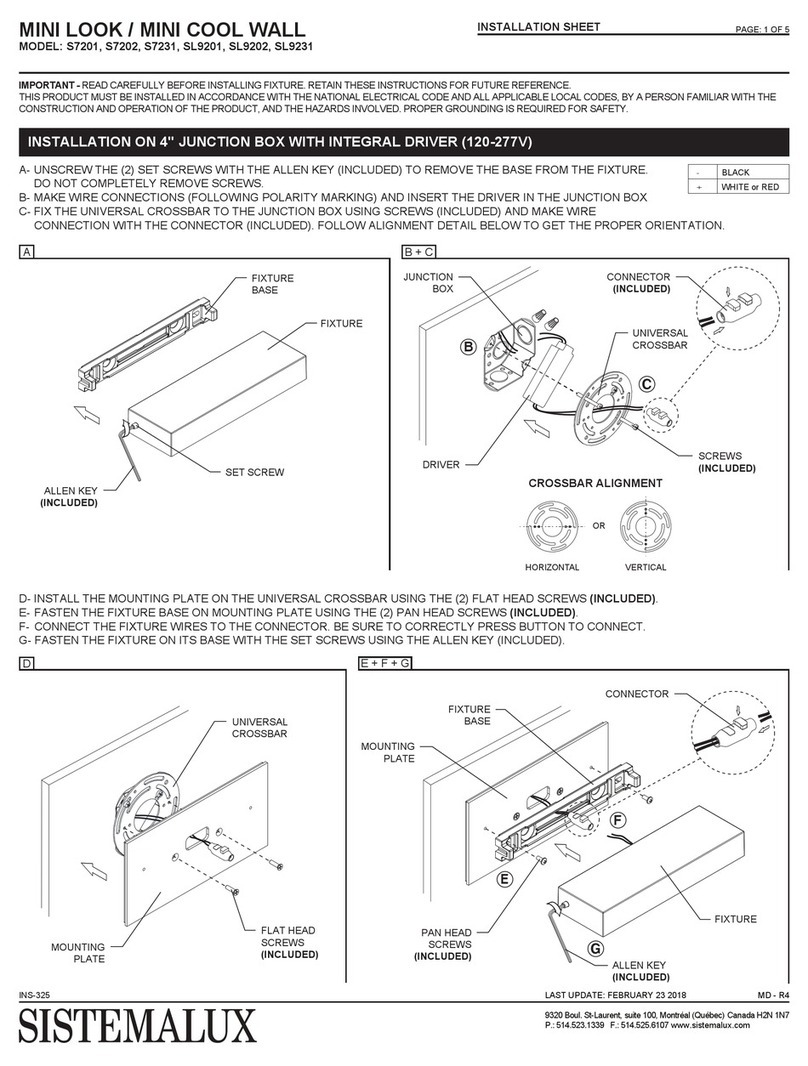
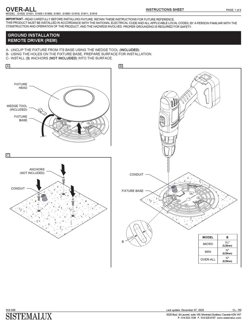
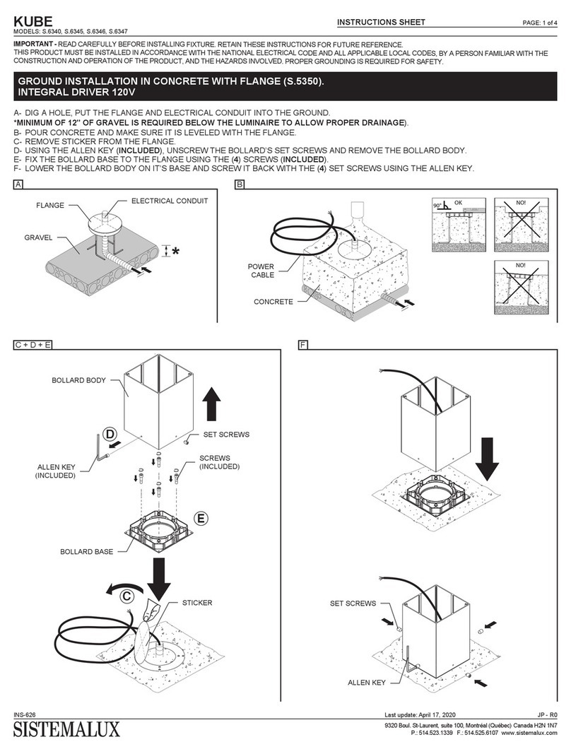
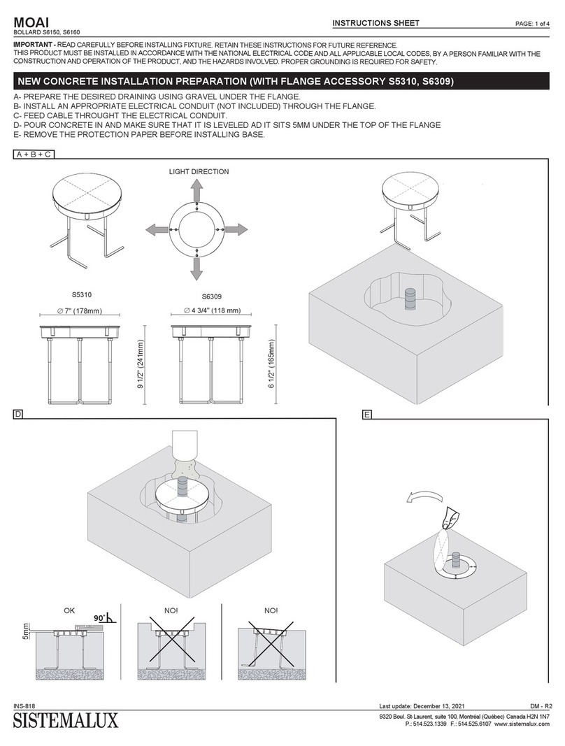
  9. Sistemalux MINI LOOK User manual

Sistemalux MINI LOOK User manual

8½" x 1¼" x 9¼" (217 x 33 x 235mm)
Flange dimensionsFlange code
MINI LOOK S.7206, S.7211, S7215, S.7220, S.L9206, S.L9211 S7249
8½" x 1¾" x 9¼" (290 x 43 x 231mm)
S7269
MINI COOL S.7236, S.7241, S.L9236, S.L9241
LOOK S.7260, S.7261, S.7262, S.7265, S.7266, S.7267
COOL S.7245, S.7246
3¾" x 1¾" x 6⅝" (96 x 45 x 167mm)
S7284
MICRO COOL SQUARE S.7287
5⅝" x 3⅝" x 9⅞ (149 x 66 x 251mm)
S7288
MINI COOL SQUARE S.7286
8½" x 3⅜" x 9⅞ (217 x 85 x 250mm)
S7289
COOL SQUARE S.7285
Model Model Code
LOOK / COOL
BOLLARD
INSTRUCTIONS SHEET PAGE: 1 of 3
INS-532
9320 Boul. St-Laurent, suite 100, Montréal (Québec) Canada H2N 1N7
P.: 514.523.1339 F.: 514.525.6107 www.sistemalux.com
JP - R3Last update: February 18, 2020
IMPORTANT - READ CAREFULLY BEFORE INSTALLING FIXTURE. RETAIN THESE INSTRUCTIONS FOR FUTURE REFERENCE.
THIS PRODUCT MUST BE INSTALLED IN ACCORDANCE WITH THE NATIONAL ELECTRICAL CODE AND ALL APPLICABLE LOCAL CODES, BY A PERSON FAMILIAR WITH THE
CONSTRUCTION AND OPERATION OF THE PRODUCT, AND THE HAZARDS INVOLVED. PROPER GROUNDING IS REQUIRED FOR SAFETY.
GROUND INSTALLATION IN CONCRETE WITH FLANGE.
INTEGRAL DRIVER 120-277V (UNV)
A
A- DIG A HOLE (SEE DIMENSION BELOW), PUT THE FLANGE AND ELECTRICAL CONDUIT INTO THE GROUND. POUR CONCRETE AND MAKE
SURE IT IS LEVELED WITH THE FLANGE.
*MINIMUM OF 12" OF GRAVEL IS REQUIRED BELOW THE LUMINAIRE TO ALLOW PROPER DRAINAGE).
MIN
56mm
OK
90°
NO!
NO!
CONCRETE
MIN
12"
(305mm)
FLANGE
GRAVEL
ELECTRICAL CONDUIT
ALLEN KEY
(INCLUDED)
MOUNTING BASE
LOOK / COOL
BOLLARD
INSTRUCTIONS SHEET PAGE: 2 of 3
INS-532
9320 Boul. St-Laurent, suite 100, Montréal (Québec) Canada H2N 1N7
P.: 514.523.1339 F.: 514.525.6107 www.sistemalux.com
JP - R3Last update: February 18, 2020
B- UNFASTEN THE SCREWS WITH ALLEN KEY (INCLUDED) AND PULL MOUNTING BASE OFF THE MAIN BODY.
C- FASTEN THE MOUNTING BASE TO THE FLANGE USING (2) FLANGE NUTS (INCLUDED).
D- MAKE WIRE CONNECTIONS (FOLLOWING POLARITY MARKING) USING WATERTIGHT TWIST CONNECTORS (NOT INCLUDED).
E- PLACE MAIN BODY ONTO THE MOUNTING BASE AND FASTEN THE SCREWS WITH AN ALLEN KEY (INCLUDED).
B
SCREWS
MOUNTING BASE
WATERTIGHT
TWIST CONNECTORS
(NOT INCLUDED)
SCREWS
MAIN BODY
D
D
E
C + D + E
LIVE BLACK
NEUTRAL WHITE
GREEN
C
FLANGE NUTS
(INCLUDED)
LOOK / COOL
B- UNFASTEN THE SCREWS WITH ALLEN KEY (INCLUDED) AND PULL MOUNTING BASE OFF THE MAIN BODY.
C- FASTEN THE MOUNTING BASE TO THE SURFACE USING (2) APPROPRIATE WOOD OR CONCRETE ANCHOR SCREWS (NOT INCLUDED).
D- MAKE WIRE CONNECTIONS (FOLLOWING POLARITY MARKING) USING WATERTIGHT TWIST CONNECTORS (NOT INCLUDED).
E- PLACE MAIN BODY ONTO THE MOUNTING BASE AND FASTEN THE SCREWS WITH AN ALLEN KEY (INCLUDED).
3"
(75mm)
MINI LOOK / MINI COOL
2⅛"
(55mm)
MICROCOOL SQUARE
2"
(49mm)
⅞"
(22mm)
2½"
(65mm)
⅞"
(22mm)
MINICOOL SQUARE
4¾"
(120mm)
1⅜"
(36mm)
COOL SQUARE
LOOK / COOL
BOLLARD
INSTRUCTIONS SHEET PAGE: 3 of 3
INS-532
9320 Boul. St-Laurent, suite 100, Montréal (Québec) Canada H2N 1N7
P.: 514.523.1339 F.: 514.525.6107 www.sistemalux.com
JP - R3Last update: February 18, 2020
B
MOUNTING BASE
WATERTIGHT
TWIST CONNECTORS
(NOT INCLUDED)
SCREWS
MAIN BODY
D
E
C + D + E
LIVE BLACK
NEUTRAL WHITE
GREEN
ALLEN KEY
(INCLUDED)
MOUNTING BASE
SCREWS
GROUND INSTALLATION ON ALTERNATIVE SURFACE WITHOUT FLANGE.
INTEGRAL DRIVER 120-277V (UNV)
C
MAX
5
⁄
16
" (8mm)
ANCHOR SCREWS
(NOT INCLUDED)

This manual suits for next models

27

Other Sistemalux Landscape Lighting manuals

Sistemalux MINI LOOK Assembly instructions

Sistemalux

Sistemalux MINI LOOK Assembly instructions

Sistemalux MINI LOOK User manual

Sistemalux

Sistemalux MINI LOOK User manual

Sistemalux S1920 User manual

Sistemalux

Sistemalux S1920 User manual

Sistemalux KUBE User manual

Sistemalux

Sistemalux KUBE User manual

Sistemalux MOAI User manual

Sistemalux

Sistemalux MOAI User manual

Popular Landscape Lighting manuals by other brands
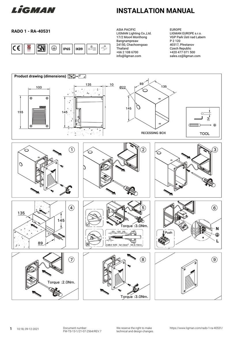
LIGMAN RADO 1 installation manual

LIGMAN

LIGMAN RADO 1 installation manual

Techmar Garden Lights ACIS manual

Techmar

Techmar Garden Lights ACIS manual

TIME LED IP65 GU10 Installation and operating instructions

TIME LED

TIME LED IP65 GU10 Installation and operating instructions

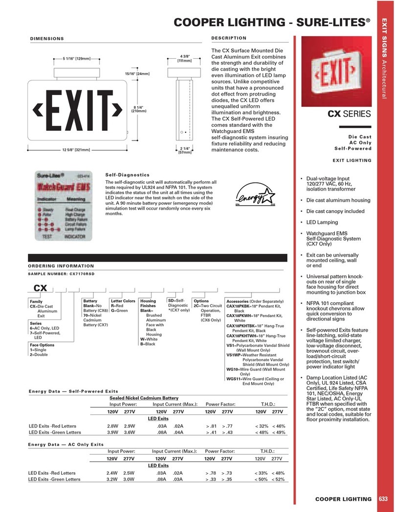
Cooper Lighting CX Series specification

Cooper Lighting

Cooper Lighting CX Series specification

Volt VAL-2002 installation instructions

Volt

Volt VAL-2002 installation instructions

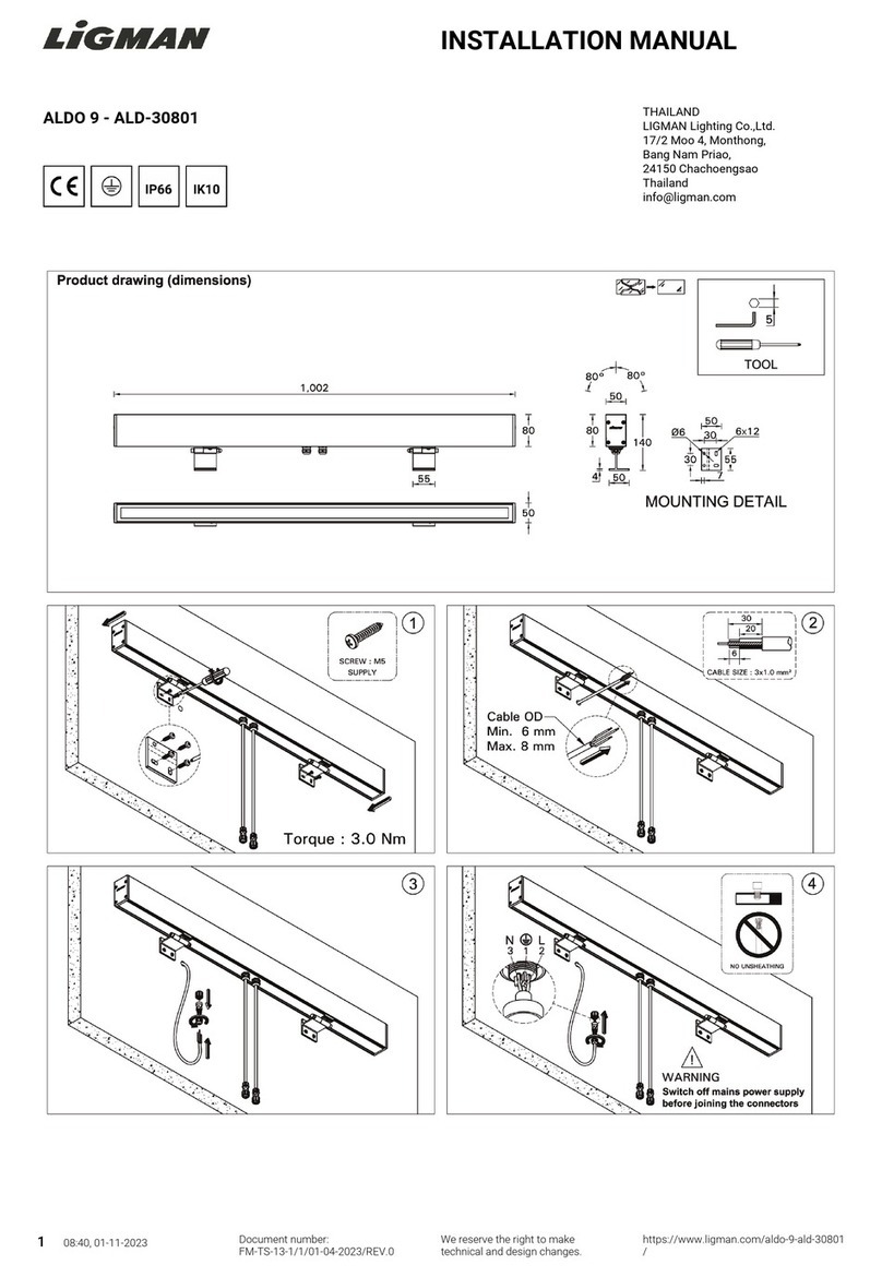
LIGMAN ALDO 9 installation manual

LIGMAN

LIGMAN ALDO 9 installation manual

Chauvet COLORado 6 user manual

Chauvet

Chauvet COLORado 6 user manual

MULTIQUIP GloBug GB3LED Operation and parts manual

MULTIQUIP

MULTIQUIP GloBug GB3LED Operation and parts manual

LIGMAN LUNAR 1 LAN-90002 installation manual
LIGMAN

LIGMAN LUNAR 1 LAN-90002 installation manual

Cooper Lighting Flat Glass OVF15SWW2D4 Specification sheet

Cooper Lighting

Cooper Lighting Flat Glass OVF15SWW2D4 Specification sheet

Philips Broadway Road Lighting brochure

Philips

Philips Broadway Road Lighting brochure

Cooper MODEL 4  LED STYLE III L-852T instruction manual
Cooper

Cooper MODEL 4 LED STYLE III L-852T instruction manual

LIGMAN LIGHTALK 12 installation manual
LIGMAN

LIGMAN LIGHTALK 12 installation manual

Malibu Boats CS508S instructions

Malibu Boats

Malibu Boats CS508S instructions

Pentair Underwater Light Amerlite owner's manual
Pentair

Pentair Underwater Light Amerlite owner's manual

Cooper Lighting McGraw-Edison PFM Specification sheet
Cooper Lighting

Cooper Lighting McGraw-Edison PFM Specification sheet

Dot-Spot brilliance 24 V monochrome Operator's manual

Dot-Spot

Dot-Spot brilliance 24 V monochrome Operator's manual

Volt 3601 Series installation instructions

Volt

Volt 3601 Series installation instructions

manuals.online logo
manuals.online logoBrands
  • About & Mission
  • Contact us
  • Privacy Policy
  • Terms and Conditions

Copyright 2025 Manuals.Online. All Rights Reserved.