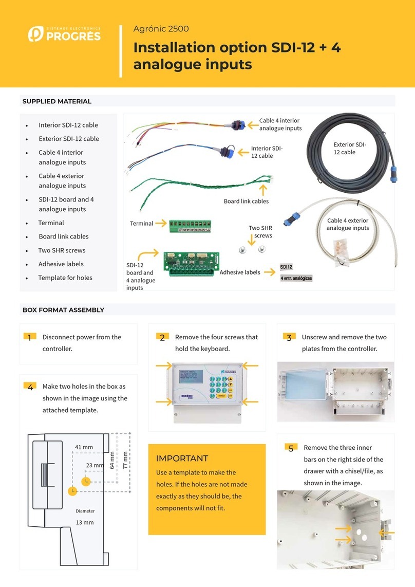
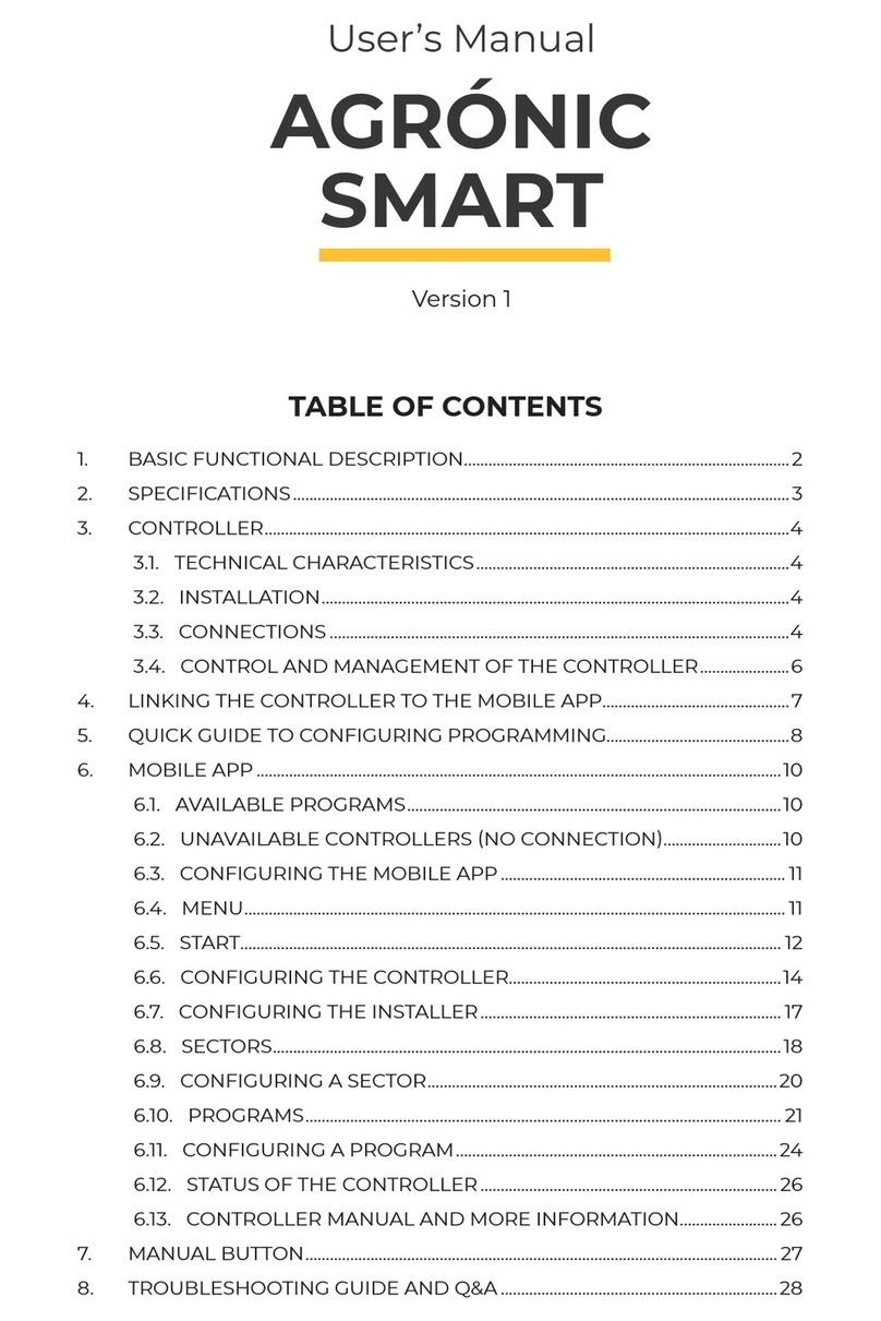
Sistemes Electronics Progres Agronic 2500 User manual
Other Sistemes Electronics Progres Controllers manuals
Popular Controllers manuals by other brands
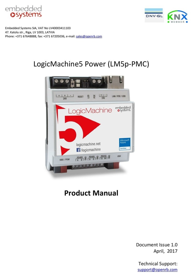
Embedded Systems
Embedded Systems LogiMachine5 Power product manual
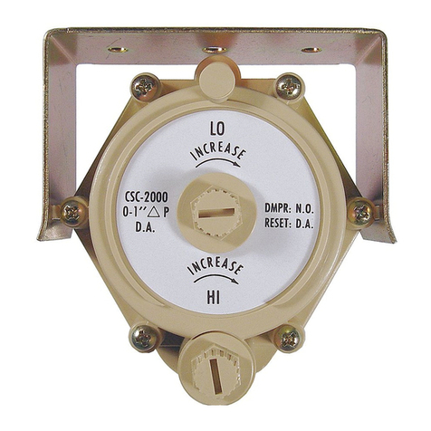
KMC Controls
KMC Controls CSC 3000 Series Application guide

Chess
Chess Mymesh MultiSensor Installation instruction
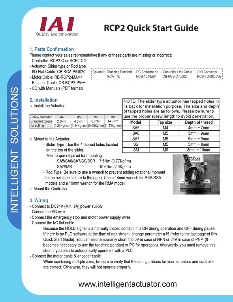
IAI
IAI ROBO Cylinder RCP2 Series quick start guide

Warner
Warner 1300-78 installation instructions
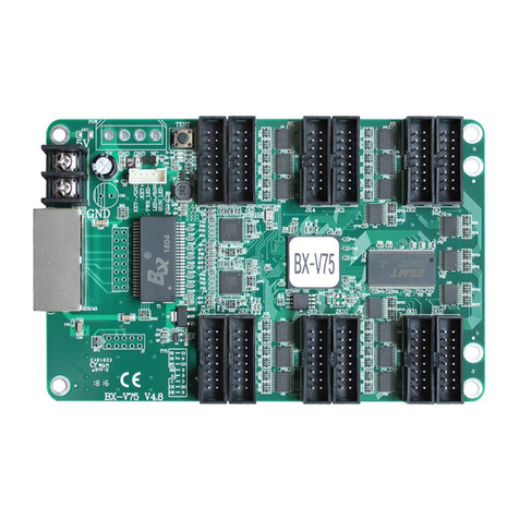
Onbon
Onbon BX-V75 user manual

BARIX
BARIX Barionet HANDS-ON TRAINING GUIDE
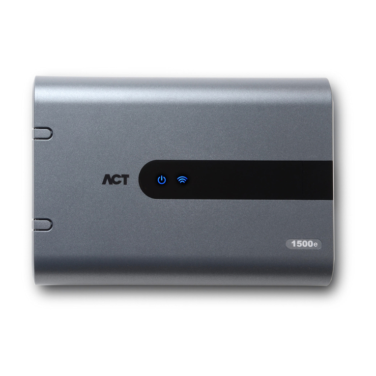
ACT
ACT ACTpro 1520e Operating and installation instructions
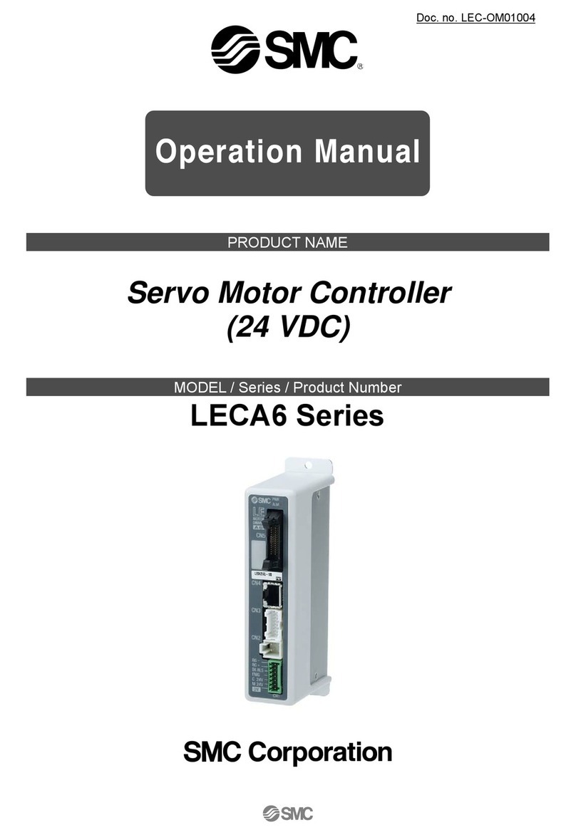
SMC Corporation
SMC Corporation LECA6 Series Operation manual

Mitsubishi Electric
Mitsubishi Electric MELSEC iQ-R Series user manual
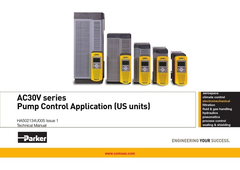
Parker
Parker AC30V Series Technical manual
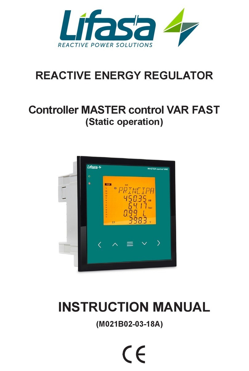
Lifasa
Lifasa MASTER control Var instruction manual


