manuals.online logo
Brands
  1. Home
  2. •
  3. Brands
  4. •
  5. Sistemes Electronics Progres
  6. •
  7. Controllers
  8. •
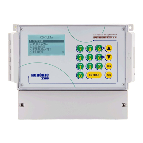
  9. Sistemes Electronics Progres Agronic 2500 User manual

Sistemes Electronics Progres Agronic 2500 User manual

SUPPLIED MATERIAL
BOX FORMAT ASSEMBLY
Installation option SDI-12 + 4
analogue inputs
Agrónic 2500
Disconnect power from the
controller.
1Remove the four screws that
hold the keyboard.
2
Remove the three inner
bars on the right side of the
drawer with a chisel/file, as
shown in the image.
5
Unscrew and remove the two
plates from the controller.
3
Make two holes in the box as
shown in the image using the
attached template.
4
Diameter
13 mm
64 mm
77 mm
23 mm
41 mm
Use a template to make the
holes. If the holes are not made
exactly as they should be, the
components will not fit.
IMPORTANT
SDI-12
board and
4 analogue
inputs
Terminal
Adhesive labels
Two SHR
screws
Cable 4 interior
analogue inputs
Interior SDI-
12 cable
Exterior SDI-
12 cable
Cable 4 exterior
analogue inputs
Board link cables
• Interior SDI-12 cable
• Exterior SDI-12 cable
• Cable 4 interior
analogue inputs
• Cable 4 exterior
analogue inputs
• SDI-12 board and 4
analogue inputs
• Terminal
• Board link cables
• Two SHR screws
• Adhesive labels
• Template for holes
Pass the SDI-12 cable through the
hole closest to the bottom of the
box. The straight sides should be
parallel to the bottom of the box.
6IMPORTANT: On the inside,
the black notch should be
parallel to the bottom of the
box.
7
Assemble the SDI-12 board
and four analogue inputs with
the two SHR screws.
11
Replace the base plate and its five
screws back in the controller.
8
It is recommended to fasten the
inner notches with a little glue
to prevent them from moving
when screwed on the outside.
10
Pass the second cable
following the same indications
as the first.
Connect the other side of the link
board cable to the keyboard board.
Connect the coloured cables
to the terminal as shown in the
image:
9
13
14
Connect the board link
cable to the SDI-12 board
and 4 analogue inputs.
12
Connect the terminal to the SDI-
12 board and 4 analogue inputs.
Close the controller by refitting
the four screws removed at point 2.
16
17
Reconnect the cables
between the two boards.
15
If the Plus option is not
showing on the controller, it must
be activated. If all steps have
been completed, the installation
is complete. Finally, configure the
controller referring to the A-2500
Plus manual and the SDI-12 option
manual.
18
R-2369
RECESSED FORMAT ASSEMBLY
For the recessed format, follow the same steps as the box format, changing points 4 and 11 to:
Break the die with a gentle
strike using a screwdriver or
similar.
Assemble the SDI-12 board
and four analogue inputs
with the two SHR screws.
4 11
Put insulating tape on the sheet,
between the drawer and the plate.
Bend the ground cable terminal of the
SDI-12 board and four analogue inputs
so that it is in contact with the drawer.
IMPORTANT

SDI-12 hole template + four
analogue inputs
Agrónic 2500
RIGHT SIDE
Box window
Top
Bottom
Hole diameter
13 mm
41 mm
23 mm
77 mm
64 mm
Box bottom
R-2369
Polígon Industrial, C/ de la Coma, 2 | 25243 El Palau d’Anglesola | Lleida | España
Tel. 973 32 04 29 | [email protected] | www.progres.es
Sistemes Electrònics Progrés, S.A.

Other Sistemes Electronics Progres Controllers manuals

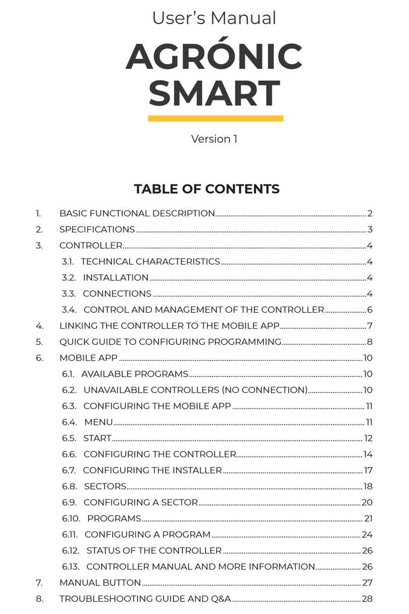
Sistemes Electronics Progres Agronic Smart User manual

Sistemes Electronics Progres

Sistemes Electronics Progres Agronic Smart User manual

Sistemes Electronics Progres Agronic 2500 User manual

Sistemes Electronics Progres

Sistemes Electronics Progres Agronic 2500 User manual

Popular Controllers manuals by other brands

Davey SolarMatic Installation and operating instructions

Davey

Davey SolarMatic Installation and operating instructions

IAI RCM-P First step guide

IAI

IAI RCM-P First step guide

Air Torque Upgrade Series Installation maintenance and operating instructions

Air Torque

Air Torque Upgrade Series Installation maintenance and operating instructions

ECUE DMX2CC Series Setup manual

ECUE

ECUE DMX2CC Series Setup manual

Berker 9450 01 00 Operation and assembly instructions

Berker

Berker 9450 01 00 Operation and assembly instructions

Ledj VersiMove 24 user manual

Ledj

Ledj VersiMove 24 user manual

Ei Electronics Ei450 instruction manual

Ei Electronics

Ei Electronics Ei450 instruction manual

Sanyo Denki Sanmotion R 3E S instruction manual

Sanyo Denki

Sanyo Denki Sanmotion R 3E S instruction manual

Mitsubishi Electric FX3GC user manual

Mitsubishi Electric

Mitsubishi Electric FX3GC user manual

RPE DIG Series Programming instruction manual

RPE

RPE DIG Series Programming instruction manual

PRESONUS FaderPort 16 owner's manual

PRESONUS

PRESONUS FaderPort 16 owner's manual

Omron F3SP-U4P-TGR datasheet

Omron

Omron F3SP-U4P-TGR datasheet

FSIP FS Series Instruction & installation manual

FSIP

FSIP FS Series Instruction & installation manual

HUST Automation HUST H2PN Operation manual

HUST Automation

HUST Automation HUST H2PN Operation manual

pitsco Tetrix Max User & Technical Guide

pitsco

pitsco Tetrix Max User & Technical Guide

Omron C200HS Series Replacement guide

Omron

Omron C200HS Series Replacement guide

Freescale Semiconductor MPC5604B Reference manual

Freescale Semiconductor

Freescale Semiconductor MPC5604B Reference manual

Siemens LMV37.4 Series Basic documentation

Siemens

Siemens LMV37.4 Series Basic documentation

manuals.online logo
manuals.online logoBrands
  • About & Mission
  • Contact us
  • Privacy Policy
  • Terms and Conditions

Copyright 2025 Manuals.Online. All Rights Reserved.