Sisu Commercial Products Sleeptight 1500SD Manual
Sleeptight 1500SD
Rev B – Sept. 2019
OWNER’S MANUAL AND INSTRUCTIONS
COMMERCIAL PRODUCTS
5009709

Sisu Commercial Products, LLC (“Manufacturer”) warrants its products (“the Products”) to be
free from defects in material and workmanship. Manufacturer’s Sleeptight Products shall be
warranted for a period of 12 months from the date of shipment.
Buyer’s sole and exclusive remedy for any nonconformity with this warranty shall be, at
Manufacturer’s option, repair or replacement of nonconforming parts, provided that Buyer
shall return to Manufacturer, shipping prepaid, said non-conforming part(s) bearing a
durable tag indicating the Serial Number of the Product from which the part was taken.
In addition, Manufacturer may opt not to repair or replace nonconforming Product or
part(s), but instead may refund to Buyer the price thereof, in lieu of repair or replacement.
In no event shall Manufacturer be liable for more than a refund of the purchase price or
replacement value of the Product or part(s), whichever is less. This Warranty does not apply
to eld labor charges.
This Warranty does not apply and shall be void as to any Products that are misused or
misapplied, that are installed, operated or maintained not in conformity with Manufacturer’s
design, specications, instructions, or Owner’s Manual, or are installed, operated or
maintained in violation of any applicable national or local codes or industry standards.
Manufacturer does not warrant Products, if they are abused, improperly operated or
maintained, subjected to abnormal wear and tear, damaged due to improper gas or electric
service, damaged in transit, or that have been repaired or modied by others without
Manufacturer’s written authorization.
Buyer shall have no right to enforce this Warranty unless it has complied with all of its
obligations under the contract for purchase/lease of the Products, including without
limitation, being current on all payment terms.
THIS LIMITED WARRANTY IS MANUFACTURER’S ONLY WARRANTY WITH RESPECT TO THE
PRODUCTS, AND IT IS IN LIEU OF AND SUPERSEDES ANY AND ALL OTHER WARRANTIES OF
ANY KIND WHATSOEVER, WHETHER WRITTEN, ORAL OR IMPLIED, INCLUDING WITHOUT
LIMITATION ANY IMPLIED WARRANTIES OF MERCHANTABILITY OR FITNESS FOR A
PARTICULAR PURPOSE. THE REMEDIES AFFORDED BUYER BY THIS WARRANTY ARE THE
ONLY REMEDIES AFFORDED BUYER FOR ANY NONCONFORMITY WITH THIS WARRANTY
OR FOR ANY DEFECT IN PRODUCTS, SERVICES, OR REPRESENTATIONS PROVIDED
BY MANUFACTURER IN CONNECTION WITH SUCH PRODUCTS. IN NO EVENT SHALL
MANUFACTURER BEAR ANY LIABILITY FOR INCIDENTAL OR CONSEQUENTIAL DAMAGES OF
ANY KIND WHATSOEVER, INCLUDING WITHOUT LIMITATION PERSONAL INJURY (INCLUDING
DEATH), PROPERTY DAMAGE, LOST PROFITS OR OTHER ECONOMIC LOSS.
Buyer acknowledges that the foregoing warranty, limitations, and exclusions are a
reasonable allocation of commercial risks by and among sophisticated business entities
and are not subject to dispute as to their commercial reasonableness, fairness or ability to
satisfy the essential purposes of the parties’ transaction.
Sisu Commercial Products, LLC has a continuous product improvement program; it reserves
the right to change design and specications without notice.
LIMITED WARRANTY
1

2
General Hazards........................................................... 3
Hazard Summary ......................................................... 4
System Description ...................................................... 5
Minimum Clearance to Combustible Materials....... 5
Specications ............................................................... 5
Air Quality Warning ..................................................... 6
System Components.................................................... 7
Electrical Interface Locations...................................... 8
Operator Interface Location ....................................... 8
Usage Instructions ..................................................9-14
Gas Train and Electrical Components .................... 15
Control Components ........................................... 16-17
Fresh Air Module Wiring Diagram ........................... 18
Heater Wiring Diagrams............................................ 19
Replacements Parts & Service.................................. 19
Maintenance Instructions ......................................... 20
Ignition Board Troubleshooting............................... 21
TABLE OF CONTENTS

GENERAL HAZARD WARNING:
Failure to comply with the precautions
and instructions provided with this
heater can result in death, serious
bodily injury and property loss
or damage from hazards of re,
explosion, burn, asphyxiation, carbon
monoxide poisoning, and/or electrical
shock.
Only persons who can understand and
follow the instructions should use or
service this heater.
If you need assistance or heater
information such as an instruction
manual, label, etc. contact the
manufacturer.
WARNING:
Fire, burn, inhalation, and explosion
hazard. Keep solid combustibles,
such as building materials, paper,
or cardboard, a safe distance away
from the heater as recommended
by the instructions. Never use
the heater in spaces which do or
may contain volatile or airborne
combustibles, or products such as
gasoline, solvents, paint thinner, dust
particles or unknown chemicals.
FOR YOUR SAFETY:
The use and storage of gasoline or other ammable vapors and liquids in
the vicinity of this appliance is hazardous.
WARNING:
Not for home or recreational vehicle
use.
3
GENERAL HAZARDS
Hazard Identication – Warnings, Cautions and Notices appear in appropriate
sections throughout this Owner’s Manual. Read these carefully!
WARNING - Indicates a potentially hazardous situation which could
result in death or serious injury.
CAUTION - Indicates a potentially hazardous situation which may result
in minor or moderate injury. It may also be used to alert against unsafe
practices.
NOTICE - Indicates a potentially hazardous situation which, if not avoided,
could result in property damage.
WARNING:
Operation, service, and repair of this equipment could result in exposure
to electrical, mechanical or other potential safety hazards and should only
be performed by qualied personnel. Use extreme caution and observe
safety regulations at all times.
WARNING:
Any unauthorized modication of this equipment shall void warranty.
Additional Hazards – The following safety precautions apply to the operation and
maintenance of the equipment described by this Owner’s Manual.
HAZARD SUMMARY
4

AIR QUALITY WARNING
•Do not use this heater for heating human living quarters.
•Use of direct-red heaters in the construction environment can result in exposure to levels of CO,
CO2, and NO2 considered to be hazardous to health and potentially life threatening.
• Do not use in unventilated areas
•Know the signs of CO and CO2 poisoning
• Headaches, stinging eyes
• Dizziness, disorientation
•Diculty breathing, feels of being suocated
•Proper ventilation air exchange (OSHA 29 CFR 1926.57) to support combustion and maintain
•acceptable air quality shall be provided in accordance with OSHA 29 CFR Part 1926.154, ANSI
•A10.10 Safety Requirements for Temporary and Portable Space Heating Devices and
•Equipment used in the Construction Industry or the Natural Gas and Propane Installation
• Codes CSA B149.1
•Periodically monitor levels of CO, CO2 and NO2 existing at the construction site – at
the minimum at the start of the shift and after 4 hours.
•Provide ventilation air exchange, either natural or mechanical, as required to maintain accept-
able indoor air quality.
WARNING
Air Quality Hazard
•Ensure that the ow of combustion and ventilation air exchange cannot become obstructed.
• As the building ‘tightens up’ during the construction phases ventilation may need to be
• increased.
HIGH ALTITUDE USE
Installation or use of this appliance at altitudes above 2000 ft (610 m) shall be in accordance with
local codes, or in the absence of local codes, the National Fuel Gas Code, ANSI Z223.1/NFPA
54, or National Standard of Canada, Natural Gas and Propane Installation Code, CSA B149.1.
USA 8-Hr Time weighted average Canada 8-hr time weighted average
(OSHA 29 CFR 1926.55 App A) WorkSafe BC OHS Guidelines Part 5.1
and Ontario Workplaces Reg 833
CO 50 ppm CO 25 ppm
CO2 5000 ppm CO25000 ppm
NO2NO23 ppm (Reg 833)
USA-Ceiling Limit
(Short Term Exposure Limit=15 minutes)
Canada STEL (15 minutes Reg 833/1 hour WSBC) WorkSafe BC
OSH Guidelines Part 5.1 and Ontario Worksplaces Reg 883
CO CO 100 ppm
CO2CO215000 ppm (WSBC)
30000 ppm (Reg 833)
NO25 ppm NO21.0 ppm (WorkSafeBC)
5.0 ppm (Reg 833)
5

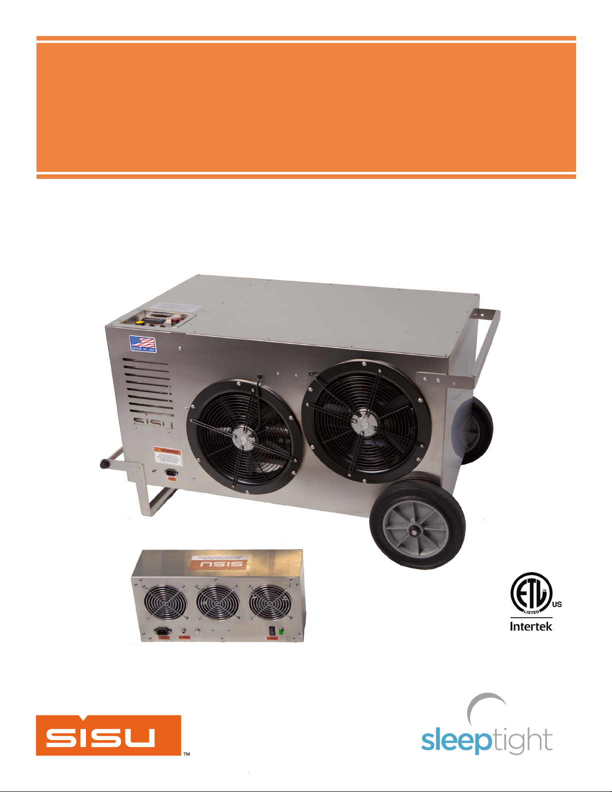
The Sleeptight 1500SD, patent pending, is designed for indoor use only. It is intended
for use in providing portable, temporary heat to buildings under construction,
alteration or repair. Adequate ventilation must be provided while heater is operating.
Combustible solids, such as building materials, paper or cardboard must be kept
at the minimum distance from the heater as shown in the table below. Never use
this heater in spaces which do or may contain volatile or airborne combustibles,
or products such as gasoline, solvents, paint thinner, dust particles or unknown
chemicals. Adequate building relief must be provided so as to not over pressurize the
building when this heater is operating at its rated capacity.
Gases: Propane
Capacity: 140,000 Btu/Hr maximum
Blower: 3000 CFM at 0.5”wc total static pressure
Electrical: 115V, 60Hz, 1Ph, 6.3Amps
Min Amb Temp: 32 Degrees F
Max Amb Temp: 140 Degrees F
Min Gas Supply Press: 14” wc
Max Gas Supply Press: 2 psi
Weight: 198 lbs
SYSTEM DESCRIPTION
SPECIFICATIONS
ETL certified to ANSI Z83.7-2017 Gas-Fired Construction Heater
6
MINIMUM CLEARANCE TO COMBUSTIBLE MATERIALS
Top 24 inches
Bottom 0 inches
Outlet side 36 inches
Inlet Side 24 inches
Front/Back 12 inches
5009709

SYSTEM COMPONENTS
Heater Unit
LP Gas Hose Assembly
Fresh Air Fan Module
3-way LP Tank Manifold
7
Interconnect Cable
Unit shown in upright transport and storage position
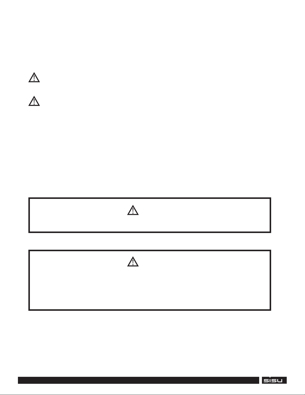
Electrical Interface Locations
21
Operator Interface Location
ITEM DESCRIPTION
1 INTERCONNECT CABLE SOCKET
2 POWER ENTRY RECEPTACLE
8

USAGE INSTRUCTIONS
Visual Inspection and Placement
a. Check for any physical damage from shipping, storage, or installation that could
render heater unsafe or inoperable.
b. Locate heater on level ground near the target area and observe and obey all
minimum safe distances of the heater to the nearest combustible materials. (Heater
must be kept away from combustible solids, such as building materials, bedding,
walls, paper or cardboard a minimum distance as shown on Page 5, reproduced
below.
c. Fresh air fan module installation
i. The Fresh Air Module can be installed in an exterior door frame, or external
window opening.
ii. If securing the Fresh Air Fan Module to an exterior window, the module must
securely be attached in a manner that prevents the module from falling outside.
WARNING: Fresh Air Fan Module may fall out of the window if not securely
fastened to the window frame.
9
Unit shown in operating position
Top 24 inches
Bottom 0 inches
Outlet side 36 inches
Inlet Side 24 inches
Front/Back 12 inches
WARNING: Fresh air fan module must be installed to supply a continuous
stream of fresh ventilation air into the area being heated at all times during
heater operation. Failure to comply can result in death or serious bodily injury
from hazards of asphyxiation or carbon monoxide poisoning.
WARNING: For indoor use only. Adequate ventilation shall be provided in
accordance with OSHA 29 CFR 1926.154, Safety Requirements for Temporary and
Portable Space Heating Devices and Equipment, ANSI A10.10, National Fuel Gas Code,
ANSI Z223.1/NFPA 54, Liqueed Petroleum Gas Code, NFPA 58 or the Natural Gas and
Propane Installation Code, CAN B149.1, as applicable.as Co
a. Ensure all manual shut-o valves on the gas hose and LP tank manifold are in the
closed position. Verify the connections of all the gas ttings are tight.
b. A minimum of two (2) 20 lb LP cylinders manifolded together, or one (1) 100 lb LP
tank is required to operate heater. Storage, handling and use of propane must be
in accordance with all local codes and ordinances, as well as NFPA 58 and OSHA
regulations.
WARNING: Supply cylinders must be designed, fabricated, tested and marked
in accordance with regulations of the U.S. Department of Transportation, Canadian
Transport Commission or the Interstate Commerce Commission, and must be
arranged to provide for vapor withdrawal from the operating cylinder(s).
WARNING: Connection to Liquid Propane gas (LP) cylinder(s) must conform
with local codes or, in their absence, with the Standard for the Storage and
Handling of Liqueed Petroleum Gases, ANSI/NFPA 58 or the Natural Gas and
Propane Installation Code, CSA B149.1, as applicable.
c. Connect the LP cylinder(s) to the provided tank manifold/regulator assembly and
connect the provided gas hose assembly between the regulator and the heater gas
train by utilizing the supplied ½” quick connect ttings.
Gas Connection
USAGE INSTRUCTIONS
10

USAGE INSTRUCTIONS
WARNING: The tank manifold/regulator assembly and gas hose assembly
must be visually inspected prior to each use of the heater. If there is evidence of
excessive abrasion or wear, or any hose is cut, it must be replaced prior to the
heater being put into operation.
WARNING: The heater must be located at least 10 feet from any propane gas
container. The heater’s discharge air shall not be directed toward any propane gas
container within 20 feet. Do not store propane in the space where the heater is to
be operated.
WARNING: The gas supply hose assembly must be protected from trac,
building materials and contact with hot surfaces both during use and while in
storage.
d. Slowly open all the gas supply manual valve(s) and allow pressure to equalize.
e. Check all pipe connections, hose connections, manual valves, ttings, and adapters
upstream of the heater’s electronic gas control valve for gas leaks using approved
gas leak detectors. In the event a gas leak is detected, check the components
involved for cleanliness and further tighten as necessary to stop the leak. Do not
proceed until all leaks are eliminated.
WARNING: All gas leaks detected must be repaired before heater is placed
into service.
Electrical Connection
a. Plug the Interconnect Cable into the fresh air fan module and the heater.
b. Plug the electrical power cord into the Fresh Air Fan Module and Heater. Plug both
into a properly grounded 115V 60Hz outlet (15A or greater).
WARNING: This appliance is equipped with a three-prong (grounding) plug
for your protection against shock hazard and should be plugged directly into a
properly grounded three-prong receptacle.
11

USAGE INSTRUCTIONS
Heater Start-Up
a. Turn the fresh air fan module’s POWER switch to the “ON” position. The fresh air
fans will begin to run.
b. Turn the heater POWER switch to the “ON” position and the circulating fans will
begin to run. The CO monitor will begin its initialization cycle and the alarm will
sound for several minutes until the system is operational.
c. Press the RESET button to enable the burner ignition system. The yellow Reset
Light and Low Gas Pressure Light will go o.
d. Turn the BURNER ENABLE switch to the “ON” positon to allow the burner to re.
e. Heater will attempt ignition after a 30 second pre-purge cycle.
NOTE: It is normal for air to be trapped in the gas hose upon each initial startup.
The heater may require more than one trial for ignition before air is nally purged
from line and ignition takes place.
f. Adjust the digital operating thermostat to the desired room temperature using the
“up” and “down” arrows. See detailed thermostat operating instructions below.
12
i. Press and release SET. The current value of the temperature set point SP1 is
displayed. SP1 and led OUT1 blink.
ii. Press UP or DOWN to increase or decrease the value.
iii. Press SET to conrm the new value. The current value of temperature set point
SP2 is displayed. SP2 and led OUT2 blink.
iv. Press UP or DOWN to increase or decrease the value. Press SET to conrm the
new value and exit.
NOTE: Only SP1 is utilized at this time. SP1 may only be set between 120 and 140
degrees F. OUT1 led energizes when thermostat SP1 is satised. The on/o set
point dierential is 2 degrees F.
USAGE INSTRUCTIONS
Heater Shut-Down
a. Close the LP cylinder valve(s) and allow the heater to burn o any fuel gas
remaining in the gas supply hose.
b. Turn the BURNER ENABLE switch to the “OFF” position.
c. Allow the heater circulating fan to continue to run for several minutes to cool the
heater.
d. Turn the heater POWER switch to the “OFF” position.
e. Close the remaining manual shut-o valve(s) and disconnect the gas supply piping
from the heater’s external connection. Plug all gas supply inlets to prevent the
entry of debris.
f. Turn the fresh air fan module’s POWER switch to the “OFF” position.
g. Unplug the power cord from the wall outlet and both the Fresh Air fan Module and
Heater.
h. Unplug the Interconnect Cable Fresh Air fan Module and Heater. Remove fresh air
fan module return door or window to its normal position.
i. When the heater is stored indoors, the connection between the propane supply
cylinder(s) and the heater must be disconnected and the cylinder(s) removed
from the heater and stored in accordance with the Standard for the Storage and
Handling of Liqueed Petroleum Gases, ANSI/NFPA 58 or the Natural Gas and
Propane Installation Code, CSA B149.1, as applicable.
WARNING: The gas supply hose assembly must be protected from trac,
building materials and contact with hot surfaces both during use and while in
storage.
13
Heater Shut-Down

1. Power on the Fresh Air Fan Module. Fresh air fans run.
2. Power on the heater unit. Circulating fan runs.
3. Press the RESET button and turn on BURNER ENABLE switch on the heater unit.
4. Thermostat closes on call for heat providing 24 VAC to Ignition Control.
5. Draft Inducer is energized (@ line voltage).
6. Air Switch closes initiating pre-purge period.
7. At end of pre-purge period, Spark and Gas Valve are energized for an ignition trial
period.
8. Burners ignite and carryover.
9. Flame is detected by ame sensor and control operates in steady state heating
condition.
10.Burners continue to re until the thermostat is satised.
11.Thermostat opens interrupting power to control and closes fuel valve to stop ring.
12.The unit enters its post-purge period.
13.If ignition is not achieved within the trial period, the gas valve is shut o; the inducer
continues to run for a 30 second inter-purge period. Additional ignition trials follow
the specied sequence. If all trials (3) for ignition have occurred without proper
ignition and ame detection, the control locks out. See ash codes on Page 20.
14.Control may be brought out of lockout by cycling the BURNER ENABLE switch or
shutting o power for a minimum of 5 seconds.
15.If ame is lost once it has been established, the control will shut o the gas
supply within 2.0 seconds and enter the inter-purge period. Control will allow a
predetermined number of ame losses before lockout. (To restart, refer to step 13)
16.If ame sensor indicates presence of ame during purge period, when no ame
should be present, the inducer will remain energized, but the gas valve will remain
o until the cause of the “false ame” is removed.
14
Sequence of Operation Overview
USAGE INSTRUCTIONS
15
3
5
6
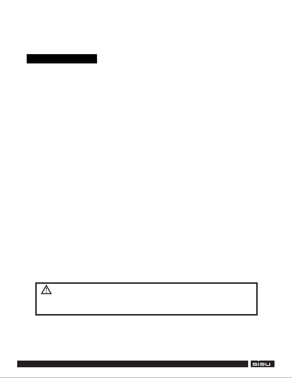
GAS TRAIN COMPONENTS
4
ITEM DESCRIPTION
3 GAS SHUT OFF VALVE
4 GAS PRESSURE SWITCH
5 APPLIANCE GAS REGULATOR
6 MALE QUICK CONNECT- 1/2” NPT
CO MONITOR
R1
TSH1
TILT
T2 T1
R2
12VDC SUPPLY
120VAC BUS
L N G L N G
L
N
GND
V-
V+
F-1
2A FUSE
297 SERIES
CONTROLS COMPONENTS
16
8
13
11
10
9
7
23
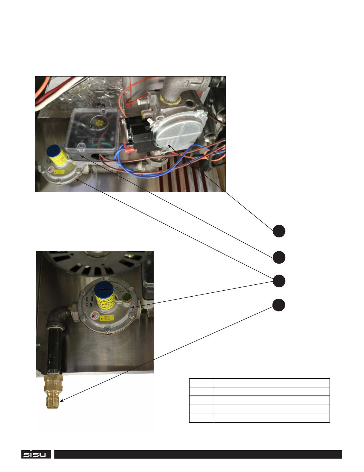
Operator Interface (Top of Heater)
Control Panel
15 12
14
22
21
20
16
17
ITEM DESCRIPTION ITEM DESCRIPTION
7 Digital Thermostat 16 Inlet Temperature Switch
8 CO Alarm Indicator 17 Tilt Switch
9 Power Switch 18 Manual Reset Relay
10 Burner Enable Switch 19 Low Fuel Pressure Relay
11 Heater Reset Button 20 CO Monitor
12 Circuit Breaker 21 Power Terminal Block
13 Power Indicator 22 Power Supply
14 Low Fuel Pressure Indicator 23 Fuse Holder
15 Reset Required Indicator
18
19
24 29
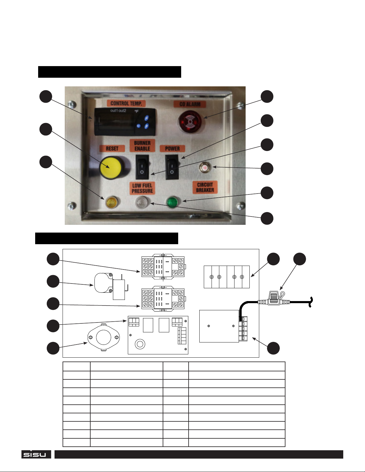
FRESH AIR MODULE WIRING DIAGRAM
17
ITEM DESCRIPTION ITEM DESCRIPTION
24 POWER ENTRY RECEPTACLE 27 FRESH AIR FANS
25 INTERCONNECT CABLE SOCKET 28 POWER SWITCH
26 CIRCUIT BREAKER 29 POWER INDICATOR
282725 26
Fresh Air Module Interface
CONTROLS COMPONENTS
18
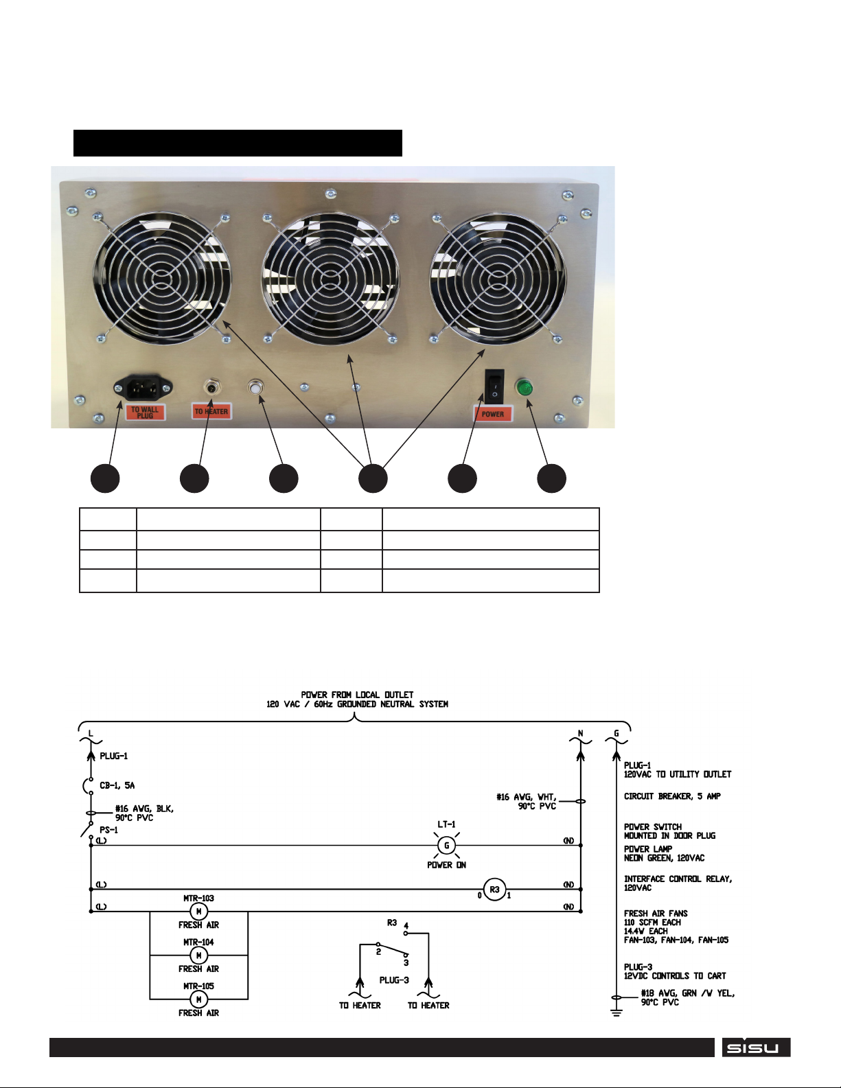
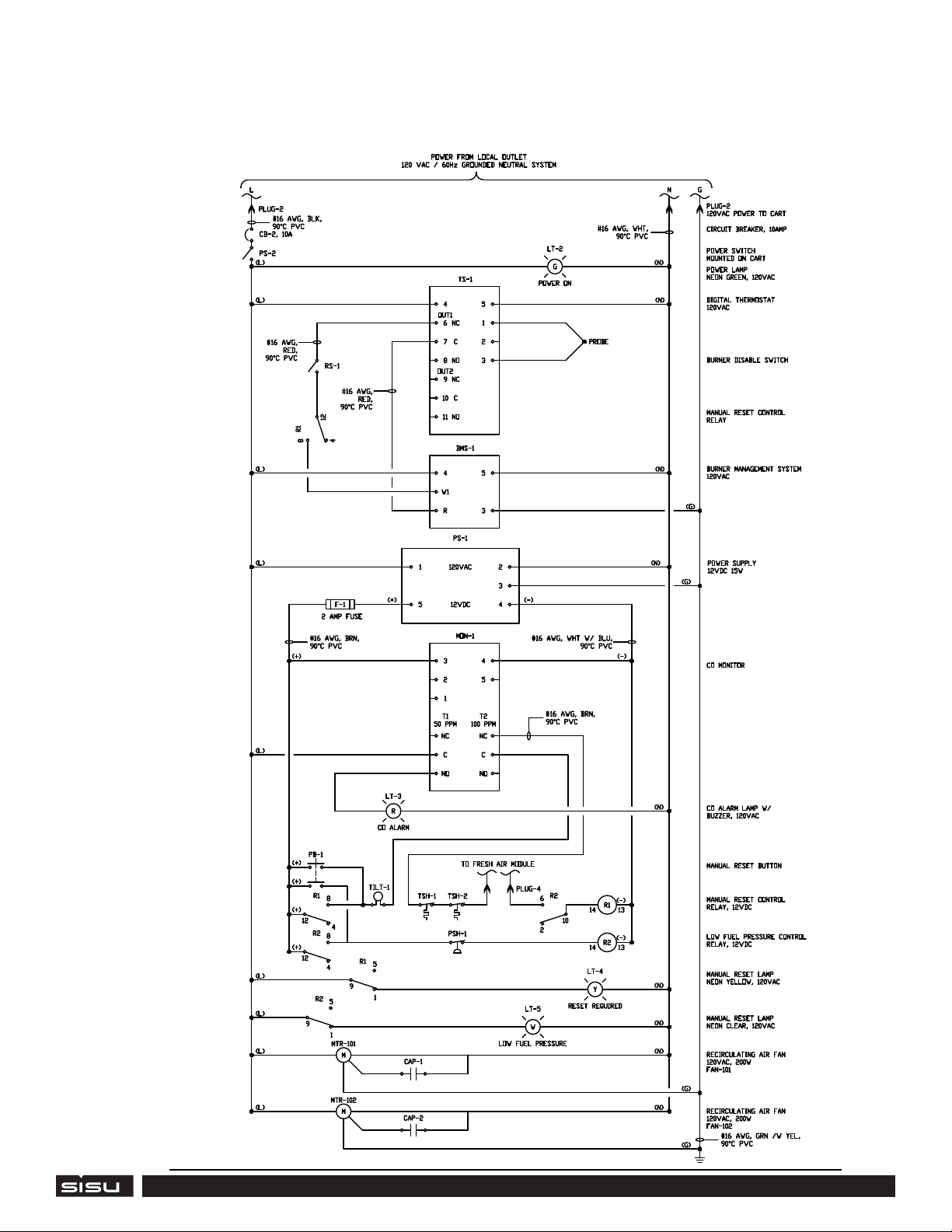
HEATER WIRING DIAGRAM
COMMERCIAL PRODUCTS
WIRING DIAGRAM

REPLACEMENT PARTS
19
P/N Location Description
21-003 Fresh Air Module Power Switch - Rocker Switch, Non Illuminated, SPST, On-O, Black, Panel, 20 A
21-014 Fresh Air Module Fresh Air Fan - Axial Fan, Terminal, Ball, 4715FS Series, 115 VAC, 119 mm, 38 mm, 110 cu.ft/min
21-027 Fresh Air Module Thermal Circuit Breaker, W57 Series, 250 VAC, 50 VDC, 5 A, 1 Pole, Panel
21-100 Fresh Air Module Indicator, Pnl-Mnt; Neon; Green; 0.500 In.; 105-125VAC; High Hat; 0.187 Terminals
04-200 Heater Axial Fan 398 dia. x 98.3 mm
19-002 Heater 2nd Stage LP Gas Regulator
19-010 Heater 1st Stage LP Gas Regulator
19-018 Heater Low gas pressure switch
21-001 Heater Alarm indicator
21-002 Heater Digital Operating Thermostat
21-003 Heater Power Switch - Rocker Switch, Non Illuminated, SPST, On-O, Black, Panel, 20 A
21-005 Heater 12VDC Power Supply
21-006 Heater CO Monitor
21-011 Heater 12VDC Fuse - Automotive Fuse, MINI 297 Series, 2 A, Fast Acting, 32 V, 10.9mm x 3.8mm x 8.8mm
21-013 Heater PTC Sensor for Operating Thermostat
21-016 Heater 15ft 16AWG Power Cord Cable w/ 3 Conductor PC Power Connector Socket (C13/5-15P) - Black
21-027 Heater Thermal Circuit Breaker, W57 Series, 5 A, 1 Pole, 50 VDC, 250 VAC, Panel
21-100 Heater Indicator, Pnl-Mnt; Neon; Green; 0.500 In.; 105-125VAC; High Hat; 0.187 Terminals
21-101 Heater Indicator, Pnl-Mnt; Neon; Amber; 0.500 In.; 105-125VAC; High Hat; 0.187 Terminals
21-104 Heater Indicator, Pnl-Mnt; Neon; Clear; 0.500 In; 105-125 VAC; Lens, High Hat; 0.187 Terminals
21-105 Heater Idec Relay, RH3B-U-DC12V
21-108 Heater Tilt Switch
21-109 Heater Recirculating Air Inlet Temperature Switch - 3L01-165
21-110 Heater Recirculating Air Outlet Temperature Switch - 3L01-300
21-111 Heater Fan Capacitor
Table of contents
Other Sisu Commercial Products Heater manuals


Popular Heater manuals by other brands


EUROM
EUROM E-Convect LCD in-control 351538 instruction manual

Dimplex
Dimplex DuoHeat Duo300i operating instructions

nedis
nedis HTOI30WT7 quick start guide

Russell Hobbs
Russell Hobbs RH09C Instructions and warranty

L.B. White
L.B. White GUARDIAN Smart Sense AD250 Owner's manual and instructions

wallas
wallas 270 Installation, operation and service instructions