Sisu Diesel 645 Series Instruction manual

WORKSHOP MANUAL
SISUDIESEL 645
8368 41000

Sisudiesel
645
engine
Workshop Manual
02 02
Sisu Diesel Inc.
FIN–37240 Nokia, Finland
Telephone: +358 3 341 7111
E–mail: info.sisudiesel@sisudiesel.com
www.sisudiesel.com
Diesel Engines, After Sales
Telefax: +358 3 341 7333
Sisu Diesel Inc. takes no responsibility for any damages caused
because of incorrect information in this manual

Contents 0 --- 0
CONTENTS
TO THE USER 0 --- 1.........................................................................
Engine type designations 0---1..........................................................
Location of the engine serial no. 0---2....................................................
Lifting the engine 0 --- 2.................................................................
SAFETY INSTRUCTIONS 0 --- 3................................................................
SPECIAL TOOLS 0 --- 4.......................................................................
ENGINE SPECIFICATION 0 --- 6................................................................
TECHNICAL DATA 0 --- 7......................................................................
Cylinder block 0 --- 7...................................................................
Cylinder liner 0 --- 7.....................................................................
Cylinder head 0 --- 7....................................................................
Valves, rocker arms and tappets 0--- 8....................................................
Camshaft 0 --- 8........................................................................
Crankshaft 0 --- 9.......................................................................
Flywheel 0 --- 9........................................................................
Timing gears 0 --- 1 0.....................................................................
Connecting rod 0 --- 1 0..................................................................
Piston, piston rings and pin 0---11........................................................
Lubricating system 0 --- 1 1................................................................
Oil pump 0 --- 1 1........................................................................
Coolant pump 0 --- 1 2....................................................................
Thermostat 0 --- 1 2......................................................................
Turbocharger 0 --- 1 2....................................................................
TIGHTENING TORQUES 0 --- 1 3................................................................
CONSTRUCTION 0 --- 1 4.......................................................................
General 0 --- 1 4.........................................................................
Cylinder block 0 --- 1 4...................................................................
Flywheel housing 0 --- 1 4.................................................................
Cylinder head 0 --- 1 5....................................................................
Valve mechanism 0 --- 1 5.................................................................
Crank mechanism 0 --- 1 5................................................................
Timing gears 0 --- 1 6.....................................................................
Lubricating system 0 --- 1 7................................................................
Cooling system 0 --- 1 8..................................................................
Inlet and exhaust system 0---19..........................................................
WORK INSTRUCTIONS
1. CYLINDER BLOCK
A. Measuring cylinder liner wear 1---1....................................................
B. Removing cylinder liner 1---1.........................................................
C. Checking cylinder block 1--- 1.........................................................
D. Changing camshaft bushing 1---1.....................................................
E. Fitting plug at camshaft rear end 1---2.................................................
F. Oversize bushings for camshaft 1--- 3..................................................
G. Fitting plug at camshaft rear end (oversize bushings) 1---3................................
H. Fitting cylinder liner 1---4.............................................................
2. FLYWHEEL HOUSING
A. Fitting flywheel housing 2---1.........................................................
B. Changing crankshaft rear oil seal 2---1.................................................
3. CYLINDER HEAD
A. Removing cylinder head 3---1........................................................
B. Removing valves 3 --- 1...............................................................
C. Checking cylinder head 3---1.........................................................
D. Changing valve guides 3---2..........................................................
E. Machining valve seat 3---2...........................................................
F. C h a n g i n g v a l v e s e a t r i n g 3 --- 3........................................................
G. Grinding valves 3 --- 3................................................................
H. Fitting valves 3 --- 3..................................................................
I. Fitting cylinder head 3---4............................................................
4. VALVE MECHANISM
A. Reconditioning valve mechanism 4---1.................................................
B. Changing camshaft/camshaft gear 4---1................................................
C. Adjusting valves 4 --- 2...............................................................

Contents 0 --- 0
5. CRANKSHAFT
A. Removing crankshaft 5---1...........................................................
B. Checking crankshaft 5---1............................................................
C. Changing crankshaft gears 5---1......................................................
D. Fitting crankshaft 5 --- 2...............................................................
E. Checking vibration damper 5---2......................................................
6. CONNECTING RODS AND PISTONS
A. Removing pistons together with connecting rods 6---1....................................
B. Changing connecting rod bearings 6---1...............................................
C. Checking connecting rod 6---1........................................................
D. Changing piston rings 6---3..........................................................
E. Checking pistons 6 --- 3..............................................................
F. Fitting piston pin 6 --- 4...............................................................
G. Fitting piston together with connecting rod 6--- 4.........................................
7. FLYWHEEL
A. Changing starter ring gear on flywheel 7---1............................................
B. Fitting flywheel 7 --- 1.................................................................
8. TIMING GEAR ASSEMBLY
A. Removing timing gear casing 8---1....................................................
B. Fitting timing gear casing 8---1........................................................
9. TENSIONING DEVICE
A. Tensioning device for ribbed belt 9---1.................................................
B. Fan drive device 9 --- 1...............................................................
10. LUBRICATION SYSTEM
A. Reconditioning of oil relief valve for lubricating oil pressure 10---1...........................
B. Removing and dismantling lubricating oil pump 10---1.....................................
C. Assembling and fitting lubricating oil pump 10---2.........................................
D. Fitting oil sump gasket 10--- 2..........................................................
E. Piston cooling nozzles 10---2..........................................................
E. Oil cooler 1 0 --- 3.....................................................................
G. Lubrication oil quality requirements 10--- 4...............................................
11. COOLING SYSTEM
A. Quality requirements of coolant 11---1..................................................
B. Thermostat 1 1 --- 1....................................................................
C. Reconditioning coolant pump 11---2....................................................
12. INLET--- AND EXHAUST SYSTEM
A. Checking air cleaner 12---1............................................................
B. Checking inlet and exhaust pipes 12---1.................................................
C. Checking turbocharger 12--- 1.........................................................
D. Fitting turbocharger 12--- 2............................................................
E. Fitting intercooler 1 2 --- 3..............................................................
13. FUEL SYSTEM
IN---LINE FUEL INJECTION PUMP
Technical data 1 3 --- 1...................................................................
A. Bleeding fuel system 13---6...........................................................
B. Bleeding thermostart system 13---6.....................................................
C. Measuring fuel feed pressure 13--- 7....................................................
D. Checking overflow valve 13---7........................................................
E. Changing fuel feed pump valves 13 ---7.................................................
F. Checking injection timing 13---7........................................................
G. Adjusting fuel injection timing 13---9....................................................
H. Adjusting idling speed 13--- 9..........................................................
I. Removing fuel injection pump 13---9....................................................
J. Fitting fuel injection pump 13---10.......................................................
K . R e m o v i n g i n j e c t o r s 1 3 --- 1 0.............................................................
L . I n s p e c ti n g i n j e c t o r s 1 3 --- 1 0.............................................................
M. Reconditioning injectors 13---11.........................................................
N. Fitting injector in engine 13---12.........................................................
O. Fitting delivery pipes 13---12............................................................
Fuel quality requirement 13---13...........................................................
14. EQUIPMENT AND FEEDING TABLES
15. ELECTRICAL SYSTEM
A. Alternators 1 5 --- 1....................................................................
B. Starters 1 5 --- 5.......................................................................
C. Fitting stop solenoid 15--- 8............................................................
D. Installation of magnetic pick up 15---8...................................................
E. Temperature sensor 15---8............................................................

645 DSB
A
EL
Application
A = vehicle engine
G= generating set engine
L = combine harvester engine
M= marine engine
P=pumpsetengine
Equipped with intercooler
A=airtoair
I = air to water
Equipped with Bosch P---type injection pump
Turbocharged engine (W, if equipped with by---pass turbo)
Basic type (E, if equipped with electronic engine control)
Number of cylinders
E = emission tested engine (certified) for off---road
C= emission tested engine (certified) for on---road
To t h e U s e r 0 --- 1
TO THE USER
This workshop Manual for Sisudiesel 645---diesel engines is intended to facilitate workshop operations and repair work.
645--- engines are mainly the same in construction, so the same repair instructions usually apply to different engine versions. The
differences between the various engine versions which affect repair work have been mentioned in technical data and repair in-
structions. All measurements are in millimetres and valid when the temperature of the parts is +20˚C, unless otherwise stated.
Before starting the repair work read the safety instructions in the beginning of this book. Make sure that you have all necessary
tools, parts and accessories at your disposal. The special tools mentioned in the work instructions are not all essential, but they
speed up and facilitate the work and contribute to successful execution of work. An engine which has undergone repairs must
be run in just like a new one.
Should the engine require measures not described in this manual, please consult your local agent or the Service Department of
Sisu Diesel Inc., Linnavuori, Finland. To facilitate consulting, find out the following facts about the engine before contacting us:
--- e n g i n e t y p e
--- engine number
--- application or equipment
--- hours operated or kilometres driven.
In this Workshop Manual the regular service procedure is not handled as this is explained in the 645---engines Operator’s Manual.
As Sisu Diesel Inc. is continuously developing the products, all rights are reserved without separate notice to change the adjust-
ments, accessories and service--- and repair procedure.
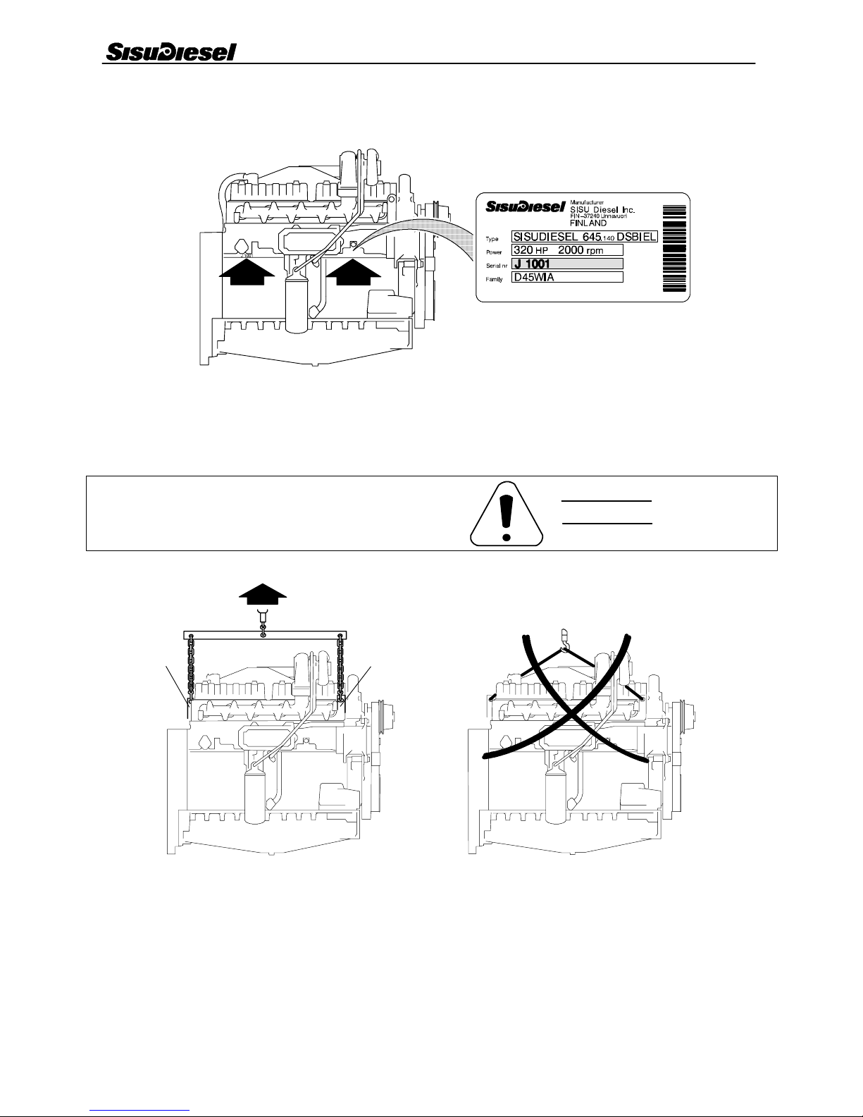
Engine type designations
WARNING
4 0 --- 2
AA
To t h e U s e r 0 --- 2
Location of the engine serial no.
4 0 --- 1
Lifting the engine
Safe lifting of the engine is done with a lifting device
where the lifting force effects the lifting ears vertically.
A= Engine lifting ears
Engine weight (dry, without flywheel and electrical equipment).
--- self carrying and casted oil sump 826 kg
--- normal oil sump 690 kg

Safety Instructions 0 --- 3
SAFETY INSTRUCTIONS
In the service--- and repair work of the engine there is al-
ways the possibility of injury. Before starting the work
read and understand the following safety instructions
and remarks!
Do not start a repair work that you do not fully handle.
Make sure that the place of the repair and the surround-
ing gives the possibility for safe working.
Always be sure of the cleanness and the good order of
the repairing place.
Do not use faulty or otherwise useless tools.
Remove all finger rings, chains and watch before start-
ing work.
Use up ---todate protection equipment when you work.
For example eye protection as working with compressed air
for cleaning, grinding, hammering or other work.
Use lifting device for lifting and transporting heavy (over
20 kg) pieces. make sure of good condition of lifting hooks
and chains. The lifting ears on the engine must not be applied
by side forces when lifting.
Never work under an engine that is left handling under
a lifting device or lifted up by a jack. Always use strong sup-
ports before starting the work.
Use only genuine Sisudiesel spare parts.
Start the engine only by using the starting switch in the
cabin.
Do not start an engine if the protection covers are re-
moved. NOTE! The fan is difficult to see as the engine is run-
ning! Make sure that wide clothes or long hear is not caught
in the rotating parts of the engine.
If you start the engine indoors, be sure you have proper
ventilation.
Never use aerosol type of starting aid while operating
the thermostart device (risk for explosion).
When you are operating the engine or working near it,
use hearing protectors to avoid noise injuries.
Stoptheenginealwaysbeforeservice---orrepairwork.
Avoid touching the exhaust manifold, turbocharger and
the other hot parts of the engine.
Open the radiator cap with care when the engine is hot
as the cooling system is pressurised. The cooling liquid and
lubrication oil of a hot engine causes injuries when touching
the skin.
Open fire, smoking and sparks should not be allowed
near the fuel system and batteries. (Specially when loading
batteries, explosive.)
Always disconnect the minus (---) wire of the battery
when doing service or repair of the electric system.
At temperatures on excess of 300˚C, e.g. if the engine
is burnt by a fire, the viton seals of the engine (e.g. the under-
most o--- ring of the oil pressure regulating valve) produce
very highly corrosive hydrofluoric acid. Do not touch with bare
hands, viton seals subjected to abnormally high tempera-
tures. Always use neoprene rubber or heavy duty gloves and
safety glasses when decontaminating. Wash the seals and
the contaminated area with a 10% calcium hydroxide or other
alkali solution. Put all removed material in sealed plastic bags
and deliver them to the point stated by the Authorities con-
cerned. NOTE! Never destroy viton--- seals by burning!
When checking fuel injectors do not let the jet of high
pressure fuel contact your skin. The fuel penetrates the skin
causing severe injuries. Contact your doctor immediately!
The fuel, lubricating oil and coolant cause irritation in
skin contact for long time.
Avoid unnecessary idling of the engine.
Do not let oil and other liquids drop into the soil when
servicing the engine.
All the gaskets of the engine are of non---asbestos ma-
terial.
Be careful when washing the engine with a high pres-
sure washing machine. Do not use high pressure to wash e.g.
the electric and fuel equipment or the radiator because they
can easily be damaged.

Special Tools 0 --- 4
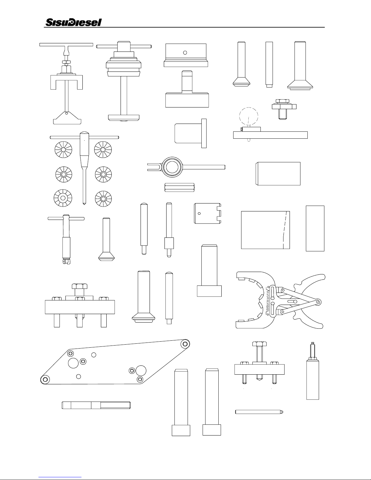
SPECIAL TOOLS
Order no Description
1 9104 51500 Puller for cylinder liner
2 9104 52000 Milling cutter for cylinder liner seat
3 9104 52700 Centring tool for flywheel housing
4 9104 52600 Drift for fitting rear crankshaft seal
5 9103 94600 Drift for fitting front crankshaft seal
6 9052 46620 Drift for 40 mm cup plug
7 9052 46650 Drift for 16 mm cup plug
8 9025 87400 Drift for fitting camshaft cup plug
9 9101 66300 Press tool for cylinder liner
10 9025 79200 Holder for dial gauge
11 9101 66100 T--- handle for valve seat milling cutter
12 9101 71100 Milling cutter for facing exhaust valve seat
13 9101 65502 Milling cutter for exhaust valve seat
14 9101 65503 Inner milling cutter for exhaust valve seat
15 9101 75800 Milling cutter for facing inlet valve seat
16 9101 65505 Milling cutter for inlet valve seat
17 9101 65506 Inner milling cutter for inlet valve seat
18 9101 66200 Lever for compressing valve spring
19 9052 47200 Counter nut for lever above
20 9101 66000 Milling tool for injector seat
21 9052 46660 Drift for 36 mm cup plug
22 9101 65800 Drift for removing valve guide
23 9101 65900 Drift for fitting valve guide
24 9024 55800 Spanner for crankshaft nut
25 9103 94700 Drift for fitting crankshaft gears
26 9103 41300 Drift for fitting coolant pump bearings
27 9105 18700 Conical sleeve for fitting pistons
28 9052 46900 Piston ring pliers
29 9103 94900 Drift for fitting oil deflector ring, crankshaft front end
30 9103 94800 Drift for 45 mm cup plug
31 9025 98700 Drift for fitting tension pins in timing gear casing and flywheel housing
32 9104 53300 Puller for crankshaft hub
33 9104 05400 Centring tool for idler gear, broad timing gear casing
34 9104 34600 Centring pin for idler gear, narrow timing gear casing
35 9103 41000 Fitting tool for coolant pump shaft seal
36 9103 41100 Fitting tool for coolant pump water seal
37 9052 48900 Extractor for injection pump gear
38 9104 52800 Injection timing check pin
39 9104 53700 Extractor for injector
Special Tools 0 --- 5
12
3
4
678
9
10
5
11
12
13
14
15
16
17
18
19
21 22 23
24
26
25
29
27
30 31
20
28
39
38
37
4 0 --- 3
32
33
34
35 36

Engine Specifications 0 --- 6
ENGINE SPECIFICATIONS
PRINCIPAL DIMENSIONS AND DATA
Motor type 645...................................................
Number of cylinders 6...........................................
Displacement (ltr) 8,4..............................................
Cylinder bore (mm) 111............................................
Stroke (mm) 145..................................................
Combustion Direct injection..................................................
Compression ratio 16/17:1.............................................
Injection timing (B.T.D.C.) Marked on the flywheel or damber.......................................
Valve clearance, intake and exhaust (mm) 0,35 (cold or hot).........................
Direction of rotation from the engine front Clockwise.........................
Compression pressure (bar)124....................................
1) Minimum value at operating temperature and starting revs. Max permitted difference
between cylinders 3,0 bar.
FUELSYSTEM
Injection pump Bosch, in --- line type................................................
Fuel Gas oil, see page 13--- 13.........................................................
Feed pressure
--- overflow valve opening pressure 0,6 ---1,0 bar...............................
--- static 2,7 bar......................................................
I n j e c t i o n o r d e r 1 --- 5 --- 3 --- 6 --- 2 --- 4................................................
Injector Four/five hole nozzle......................................................
Opening pressure of the nozzle See page 14--- 3..................................
Adjusting pressure of the nozzle See page 14--- 3.................................
Fuel filter CAV.....................................................
LUBRICATION SYSTEM
Oil pressure in hot engine at running speed 2,5---5,0 bar.......................
Oil pressure at idle speed, min. 1,0 bar..................................
Oil capacity (ltr) See page 10---4...............................................
COOLING SYSTEM
Numbers of thermostats 2........................................
Opening temperature ˚CÆ54 mm = 79 Æ67 mm = 83.......................................
Coolant liquid See page 11 --- 1.................................................

Technical Data 0 --- 7
TECHNICAL DATA
Cylinder block
Holes for guide pins 13,250...13,320 mm........................................................
Main bearing housing diameter 96,000...96,025 mm...............................................
Cylinder liner location, diameter:
--- u p p e r e n d 125,014...125,054 mm...............................................................
--- l o w e r e n d 121,000...121,040 mm...............................................................
Inner diameter of camshaft bushings (fitted) 50,010...50,070 mm....................................
Height of cylinder block 468,900...469,100 mm.....................................................
Cylinder liners
Protrusion of cylinder liner above cylinder block top face 0,030...0,080 mm..........................
Max. permissible height difference between liners (under same head) 0,02 mm..............
Outer diameter of cylinder liner guide:
--- at upper end of liner 124,975...125,000 mm......................................................
--- at lower end of liner 120,961...120,986 mm.......................................................
Liner bore 111,000...111,022 mm.................................................................
Height of cylinder liner flange 9,03...9,05 mm.................................................
Height of cylinder liner flange, 1st oversize, part no 8368 59581 9,08...9,10 mm....................
Height of cylinder liner flange, 2nd oversize, part no 8368 59582 9,13...9,15 mm...................
Height of cylinder liner flange, 3rd oversize, part no 8368 59583 9,23...9,25 mm...................
Outer diameter of cylinder liner flange 131,700...131,800 mm.........................................
Cylinder head
Height of cylinder head 104,800...105,000 mm......................................................
Height of cylinder head after repair grinding (minimum) 104,000 mm..........................
Inside diameter of valve guide (not fitted) 9,000...9,015 mm.......................................
Outside diameter of valve guide 16,028...16,039 mm..............................................
Diameter of valve guide bore in cylinder head 16,000...16,018 mm...................................
Position of valve guide top above cylinder head surface 21 mm..........................
Depth of valve head face below cylinder head surface:
--- i n l e t v a l v e 0,7±0,05 mm (max 2,20 mm)...............................................................
--- exhaust valve 0,6±0,05 mm (max 2,20 mm)............................................................
Angle of valve seat:
--- i n l e t v a l v e 35˚+20’
...............................................................
--- exhaust valve 45˚+20’
............................................................
Width of valve seat:
--- i n l e t v a l v e 2,9...3,7 mm...............................................................
--- exhaust valve 1,3...2,3 mm............................................................
Diameter of exhaust valve seat ring 44,070...44,132 mm............................................
Diameter of exhaust valve seat rings recess 44,000...44,025 mm.....................................
Diameter of exhaust valve seat ring (overhaul part 8366 52269) 44,270...44,332 mm....................
Diameter of exhaust valve seal ring recess (overhaul part 8366 52269) 44,200...44,225 mm..............
Diameter of inlet valve seat ring 48,570...48,632 mm...............................................
Diameter of inlet valve seat ring recess 48,500...48,525 mm.........................................
Diameter of inlet valve seat ring (overhaul part 8368 55347) 48,770...48,832 mm.......................
Diameter of inlet valve seat ring recess (overhaul part 8368 55347) 48,700...48,725 mm.................

Technical Data 0 --- 8
Valves, rockers and tappets
With a valve clearance of 1,0 mm:
--- i n l e t v a l v e o p e n s 0 ˚±2˚B.T.D.C.........................................................
--- i n l e t v a l v e c l o s e s 1 6 ˚±2˚A.B.D.C.........................................................
--- exhaust valve opens 39˚±2˚B.B.D.C......................................................
--- exhaust valve closes 1˚±2˚A.T.D.C......................................................
Valve clearance cold and hot:
--- i n l e t v a l v e 0,35 mm...............................................................
--- exhaust valve 0,35 mm............................................................
Angle of valve seat in cylinder head:
--- i n l e t v a l v e 35˚+20’
...............................................................
--- exhaust valve 45˚+20’
............................................................
Width of valve seat in cylinder head:
--- i n l e t v a l v e 2,9...3,7 mm...............................................................
--- exhaust valve 1,3...2,3 mm............................................................
Angle of valve face:
--- i n l e t v a l v e 35˚--- 2 0 ’
...............................................................
--- exhaust valve 45˚--- 2 0 ’
............................................................
Outside diameter of valve head:
--- i n l e t v a l v e 48 mm...............................................................
--- exhaust valve 41 mm............................................................
Max valve movement:
--- i n l e t v a l v e 10,9 mm...............................................................
--- exhaust valve 12,1 mm............................................................
Inlet valve stem diameter 8,960...8,975 mm....................................................
Exhaust valve stem diameter 8,925...8,940 mm.................................................
Inlet valve stem clearance 0,025...0,055 mm....................................................
--- R e j e c t l i m i t 0,30 mm..............................................................
Exhaust valve stem clearance 0,060...0,090 mm................................................
--- R e j e c t l i m i t 0,35 mm..............................................................
Inside diameter of valve guide before fitting 9,000...9,015 mm.....................................
Outside diameter of valve guide 16,028...16,039 mm..............................................
Diameter of valve guide bore in cylinder head 16,000...16,018 mm...................................
Protrusion of valve guide top above cylinder head surface 21 mm........................
Depth of valve face below cylinder head surface:
--- i n l e t v a l v e 0,7±0,05 mm (max 2,20 mm)...............................................................
--- exhaust valve 0,6±0,05 mm (max 2,20 mm)............................................................
Valvespringfreelength 69,8mm......................................................
Spring pressure when spring compressed to a length of:
--- 4 8 , 6 m m 327±17 N................................................................
--- 3 7 , 4 m m 500±23 N................................................................
Rocker arm shaft diameter 22,970...22,990...................................................
Diameter of rocker arm bore 23,000...23,021..................................................
Max. permissible push rod deflection (when free) 0,4 mm................................
Free length of rocker arm spring 80 mm..............................................
Spring pressure when spring compressed to a length 58 mm 80...100 N.....................
Outside diameter of tappet 29,939...29,960 mm...................................................
Diameter of tappet bore in cylinder block 30,000...30,043 mm.......................................
Camshaft
Diameter of camshaft bearing journal no 1 49,925...49,950 mm......................................
Diameter of camshaft bearing journals nos 2, 3 and 4 49,865...49,890 mm............................
Diameter of camshaft bearing journals no 5 49,885...49,910 mm.....................................
Inside diameter of camshaft bearing bushes (when fitted in position) 50,010...50,070 mm...............
Camshaft clearance in bearing bush no 1 0,060...0,145 mm......................................
Camshaft clearance in bearing bushes nos 2, 3 and 4 0,110...0,160 mm............................
Camshaft clearance in bearing bushes no 5 0,090...0,140 mm....................................
Bearing bush tolerance in block (press fit) 0,025...0,080 mm......................................

Technical Data 0 --- 9
Camshaft end play with 0,5 mm gasket between cylinder block and timing gear
housing and between timing gear housing and front cover 0,5...1,0 mm........................
Cam height (distance between back of cam and tip of cam):
--- i n l e t v a l v e 41,180...41,430 mm...............................................................
--- exhaust valve 40,080...40,330 mm............................................................
Cam lift:
--- i n l e t v a l v e 7,38 mm...............................................................
--- exhaust valve 8,28 mm............................................................
Camshaft max. permissible deflection (total indicator reading) 0,03 mm.....................
Crankshaft
Crankpin diameter:
--- s t a n d a r d 72,981...73,000 mm................................................................
--- 1. undersize 0,25 mm 72,731...72,750 mm.....................................................
--- 2. undersize 0,50 mm 72,481...72,500 mm.....................................................
--- 3. undersize 1,00 mm 71,981...72,000 mm.....................................................
--- 4. undersize 1,50 mm 71,481...71,500 mm.....................................................
Crankpin length 40,000...40,160 mm............................................................
Main bearing journal diameter:
--- s t a n d a r d 89,985...90,020 mm................................................................
--- 1st undersize 0,25 mm 89,735...89,770 mm....................................................
--- 2nd undersize 0,50mm 89,485...89,520 mm....................................................
--- 3rd undersize 1,00 mm 88,985...89,020 mm....................................................
--- 4th undersize 1,50 mm 88,485...88,520 mm....................................................
Main bearing housing diameter (in cylinder block) 96,000...96,025 mm...............................
Main bearing shell thickness:
--- s t a n d a r d 2,955...2,965 mm................................................................
--- 1st undersize 0,25 mm 3,080...3,090 mm....................................................
--- 2nd undersize 0,50 mm 3,205...3,215 mm....................................................
--- 3rd undersize 1,00 mm 3,455...3,465 mm....................................................
--- 4th undersize 1,50 mm 3,705...3,715 mm....................................................
Main bearing clearance 0,050...0,127 mm......................................................
Length of thrust bearing journal (journal nearest to flywheel):
--- standard (2 standard thrust plates) 45,000...45,080 mm..........................................
--- 1st oversize (one std and one 0,1 mm overthick thrust plate) 45,100...45,180 mm....................
--- 2nd oversize (one std and one 0,2 mm overthick thrust plate) 45,200...45,280 mm....................
--- 3rd oversize (one 0,1 mm and one 0,2 mm overthick thrust plate) 45,300...45,380 mm................
--- 4th oversize (two 0,2 mm overthick thrust plates) 45,400...45,480 mm..............................
Other crankshaft journals may not be ground longer.
Corner rounded of crankpins and journals R4+0,5 mm......................................
Crankshaft end float 0,100...0,380 mm.........................................................
Max. permissible ovalness and other deformity of crankpins or journals 0,03 mm.............
Crankshaft unbalance 1,0 Ncm Max........................................................
Flywheel
Interference fit between ring gear ---flywheel 0,425...0,600 mm.....................................
Before fitting the ring gear, heat up to a temperature of 150...200˚C...........................
Flywheel unbalance 1,0 Ncm Max.........................................................
Max permissible axial wobble of flywheel clutch face, measured at inner edge
of clutch face on diameter 200 0,06:ø200................................................

Technical Data 0 --- 1 0
Timing gears
Tooth backlash:
Crankshaft---idler gear 0,05...0,25 mm.......................................................
Idler gear ---camshaft gear 0,05...0,25 mm....................................................
Idler gear ---fuel injection pump gear 0,05...0,25 mm...........................................
Max. permissible side wobble of gears 0,05 mm.........................................
Idler gear shaft, diameter 49,995...50,011 mm....................................................
Inner diameter of idler gear bearing hole 89,955...89,990 mm.......................................
Camshaft gear hole diameter 32,000...32,025 mm.................................................
Camshaft end diameter 32,043...32,059 mm......................................................
Timing marks:
Timing marks on gears are in alignment when the 1st cylinder piston is at its top dead centre between
compression and power strokes.
On crankshaft gear 2 dots on tooth.........................................................
On idler gear:
--- against crankshaft gear mark 1 dot on tooth...............................................
--- against camshaft gear mark 1 dot on tooth................................................
--- against fuel injection pump gear mark 2 dots on notch.......................................
On camshaft gear 1 dot on notch..........................................................
On injection pump gear 1 dot on notch.....................................................
Connecting rod
Inside diameter of piston pin bush (with bush pressed into connecting rod) 44,025...44,040 mm..........
Outside diameter of piston pin bush (std) 48,080...48,120 mm.......................................
Outside diameter of piston pin bush (oversize 8363 38606) 48,580...48,620 mm........................
Interference fit: connecting rod small end bushing---connecting rod 0,057...0,120 mm................
Connecting rod small end bore 48,000...48,025 mm...............................................
Connecting rod small end bore (oversize bush) 48,500...48,525 mm.................................
Connecting rod big end bore 76,730...76,749 mm.................................................
Big end bearing shell thickness:
--- s t a n d a r d 1,833...1,842 mm................................................................
--- 1st undersize 0,25 mm 1,958...1,967 mm....................................................
--- 2nd undersize 0,50 mm 2,083...2,092 mm...................................................
--- 3rd undersize 1,00 mm 2,333...2,342 mm....................................................
--- 4th undersize 1,50 mm 2,583...2,592 mm....................................................
Big---end bearing clearance 0,046...0,102 mm..................................................
End float (side clearance) at big---end on crankshaft 0,200...0,312 mm.............................
Piston pin bushing location perpendicular to longitudinal axis of connecting
rod to be within 0,10:100............................................................
Piston pin bushing location and big---end bearing location to be parallel to within 0,05:100.....
Weight marking (letter) at lower end.
Max. permissible weight difference between connecting rods in the same engine 20 g.....
Position of connecting rod; weight marking at valve mechanism side
(away from the combustion chamber in the piston)

Technical Data 0 --- 1 1
Piston, rings and pin
Minimum distance between piston and cylinder head (measured with a piece
of lead wire thought the injector location hole) 0,900...1,150 mm....................................
Piston diameter:
--- 15 mm from lower edge 110,863...110,877 mm....................................................
Pin bore in piston 44,003...44,009 mm............................................................
Piston pin diameter 43,994...44,000 mm..........................................................
Width of ring grooves:
--- 1 s t g r o o v e wedge shaped ring................................................................
--- 2 n d g r o v e 2,520...2,540 mm................................................................
--- 3 r d g r o o v e 4,040...4,060 mm...............................................................
Side clearance of piston rings in their grooves:
--- 1 s t r i n g wedge shaped ring..................................................................
--- 2 n d r i n g 0,03...0,062 mm.................................................................
--- 3 r d r i n g 0,05...0,082 mm..................................................................
--- r e j e c t l i m i t 0,15 mm................................................................
Piston ring height (in direction of cylinder):
--- 1 s t r i n g wedge shaped ring..................................................................
--- 2 n d r i n g 2,478...2,490 mm.................................................................
--- 3 r d r i n g 3,975...3,990 mm..................................................................
Piston ring gap (with piston fitted in cylinder)
--- 1st ring (wedge shaped ring) 0,35...0,50 mm................................................
--- 2 n d r i n g 0,60...0,80 mm.................................................................
--- 3 r d r i n g 0,30...0,60..................................................................
--- reject limit 1. and 3. ring 1,0 mm....................................................
--- reject limit 2. ring 1,3 mm..........................................................
Max. permissible weight difference between pistons in same engine 25 g.................
Piston to be heated up to 100˚C before fitting gudgeon pin.
Piston position in cylinder: combustion chamber of piston to face towards injector.
Lubricating system
Oil pressure at normal running temperature:
--- at idling speed (min.) 1,0 bar......................................................
--- at running speed 2,5...5,0 bar..........................................................
Free length of oil pressure valve spring 71 mm.........................................
Spring pressure when valve spring is compressed to a length of 52 mm 74+5 N.............
Diameter of oil pressure valve plunger 19,602...19,635 mm..........................................
Diameter of oil pressure valve cylinder 19,700...19,752 mm..........................................
Oil filter by---pass valve opens at a pressure difference of 2±0,5 bar..........................
Oil pump
Backlash between gears when crankshaft lies firmly against the lower side of main bearings:
--- crankshaft gear---lubricating oil pump gear 0,05...0,25 mm....................................
--- between the pump gears 0,16...0,26 mm...................................................
Diameter of drive shaft at bearings for body and cover 17,966...17,984 mm............................
Diameter of drive shaft bearing hole on body and cover 18,000...18,018 mm...........................
Diameter of fixed shaft at gear wheel 17,966...17,984 mm...........................................
Inner diameter of bearing for gear wheel which rotates on fixed shaft 18,000...18,018 mm................
Fixed shaft in pump body, diameter 20,035...20,048 mm............................................
Protrusion of fixed shaft end below pump body face 0,5 mm..............................
Thickness of cover gasket 0,06...0,08 mm....................................................
Outer diameter of gear wheels 55,824...55,870 mm.................................................
Housing diameter 56,000...56,120 mm...........................................................
Thickness of gears 32,000...32,027 mm...........................................................
End play of gears 0,03...0,11 mm............................................................
Depth of housing 32,000...32,043 mm............................................................
Number of teeth on drive gears 46 pcs................................................

Technical Data 0 --- 1 2
Coolant pump
Outside diameter of bearing 52 mm..................................................
Inside diameter of bearing housing in pump body 51,970...52,000 mm...............................
Shaft diameter at bearing 24,996...25,009 mm....................................................
Shaft diameter at impeller 15,907...15,920 mm....................................................
Impeller hole diameter 15,881...15,899 mm.......................................................
Diameter of the water seal recess in the pump body 39,981...40,020 mm..............................
Thermostat
Spare part number Type Opening Fully Max. stroke
begins at open at mm
8360 15156 ø54/79˚C79˚±2˚C94˚C7,5
8363 31590 ø67/83˚C83˚±2˚C95˚C8
Turbocharger
Schwitzer S2B
Max. axial end play 0,14 mm.........................................................
Max. radial play1)0,95mm...........................................................
Turbine housing attaching bolts 17 Nm...............................................
Nut on end of shaft 15,6 Nm.........................................................
1) Measured at nut on end of shaft.
Schwitzer S300
Min. axial end play 0,05 mm..........................................................
Max. axial end play 0,12 mm.........................................................
Max. radial play, turbine end 0,64 mm.................................................
Max. radial play, compressor end 0,88 mm.............................................
Turbine housing attaching bolts 22 Nm...............................................
Compressor housing attaching bolts 13,5 Nm...........................................
Nut on end of shaft 20,3 Nm.........................................................
Tightening Torques 0 --- 1 3
TIGHTENING TORQUES
Object Nm
Cylinder head bolts 80 Nm +90˚+90˚( s e e p a g e 3 --- 4 ).......................................................
Cylinder head studs to cylinder block 30............................................
Main bearing bolts 200...........................................................
Connecting rod bolts seepage6---2......................................................
Crankshaft nut 1000..............................................................
Oil pump gear nut 60............................................................
Crankshaft pulley bolts 80........................................................
Flywheel bolts 200...............................................................
Flywheel housing bolts:
--- outer ring M12 110............................................................
--- i n n e r r i n g M 1 0 60..............................................................
Belt tightener shafts bolts:
--- M 1 0 80......................................................................
--- M 1 6 200.....................................................................
Idler gears retaining bolts:
--- the bigger bolt (M14) 180.......................................................
--- the bolts for holding the bearing (M8) 22..........................................
Piston cooling valve 30...........................................................
Oil pump retaining bolts 60.......................................................
Coolant pump gear nut 180.......................................................
Exhaust manifold nuts 50.........................................................
Intake manifold bolts 30..........................................................
Injection pump gear nut 200......................................................
Injector attaching nuts (on studs) 15................................................
Injector nozzle sleeve 60..........................................................
Always use the torque values listed in the following tables when specific torque values are not available.
M8 M10
Cast iron 35±5 Nm 70±5 Nm
Aluminium 25±5 Nm 50±5 Nm
Use a washer with the aluminium parts.
The bolts of a self carrying oil sump
1 M8 12.9 30 Nm
2 M10 12.9 90 Nm
3 M12 12.9 150 Nm
4 M16 10.9 300 Nm
5 M20 10.9 700 Nm
6 M22 10.9 700 Nm
4 0 --- 4
Construction 0 --- 1 4
CONSTRUCTION
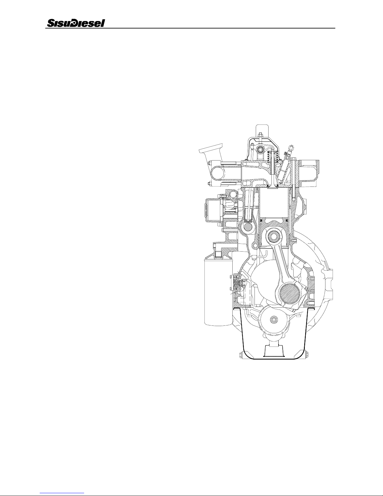
General
6 4 5 --- e n g i n e i s l i q u i d c o o l e d , 6 --- c y l i n d e r, 4 --- s t r o k e , i n --- l i n e
diesel engine with direct injection. It is designed with wet, re-
placeable, mid support cylinder liners, oil--- cooled pistons
and two separate cylinderheads.
The engines have a rigid and ribbed cylinder block. The crank
mechanism is designed for supercharging. The cylinder
liners are wet and supported at the middle. The cylinder head
bolts are high tensile bolts.
Cylinder block
The cylinder block is the main body of the engine, to which
other engine parts are attached. Wet and replaceable cylinder
liners are supported at the middle which reduces vibrations
and directs coolant circulation mainly to the upper part of the
liners.
The seal between the cylinder liner lower part and the cylinder
block is achieved by three o---rings, which are fitted in
grooves in the cylinder block. The upper part is sealed by the
cylinder head gasket.
The camshaft is located in the cylinder block. 645--- engines
have separate bearing sleeves in all camshaft bearing loca-
tions. The drilling for the camshaft rear end is covered with a
plug.
There are spaces on both sides of the rear main bearing for
guide bearing shims (the crankshaft thrust bearings).
Flywheel housing
The flywheel housing is fitted at the rear end of the cylinder
block. The seal for the crankshaft rear end is placed in a bore
in the housing. The starter motor fixing point is fitted in the fly-
wheel housing.
The lower face of the flywheel housing functions as a sealing
surface for the oil sump gasket. This means that the lower
face of the cylinder block must be level with the flywheel
housing. When fitting the flywheel housing, its position is
determined by tension pins.
The flywheel housing are delivered according to the require-
ments set, by the engine application and different flywheel
housings can be mounted on all engine types.

Construction 0 --- 1 5
4 0 --- 5
Cylinder head
645---engines have two cylinder heads which are exchange-
able with each other. Each cylinder has its own inlet and
exhaust ports located on either side of the head. Between hot
exhaust valves a cool inlet valve is fitted to balance the ther-
mal load.
Cylinder head bolts are high tensile bolts which are tightened
up to yield limit using angle tightening principle. Due to the
large stretch the tightening forces are kept constant during
the whole lifetime and retightening is unnecessary.
The injector locations are machined directly into the cylinder
head. The inlet and exhaust valve guides are identical and
can be interchanged. In addition, the inlet and exhaust valves
are equipped with replaceable valve seat inserts.
Valve mechanism
The valve mechanism is operated by the camshaft which is
located in the cylinder block. The drive is transferred with the
help of tappets and pushrods. The camshaft gear wheel is
fitted with a press fit and fixed with a key. Each bearing is lubri-
cated by the force feed lubrication system through drilled oil-
ways in the motor block.
Crank mechanism
The crankshaft is forged from chrome alloy special steel and
is induction hardened at the bearing and sealing surfaces.
This makes it possible to grind bearings four times without a
new heat treatment. Gear wheels are located at the front end
of the crankshaft. They are a press fit, and drive the idler
wheel and oil pump. In addition, the front end of the crank-
shaft has splines for the hub of the ribbed V --- belt pulley. An
oil deflector ring is fitted between the hub and gear wheel.
The crankshaft is supported on the cylinder block by main
bearings which are placed on both sides of each cylinder.
Thus there is one main bearing more than cylinders. The
crankshaft thrust washers are placed in both sides of the rear-
most main bearing.
At the rear end of the crankshaft there is fitted a flywheel on
which is a press---fit a starter ring gear. The forged connecting
rod has an I--- s e c t i o n c r o s s --- s e c t i o n . T h e b e a r i n g l o c a t i o n a t
the bottom end of the connecting rod is angle split, and the
bearing cup is secured by two special elongated bolts. The
upper part has a wedge---shaped bearing location, in which
the piston pin bearing bushing is fitted with a press fit.
The piston is made of an eutectic aluminium alloy. In the
upper face of the piston there is a combustion chamber. The
shape of the chamber is intended to maximise the mixture of
air and fuel. The piston has three rings. The upper molyb-
d e n u m --- c oa t e d r i n g h a s a w e d g e --- s h a p e d c r o ss --- s e c t i o n .
The middle ring is tapered and it fits into its groove. The taper
taking up the clearance. The oil control ring is spring loaded
and it has a two--- stage, chromed scraping edge.
The upper ring location is formed in a cast iron ring which is
cast in the piston. In addition, the piston is graphite coated to
ensure correct running--- in.
1
234
6
5
1
234
6
5
7
8
4 0 --- 6
Construction 0 --- 1 6
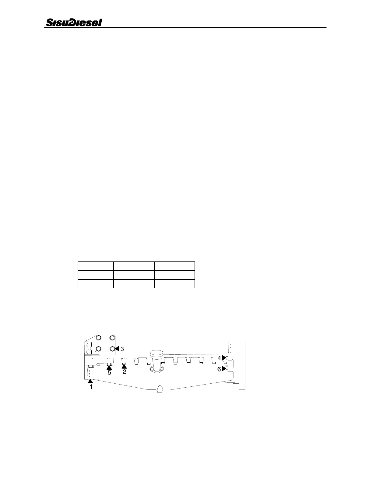
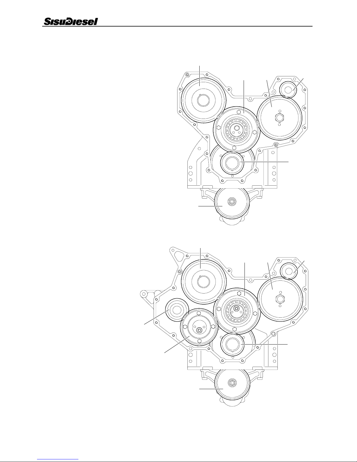
Timing gears
There are two main types of a timing gear assemblies, so---
called narrow--- and broad timing gear casing.
The timing gear train consists of hardened, helically cut gear
wheels. The gears are encased by the timing gear casing
which is fitted to the front of the engine. The timing gear drives
the camshaft, fuel injection pump, oil pump and coolant
pump.
If the engine is equipped with the broad timing gear casing,
there is a separate drive unit for a hydraulic pump or a com-
pressor. The drive unit is driven via a small idler gear.
The idler gear is supported with a bevelled ball bearing on the
shaft on the front face of the cylinder block.
Narrow timing gear casing
1. Camshaft gear
2. Idler gear
3. Injection pump gear
4. Coolant pump gear
5. Crankshaft gears
6. Oil pump gear
Broad timing gear casing
1. Camshaft gear
2. Idler gear
3. Injection pump gear
4. Coolant pump gear
5. Crankshaft gears
6. Oil pump gear
7. Small idler gear
8. P.T.O. gear
Table of contents
Other Sisu Diesel Engine manuals

Popular Engine manuals by other brands


Kohler
Kohler Courage XT-6 owner's manual

vario helicopter
vario helicopter Zenoah G230 operating instructions

ANTOR
ANTOR 3LD510 manual

RADEMACHER
RADEMACHER RolloTube DuoFern Brief instructions for installation and initial commissioning

FAAC
FAAC T-Mode TM 45 manual

Ametek
Ametek dunkermotoren BG 75 instruction manual