Ametek dunkermotoren BG 75 User manual

BG 75
Motor Part No.
75x25 88575.070XX
75x50 88575.080XX
75x75 88575.090XX
mit Anbau 88710.XXXXX
Instruction Manual
BLDC motor with
EtherCAT Interface
Betriebsanleitung
Bürstenloser DC - Motor mit
EtherCAT Schnittstelle
Dunkermotoren GmbH | Allmendstraße 11 | D-79848 Bonndorf/ Schwarzwald

2BG 75 EC www.dunkermotoren.de Version 06.2019
1 So arbeiten Sie optimal mit
dem Dokument 4
1.1 Dokument 4
1.2 Motorbaureihe BG 75 EC 5
1.3 Allgemeine Begriserklärungen 6
1.4 EtherCAT spezische Begrie 7
1.4.1 CANopen over EtherCAT 7
1.4.2 Servicedatenobjekt (SDO) 7
1.4.3 Prozessdatenbank (PDO) 8
1.5 Bestimmungsmäßige Verwendung 8
2 Grundlegende Sicherheitshinweise 9
3 Technische Daten 10
3.1 Mechanische Daten 10
3.2 Elektrische Daten 11
3.2.1 BG 75x25 EC 12
3.2.2 BG 75x50 EC 12
3.2.3 BG 75x75 EC 12
3.3 Maßzeichnung 13
3.4 Betriebsarten 13
3.4.1 Dunkermotoren spezische
Ansteuerung „Quick-Start“ 13
3.4.2 Betriebsmodi nach CiA DS402
(EN 61800-7-201:2008) 14
3.4.3 TwinCATSystem 15
3.4.4 File Access over EtherCAT (FoE) 15
3.4.5 Nicht unterstützte Funktionen 15
3.5 Zertikate/ Konformitäten 15
4 Zubehör 16
4.1 EtherCAT Starter Kit 16
4.1.1 ESI-Datei 16
4.1.2 Beispiele 16
4.1.3 Dokumentationen 16
4.2 Optionale Anbauten 17
5 Schutzfunktionen 18
5.1 Energierückspeisung 18
5.2 Übertemperaturschutz 18
5.3 Strombegrenzung 19
5.4 Ballastschaltung 19
6 Installation 20
6.1 Mechanische Installation 20
6.1.1 Winkellage Motorstecker
Leistungsversorgung 20
6.2 Elektrische Installation 21
6.2.1 Elektromagnetische
Verträglichkeit 21
6.2.2 Erdung 21
1 The best way of using
the document 4
1.1 Document 4
1.2 Motor series BG 75 EC 5
1.3 General explanations 6
1.4 EtherCAT specic explanations 7
1.4.1 CANopen over EtherCAT 7
1.4.2 Service Data Object (SDO) 7
1.4.3 Process Data Object (PDO) 8
1.5 Proper use 8
2 Safety instructions 9
3 Technical data 10
3.1 Mechanische Daten 10
3.2 Elektrische Daten 11
3.2.1 BG 75x25 EC 12
3.2.2 BG 75x25 EC 12
3.2.3 BG 75x25 EC 12
3.3 Motor installation drawing 13
3.4 Operating modes 13
3.4.1 Dunkermotor specic
control „Quick-Start“ 13
3.4.2 Operation modes according to CiA
DS402 (EN 61800-7-201:2008) 14
3.4.3 TwinCAT System 15
3.4.4 File Access over EtherCAT (FoE) 15
3.4.5 Non supported functions 15
3.5 Certicates/ Conformities 15
4 Accessories 16
4.1 EtherCAT Starter Kit 16
4.1.1 ESI-File 16
4.1.2 Examples 16
4.1.3 Documentation 16
4.2 Optional attachments 17
5 Protective functions 18
5.1 Regenerative current 18
5.2 Over-temperature protection 18
5.3 Current limitation 19
5.4 Ballast Circuit 19
6 Installation 20
6.1 Mechanical Installation 20
6.1.1 Angle adjustment motor connector
power supply 20
6.2 Electrical Installation 21
6.2.1 Electro-magnetic
compatibility 21
6.2.2 Ground wire 21

3
Version 06.2019 www.dunkermotoren.com BG 75 EC
6.2.3 Leistungsversorgung Motor 22
6.2.4 Gegenstecker mit Anschluss-
leitung Leistungsversorgung Motor 22
6.2.5 Elektronikversorgung und
Signalschnittstelle 23
6.2.6 Gegenstecker mit Anschlußleitung
für Elektronikversorgung und
Signalschnittstelle 23
6.2.7 Maximale Kabellängen und
Spannungsversorgung 25
6.2.8 EtherCAT Anbindung
(Pinbelegung) 27
6.2.9 Serviceschnittstelle 28
6.2.10 Prinzipschaltbild Spannungs-
versorgung BG75 EC 29
7 Inbetriebnahme 30
7.1 Vorbereitung 30
7.2 Status LEDs 30
8 EtherCAT-Master 32
8.1 Allgemein 32
8.2 Beispiel Beckho 32
9 Wartung & Service 33
9.1 Wartung, Ausserbetriebsetzung
und Entsorgung 33
9.2 Service & Support 34
9.3 Lieferumfang und Zubehör 34
9.4 Download PDF-Daten 34
6.2.3 Power supply Motor 22
6.2.4 Mating connector with connection
cables for power supply motor 22
6.2.5 Power supply electronic and signal
interface 23
6.2.6 Mating connector with connection
cables for supply electronic and
signal interface 23
6.2.7 Maximum cable length and
power supply 25
6.2.8 EtherCAT connector
(Pin assignment) 27
6.2.9 Service interface 28
6.2.10 Schematic circuit power supply
BG75 EC 29
7 Commissioning 30
7.1 Preparation 30
7.2 Status LEDs 30
8 EtherCAT-Master 32
7.1 General 32
7.2 Example Beckho 32
9 Maintenance & Service 33
8.1 Maintenance, taking out of service
and disposal 33
8.2 Service & Support 34
8.3 Scope of delivery and accessories 34
8.4 Download PDF-Data 34

4BG 75 EC www.dunkermotoren.de Version 06.2019
1 So arbeiten Sie optimal mit
dem Dokument
1.1 Dokument
Die vorliegende Betriebsanleitung stellt Ihnen den
bürstenlosen DC- Servomotor mit EtherCAT-
Schnittstelle vor und informiert Sie über alle
Schritte zur Installation der Antriebe und zur
Durchführung erste Funktionstests.
Weiterführende Informationen zu EtherCAT nden
Sie auch auf der Internetseite www.ethercat.org.
Lesen und befolgen Sie in diesem
Dokument die Warnhinweise
sorgfältig. Die Warnhinweise sollen
Sie vor Gefahr schützen oder helfen
Ihnen, eine Beschädigung des
Gerätes zu vermeiden.
HINWEIS
Read and observe the warnings in this
dokument. Warnings are there
to protect you from danger, and to
help you to avoid damage to
the device.
NOTICE
Hinweise erläutern Ihnen Vorteile
bestimmter Einstellungen und helfen
Ihnen, den optimalen Nutzen aus dem
Gerät zu ziehen.
HINWEIS
Instructions explain the advantages of
certain settings and help you use the
devicetothebestpossibleeect.
NOTICE
Vor der Inbetriebnahme sind unbe-
dingt die Sicherheitshinweise zu lesen
und zu beachten! Eine Nichtbeach-
tung kann zu Gefahren bei Personen
oder Beschädigungen an der
Maschine führen.
►Gerät spannungsfrei
schalten !
WARNUNG
Before commissioning, it is
essential that the safety instructions
in the relevant section are read and
understood, and then observed!
Non-observance can result in danger
to persons or damage to the machine.
►Disconnecttheelectricalpower
supply!
WARNING
1 The best way of using the
document
1.1 Document
These operating instructions introduce you to the
brushless DC- motor with EtherCAT interface and in-
form you about all necessary steps for installation and
carrying out initial functional tests.
You nd further information about EtherCAT on the
hompage www.ethercat.org.

5
Version 06.2019 www.dunkermotoren.com BG 75 EC
1.2 Motorbaureihe BG 75 EC
• Bürstenloser DC-Servomotor mit integriertem
Motioncontroller, integriertem Rotorlagegeber und
EtherCAT Schnittstelle.
• Diesen Antrieb zeichnet eine hohe Dynamik, die
kompakte Bauweise, der große Regelbereich,
sein geringes Trägheitsmoment und der robuste
Aufbau aus.
• Integrierter Inkrementalgeber mit einer Auösung
von 4096 (4x 1024) Inkrementen pro Umdrehung.
Dadurch werden eine hohe Positioniergenauigkeit
und sehr gute Regeleigenschaften erreicht.
• Wesentliche Parameter einer Trajektorie wie
Positions-, Geschwindigkeits- und Beschleuni-
gungswerte können über die EtherCAT-
schnittstelle verändert werden.
• Der Motor hat außer den Kugellagern keine
Verschleißteile und eignet sich deshalb
hervorragend auch für Dauerbetrieb.
• Die Motoren BG 75 EC können auf Wunsch auch
mit Planeten-, oder Schneckengetrieben mit einer
Vielzahl fein abgestimmter Untersetzungen kom-
biniert werden.
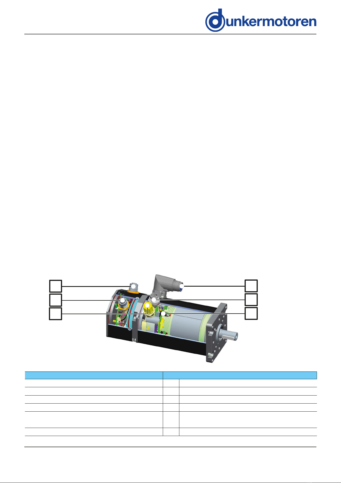
Description Pos. Bezeichnung
EtherCAT in, Round plug M12, 4-pin (D-coded) AEtherCAT in, Rundstecker M12, 4-polig (D-codiert)
EtherCAT out, Round plug M12, 4-pin (D-coded) BEtherCAT out, Rundstecker M12, 4-polig (D-codiert)
Service interface, Round plug M12, 5-pin CService-Schnittstelle, Rundstecker M12, 5-polig
Power supply motor, Round plug M17, 4-pin DLeistungsversorgung, Rundstecker M17, 4-polig
Power supply electronic and signal interface,
Round plug M16, 12-pin EElektronikversorgung und Signalschnittstelle,
Rundstecker M16, 12-polig
Motion controller integrated FIntegrierter Motioncontroller
1.2 Motor series BG 75 EC
• Brushless DC - servo-motors with integrated
motion controller, integrated rotor-position sensor
and EtherCAT interface.
• A signicant advantage of this drive is the highly
dynamic performance, the compact design, the
wide regulation range, the low moment of inertia,
and robust construction.
• By means of the integrated incremental encoder
with a resolution 4096 (4x 1024) increments
per revolution, a very high positioning accuracy
with very good regulating characteristics can be
achieved.
• The most important parameters of a trajectory,
such as position, speed, and acceleration settings
can be changed via EtherCAT interface.
• The motor is excellent suitable for continuous ope-
ration because only the ball bearings of the
motor are wear parts.
• The motors BG 75 EC can be combined with
planetary or worm gears with a multitude of ne
tuned gear ratios.
AD
B
C
E
F

6BG 75 EC www.dunkermotoren.de Version 06.2019
1.3AllgemeineBegriserklärungen
Begri Erklärung
Baud Rate Übertragungs-/ Kommunikati-
onsgeschwindigkeit
Bus
Ein Bus ist ein System zur
Datenübertragung zwischen
mehreren Teilnehmern über
ein gemeinsames Übertra-
gungsmedium
Current/ Torque
Mode
Strom bzw. Drehmoment-
regelung
Defaultwerte Voreingestellte Werte
Hallsensoren Sensor zur Positions-
bestimmung des Rotors
Kommutierung
Kommutierung bezeichnet in
der Leistungselektronik den
Übergang des Stromusses
von einer Motorphase in die
Nächste.
Motion controller Motorsteuerung
Position Mode Positionierregelung
SVEL Mode
Drehzahlregelung für überge-
ordnete Positioniersysteme,
z.B. CNC-Steuerungen.
Trajektorie Bewegungsablauf
Velocity Mode Drehzahlregelung
1.3 General explanations
Term Explanation
Baud rate Speed of transmission or
communication
Bus
A bus system transmits data
between multiple users over
a common medium
Commutation
Commutation in power
electronics describes the
transition of current ow from
one motor phase to the next.
Default settings Preset values
Hall sensors Sensors for determining the
position of the rotor
Motion controller Motor control
Position mode Regulation of position
SVEL Mode
Speed regulation for superor-
dinate positioning systems
(e.g. a CNC-control system).
Torque mode Current- respectively torque
mode
Trajectory Sequence of motions
Velocity mode Speed control

7
Version 06.2019 www.dunkermotoren.com BG 75 EC
1.4EtherCATspezischeBegrie
1.4.1 CANopen over EtherCAT (CoE)
EtherCAT stellt mit der Anwendungsschicht “CANopen
over EtherCAT (CoE)” die gleichen Kommunikati-
onsmechanismen bereit, wie sie von CANopen her
bekannt sind: Objektverzeichnis (Motorparameter),
PDO (Prozessdatenobjekte) und SDO (Servicedaten-
objekte). Selbst das Netzwerkmanagement ist ver-
gleichbar.
Bei bereits verwendeten Dunkermotoren mit CAN-
Bus Schnittstelle, sollte der Umstieg somit sehr leicht
fallen.
1.4.2 Servicedatenobjekt (SDO)
Die Servicedatenobjekte (SDO) bilden den Kommu-
nikationskanal für die Übertragung von Gerätepara-
metern. SDOs werden vor allem bei der Initialisierung
und zu Servicezwecken verwendet.
Im Antrieb müssen z.B. Strombegrenzungen, Regel-
parameter, Geberauösung und die zyklische Kom-
munikation (PDO) initialisiert werden.
SDOs werden azyklisch übertragen: Beim Hochfah-
ren des Netzes zur Initialisierung oder bei Bedarf zu
Servicezwecken.
Um ein Objekt im Antrieb zu beschreiben oder auszu-
lesen, wird die Objektadresse bei jedem SDO mitge-
schickt.
1.4EtherCATspecicexplanations
1.4.1 CANopen over EtherCAT (CoE)
EtherCAT provides with the application layer “CANo-
pen over EtherCAT (CoE)” the same communication
mechanisms as the familiar CANopen mechanisms:
object dictionary (drive parameters), PDO (process
data objects) and SDO (service data objects) - even
the network management is comparable.
If you already used Dunkermotoren with CAN-bus in-
terface, the transfer from CAN-Bus to CANopen over
EtherCAT should be very easy.
1.4.2 Service Data Object (SDO)
The Service Data Objects (SDO) are the communica-
tion channel for the transmission of device parame-
ters. SDOs are especially used for initialization and for
service purposes.
Following parameters have to be initialized: e.g.
current limitations, controller parameters, encoder
resolution and the cyclic communication (PDOs).
SDOs are transmitted acyclic: When you start up the
network for initialization or on demand for service
issues.
For writing or reading an object in the drive, the object
address is sent with each SDO.

8BG 75 EC www.dunkermotoren.de Version 06.2019
1.4.3 Prozessdatenobjekt (PDO)
Die Prozessdatenobjekte (PDO) dienen dem schnel-
len und ezienten Austausch von Echtzeitdaten
(z.B. E/A-Daten, Soll- oder Istwerte). Im EtherCAT-
Telegramm werden keine Objekte adressiert, sondern
direkt die Inhalte der Prozessdaten gesendet.
Hierfür muss zuvor festgelegt werden, welche Para-
meter per PDO beschrieben und gesendet werden
sollen (PDO Mapping). Das PDO Mapping muss somit
vorab per SDO initialisiert werden.
Hinweis für PDOs:
Die entsprechenden PDO-Mappings für den Motor
sind noch separat zu treen.
1.5 Bestimmungsmäßige Verwendung
- Der BG 75 EC ist ein Zulieferteil und darf in der
beschriebenen Konguration in Maschinen und
Anlagen eingesetzt werden (industrieller Bereich).
- Der Antrieb muss fest montiert werden und darf nur
mit den von Dunkermotoren spezizierten Kabeln
und Zubehörteilen eingesetzt werden.
- Der Antrieb darf erst nach EMV-gerechter Montage
des Gesamtsystems in Betrieb genommen werden.
1.4.3 Process Data Object (PDO)
The process data objects (PDO) provide fast and
ecient exchange of real-time data (e.g. I/O-Data, tar-
get and actual values). In the EtherCAT telegram no
objects are addressed, but the content is sent directly
to the process data.
So that data can be sent directly to the objects, the
objects have to be dened before (PDO Mapping).
The PDO Mapping has to be initialized with SDOs.
Advice for PDOs:
The appropriate PDO-Mappings for the motor are to
be adjusted separately.
1.5 Proper use
-The BG 75 EC is a vendor part and may be used
in the conguration described in machines and plant
(industrial sector).
- The drive must be securely mounted and must only
be used with the cables and accessories specied
by Dunkermotoren.
- The drive may only be put into service after the
complete system has been installed with due
attenti on to EMC aspects..

9
Version 06.2019 www.dunkermotoren.com BG 75 EC
2 Safety instructions 2 Grundlegende Sicherheitshinweise
Die Antriebe dürfen nur von
qualiziertem Personal nach den
entsprechenden Normen eingebaut
und eingerichtet werden.
Als qualiziert gilt eine Person dann:
►wennihreErfahrungmöglicheGefahren
vermeiden kann.
►wennihrdieUnfallverhütungsvorschriften
bekannt sind.
►wennsiegemäßdenNormenStromkreise
und Geräte in Betrieb setzen und
installieren darf.
HINWEIS
The drive must only be installed
and adjusted by qualied persons
in accordance with the relevant
standards.
Qualied persons are those who:
►onthebasisoftheirexperience,can
recognise and avoid potential dangers.
►arefamiliarwiththeaccident-prevention
regulations for the equipment deployed.
►areabletoconnectcircuitsandinstall
equipment in accordance with the
standards and regulations.
NOTICE
Before commissioning, it is
essential that the safety instructions
in the relevant section are read and
understood, and then observed!
Non-observance can result in danger
to persons or damage to the machine.
►Disconnecttheelectricalpower
supply!
Vor der Inbetriebnahme sind unbe-
dingt die Sicherheitshinweise zu lesen
und zu beachten! Eine Nichtbeach-
tung kann zu Gefahren bei Personen
oder Beschädigungen an der
Maschine führen.
►Gerätspannungsfrei
schalten !
WARNUNGWARNING
Der störungsfreie Betrieb setzt
entsprechende Lagerung und
Transport nach den entsprechenden
Vorgaben voraus.
Lagern Sie bitte den Antrieb geschützt vor:
►Staub,SchmutzundFeuchtigkeit!
Achten Sie auch auf die Lagerbedingungen:
►z.B.Lagerungstemperatur!
(Siehe technische Daten)
Transportieren Sie die Antriebe unter
Lagerbedingungen:
►stoßgeschützt
HINWEIS
To ensure trouble-free operation,
appropriate methods of transport and
conditions of storage must be
deployed.
Please store the drive so that it is protected from:
►dust,dirtandmoisture
Take care also at the storage conditions:
►e.g.storagetemperature!
(See technical data)
Transport the drive under storage
conditions
►protectionagainstshock
NOTICE

10 BG 75 EC www.dunkermotoren.de Version 06.2019
3 Technische Daten
3.1 Mechanische Daten
Temperaturbereich Motor -20°C...+100°C
Gehäusetemperatur
Empfohlener Umge-
bungstemperaturbereich -20°C...+50°C
Relative Luftfeuchtigkeit
(nicht kondensierend) Max. 90 %
Schutzart *) IP50 (in Sonderaus-
führung bis IP65)
Leistungsversorgung Motor
4-polig Rundstecker M17
Elektronik u. Signalschnitt-
stelle 12-polig Rundstecker M16
Service-Schnittstelle 5-polig Rundstecker M12
EtherCAT in/ EtherCAT out
4-polig
Rundstecker M12
(D-codiert)
*) Die angegebene Schutzart bezieht sich nur auf das
Motor- bzw. Getriebegehäuse. Die Abdichtung der
Welle ist vom Kunden vorzunehmen. Nur wenn der
Wellenaustritt staub- und wassergeschützt montiert
wird, kann der Antrieb in einer Umgebung entspre-
chend IP65 eingesetzt werden.
3 Technical data
3.1 Mechanical data
Temperature range of motor -20°C...+100°C
housing temperature
Recommended ambient
temperature range -20°C...+50°C
Relative humidity
(non-condensing) Max. 90 %
Degree of protection *) IP50 (in special
versions, up to IP65)
Motor power supply
4-pin Round plug M17
Power supply electronic
and signal interface 12-pin Round plug M16
Service interface 5-pin Round plug M12
EtherCAT in/ EtherCAT out
4-pin
Round plug M12
(D-coded)
*) The degree of protection quoted refers only to the
housing of motor or gearbox. Shaft sealing must be
provided by the customer. Only when the shaft seals
provide adequate protection against dust and water
can the drive be used in an environment which calls
for IP65.

11
Version 06.2019 www.dunkermotoren.com BG 75 EC
3.2 Electrical data
Permissible
speed range 0...5000 rpm
Permissible motor voltage 10...50 VDC
Low-voltage cut-o
motor < 10 VDC
Permissible control voltage 24 VDC +/- 20%
Low-voltage cut-o
logic < 18 VDC
Permissible ripple Max. 5%
Fuse required externally
Over-temperature cut-o > 115°C temperature
of output stage PCB
Max. peak current in
the motor phase 50 A
Current draw of 24V logic
supply 170 mA + DOs
1 This value is only correct without using of an encoder
and when the digital outputs are unloaded. Additional
components connected to the outputs increase the
current consumption.
2 See also chapter 5.3 current limitation and the
following tables chapter 3.2.1 to 3.2.3
3.2 Elektrische Daten
Zulässiger
Drehzahlbereich 0...5000 rpm
Zulässige Motorspannung 10...50 VDC
Unterspannungs-
abschaltung Motor < 10 VDC
Zulässige Steuerspannung 24 VDC +/- 20%
Unterspannungs-
abschaltung Logik < 18 VDC
Zulässige Restwelligkeit Max. 5%
Absicherung extern erforderlich
Übertemperaturabschaltung
> 115°C Temperatur
der Endstufen-
Leiterplatte
Max. Spitzenstrom in der
Motorphase 50 A
Stromaufnahme der
24V-Logikversorgung 1 70 mA + DOs
1 Dieser Wert gilt nur bei Betrieb ohne zusätzlichen
Drehgeber und unbelasteten digitalen Ausgängen.
Eventuell an den Ausgängen angeschlossene Kompo-
nenten erhöhen den Strombedarf entsprechend.
2 Sie hierzu auch Kapitel 5.3 Strombegrenzung und
die nachfolgenden Tabellen Kapitel 3.2.1 bis 3.2.3
Überschreiten der maximal zulässigen
Dauerströme!
DieFolge:
Die interne Elektronik/ Motor kann
zerstört werden.
►DiemaximalzulässigenDauerströme
beachten! 2
VORSICHT
Exceeding of the maximum permitted
continuous current!
Consequence:
The integrated electronics/ motor may
be destroyed.
►Mindthemaximumpermitted
continuous current! 2
CAUTION

12 BG 75 EC www.dunkermotoren.de Version 06.2019
3.2.1 Motor BG 75x25 EC
Nominal voltage 24 V 40 V
Nominal power 250 W 284 W
Nominal torque 61 Ncm 71 Ncm
Nominal speed 3900 rpm 3820 rpm
Pulses
per round (optional) 4x1024 (4096) ppr
N o m i n a l c u r r e n t 12,2 A 8,3 A
Demagnetization current 48 A 28 A
Weight ca. 1600 g
3.2.2 Motor BG 75x50 EC
Nominal voltage 24 V 40 V
Nominal power 320 W 400 W
Nominal torque 76 Ncm 98 Ncm
Nominal speed 4050 rpm 3900 rpm
Pulses
per round (optional) 4x1024 (4096) ppr
N o m i n a l c u r r e n t 16,0 A 11,2 A
Demagnetization current 48 A 28 A
Weight ca. 2200 g
3.2.3 Motor BG 75x75 EC
Nominal voltage 40 V
Nominal power 450 W
Nominal torque 116 Ncm
Nominal speed 3700 rpm
Pulses
per round (optional) 4x1024 (4096) ppr
N o m i n a l c u r r e n t 12.7 A
Demagnetization current 52 A
Weight ca. 2800 g
The nominal torque depends on how the motor is
cooled. For this reason, the nominal torque is quoted
to VDE/EN and also measured with a thermally-con-
ducting steel plate with the dimensions 105 x 105 x 10
mm attached to the motor.
3.2.1 Motor BG 75x25 EC
Nennspannung 24 V 40 V
Nennleistung 250 W 284 W
Nenndrehmoment 61 Ncm 71 Ncm
Nenndrehzahl 3900 rpm 3820 rpm
Geberimpulse pro Um-
drehung (optional) 4x1024 (4096) ppr
Nennstrom 12,2 A 8,3 A
Entmagnetisierstrom 48 A 28 A
Gewicht ca. 1600 g
3.2.2 Motor BG 75x50 EC
Nennspannung 24 V 40 V
Nennleistung 320 W 400 W
Nenndrehmoment 76 Ncm 98 Ncm
Nenndrehzahl 4050 rpm 3900 rpm
Geberimpulse pro Um-
drehung (optional) 4x1024 (4096) ppr
Nennstrom 16,0 A 11,2 A
Entmagnetisierstrom 48 A 28 A
Gewicht ca. 2200 g
3.2.3 Motor BG 75x75 EC
Nennspannung 40 V
Nennleistung 450 W
Nenndrehmoment 116 Ncm
Nenndrehzahl 3700 rpm
Geberimpulse pro Um-
drehung (optional) 4x1024 (4096) ppr
Nennstrom 12.7 A
Entmagnetisierstrom 52 A
Gewicht ca. 2800 g
Das Nenndrehmoment ist abhängig von der Wärme-
abführung des Motors. Deshalb sind die Nenndrehmo-
mente gemessen nach VDE/EN sowie gemessen bei
Anbringung einer thermisch leitenden Stahlplatte der
Größe 105 x 105 x 10 mm aufgeführt.

13
Version 06.2019 www.dunkermotoren.com BG 75 EC
3.3 Motor installation drawing
3.4 Operating modes
The drive is active controlled by an EtherCAT master
via EtherCAT.
Easy control over Dunkermotoren „Quick Start Con-
trol“ or „DSP402 Velocity Mode“
3.4.1Dunkermotorenspeciccontrol
„Quick-Start“
• Position mode
• Homing
• Velocity mode
• Current mode
3.3 Motormaßzeichnung
3.4 Betriebsarten
Der Antrieb wird aktiv von einem EtherCAT-Master
über EtherCAT angesteuert.
Einfache Ansteuerung über Dunkermotoren „Quick-
Start-Ansteuerung“ oder über „DSP402 Velocity
Mode“
3.4.1DunkermotorenspezischeAnsteuerung
„Quick-Start“
• Positioniermodus
• Referenzfahrt
• Drehzahlmodus
• Strommodus
45±0.5 Motorlaenge BG75 75 0.5
45°
25

14 BG 75 EC www.dunkermotoren.de Version 06.2019
3.4.2 Operation modes according to CiA DS402
(EN61800-7-201:2008):
• Prole Position Mode (DS 402 Mode 1)
The ‘Prole Position Mode’ is used for positioning from
a start- to a target position. Reference for positioning
is either a zero point (absolute) or the actual position
(relative).
• Velocity Mode (DS 402 Mode 2)
In the ‘Velocity Mode’, a certain motor speed is set and
held until a new motor speed is set. The speed is not
controlled (open loop).
• Prole Velocity Mode (DS 402 Mode 3)
In the ‘Prole Velocity Mode’, a target motor speed is
commanded. The speed is controlled and maintained
until a new speed is commanded.
• Torque Prole Mode (DS 402 Mode 4)
The ’Torque Prole Mode’ is used in order to maintain
a commanded torque. The torque is controlled and
maintained until a new torque value is commanded.
The motor speed results from the load applied to the
motor.
• Homing Mode (DS 402 Mode 6)
The ‘Homing Mode’ is used for referencing to a certain
mechanical point, e.g. after the machine is re-started.
• Interpolation Position Mode (DS 402 Mode 7)
In the ’Interpolation Position Mode’, a path is dened
by supporting points, consisting of position- and speed
information. The intermediate values are interpolated
by the motor control electronics. By dening the time
period between the supporting points (Position and
Velocity versus Time, PVT), synchronous operation of
several axis can be achieved.
• Cyclic sync Position Mode (DS 402 Mode 8)
The EtherCAT Master computes the path planning
and submits the target position cyclically and synchro-
nously to the EtherCAT motor via the EtherCAT net-
work. The position loop runs in the motor and provides
the instant position-, speed- and current information,
measured by the integrated encoder, to the EtherCAT
master.
3.4.2 Betriebsmodi nach CiA DS402
(EN61800-7-201:2008):
• Prole position mode (DS 402 Mode 1)
Der ‚Prole Position Mode‘ dient der Positionierung
von einem Start- zu einem Zielpunkt. Die Positionie-
rung erfolgt in Bezug auf den einen Nullpunkt (abso-
lut) oder auf die aktuelle Position (relativ).
• Velocity mode (DS 402 Mode 2)
Im ‚Velocity Mode‘ wird eine Motordrehzahl vorgege-
ben, die so lange gehalten wird bis eine neue Dreh-
zahl gesetzt wird. Die Drehzahl wird nicht überwacht
(oener Regelkreis).
• Prole velocity mode (DS 402 Mode 3)
Beim ‚Prole Velocity Mode‘ wird die Soll-Motordreh-
zahl vorgegeben. Die Drehzahl wird geregelt und so
lange beibehalten bis eine neue Drehzahl vorgegeben
wird.
• Torque prole mode (DS 402 Mode 4)
Der ‚Torque Prole Mode‘ wird verwendet, um ein
vorgegebenes Drehmoment aufrecht zu halten. Das
Drehmoment wird geregelt und so lange beibehalten
bis ein neues Drehmoment vorgegeben wird. Die
Drehzahl ergibt sich aus der aktuellen Belastung.
• Homing mode (DS 402 Mode 6)
Der ‚Homing Mode‘ dient der Referenzierung auf
einen bestimmten mechanischen Punkt, z.B nach
Wiedereinschalten einer Maschine.
• Interpolated position mode (DS 402 Mode 7)
Im ‚Interpolation Position Mode‘ wird eine Bahn durch
Stützpunkte bestehend aus Positions- und Geschwin-
digkeitsformation vorgegeben. Die Zwischenwerte
werden von der Motorelektronik interpoliert. Durch
Vorgabe der Zeit bis zum Erreichen der Stützpunkte
(Position and Velocity versus Time, PVT) kann ein
Synchronlauf mehrerer Achsen erreicht werden.
• Cyclic sync position mode (8)
Der EtherCAT-Master berechnet die Bahnplanung und
sendet die Zielposition zyklisch und synchron über
das EtherCAT-Netzwerk an den EtherCAT Motor. Der
Positionsregelkreis läuft dabei im Motor. Dieser liefert
die über die integrierten Geber gemessen aktuellen
Positions-, Drehzahl- und Stromwerte an den Ether-
CAT-Master.

15
Version 06.2019 www.dunkermotoren.com BG 75 EC
3.4.3 TwinCAT System
NC axis operation is generally possible but the motor
parameters need to be matched to the application.
The minimum cycle time of ≥ 1 ms
(up to 8xRxPDOs und 8xTxPDOs) always needs to be
considered.
3.4.4FileAccessoverEtherCAT(FoE)
FoE is used for rmware updates.
3.4.5 Non supported functions
• Synchronization method “Distributed Clocks”.
• Safety over EtherCAT (FSoE)
• Servo drive prole according to IEC 61491 over
EtherCAT (SoE)
• Ethernet over EtherCAT (EoE)
3.5Certicates/Conformities
Download on www.dunkermotoren.com
3.4.3 TwinCATSystem
Der Betrieb als NC Achse ist grundsätzlich möglich,
allerdings müssen die Motorparameter an die An-
wendung angepasst werden. Die Zykluszeit von ≥
1ms (bis zu 8xRxPDOs und 8xTxPDOs) muss dabei
eingehalten werden.
3.4.4FileAccessoverEtherCAT(FoE)
FoE is used for rmware updates.
3.4.5NichtunterstützteFunktionen
• Synchronisationsmethode “Distributed Clocks”.
• Safety over EtherCAT (FSoE)
• Servo drive prole according to IEC 61491 over
EtherCAT (SoE)
• Ethernet over EtherCAT (EoE)
3.5Zertikate/Konformitäten
Downloadbar unter www.dunkermotoren.de

16 BG 75 EC www.dunkermotoren.de Version 06.2019
4 Zubehör
4.1EtherCATStarterKit
4.1.1 ESI-Datei
Die ESI-Datei (EtherCAT Slave Information) wird be-
nötigt, um einen Dunkermotoren Antrieb mit
EtherCAT-Schnittstelle in ein EtherCAT-Netzwerk
einzubinden.
Sie ist in der Beschreibungssprache XML erstellt und
hat ein standardisiertes Format für die Beschreibung
von Geräten.
Die ESI-Datei beinhaltet Informationen über:
• Beschreibung der Datei (Name, Version,
Erstellungsdatum, u.a.)
• Allgemeine Geräteinformationen
(Herstellername und -code)
• Gerätename und -typ, Versionen
• Beschreibung der unterstützten Objekte und
deren Attribute
4.1.2 Beispiele
In Kapitel 7 nden Sie den Verweis auf das Beispiel
“Let’s connect … to Beckho PLC with EtherCAT“. Es
wird exemplarisch die Inbetriebnahme eines
Dunkermotoren Antriebs mit EtherCAT Schnittstelle
mit Beckho TwinCAT gezeigt.
Weitere Beschreibungen und Beispiele nden Sie in
der Informationsdatenbank (siehe auch Kapitel 4.1.3).
4.1.3 Dokumentationen
Betriebsanleitungen
Betriebsanleitungen der Dunkermotoren EtherCAT-
Antriebe.
Informationsdatenbank
In der Dunkermotoren chm-Windowshilfedatei
„Informationsdatenbank.chm“ nden Sie unter ande-
rem die Anschlussbelegung der Standard-Motoren,
die ausführliche Beschreibung aller herstellerspezi-
schen Parameter (DSA-Parameter) und Beispiele.
Die Hilfedatei bietet eine gewohnte Browserna-
vigation mit Vorwärts und Zurück-Button, verlinkte
Querverweise, sowie eine Suchfunktion.
EtherCAT
Weiterführende Informationen zu EtherCAT nden Sie
auf der Internetseite www.ethercat.org
4 Accessories
4.1EtherCATStarterKit
4.1.1ESIFile
The ESI-le (EtherCAT Slave Information) is required
to integrate a Dunkermotoren drive with EtherCAT
interface in an EtherCAT network.
It is created in the XML description language and has
a standardized format for the description of devices.
The ESI le contains information on:
• Description of the le (name, version,
creation date, etc.)
• General device information
(manufacturer name and code)
• Device name and type, versions
• Description of supported objects and their
attributes
4.1.2 Examples
In Chapter 7, you will nd a reference to the example
of „Let‘s connect ... to Beckho PLC with EtherCAT.“
It shows the commissioning of a Dunkermotoren
drive with EtherCAT interface with Beckho TwinCAT
exemplarily.
For further descriptions and examples, refer to the
information database (see also Section 4.1.3).
4.1.3 Documentation
Manuals
Instruction manuals for Dunkermotoren EtherCAT
drives.
Knowledgebase
In the Dunkermotoren chm-Windows help le
„Knowledgebase.chm“ you will nd the pin-assignment
for the standard motors, the detailed description of all
manufacturer-specic parameters (DSA-parameter)
and examples.
The help le provides a familiar browser navigation
with forward and back button, linked cross-references,
and a search function.
EtherCAT
Further information on EtherCAT can be found on the
website www.ethercat.org

17
Version 06.2019 www.dunkermotoren.com BG 75 EC
4.2 Optional attachments
Worm gear (SG)
The worm gears are extremely quiet running. In many
applications, having the gearbox output shaft at 90° to
the motor shaft helps to make optimum use of available
space. On request worm gears can be supplied with a
hollow output shaft.
Reduction ratio 5:1 … 80:1
Continuous output torque Max. 30 Nm
Planetary gears (PLG)
Planetary gears have the highest permissible continuo-
us torque of all types of gearbox and, at the same time
are very compact, have low weight, and have excellent
eciency.
Reduction ratio 3:1 ... 710:1
Continuous output torque Max. 160 Nm
Brakes
On request
Encoder
On request
4.2 Optionale Anbauten
Schneckengetriebe (SG)
Die Schneckengetriebe zeichnen sich durch hohe
Laufruhe aus. Bei vielen Anwendungen ist die um 90°
gegenüber der Motorwelle versetzte Getriebewelle von
baulichen Gegebenheiten her optimal. Auf Anfrage
sind Schneckengetriebe auch mit Hohlwelle lieferbar.
Untersetzungen 5:1 … 80:1
Dauerdrehmomente max. 30 Nm
Planetengetriebe (PLG)
Planetengetriebe haben die höchsten zulässigen Dau-
erdrehmomente aller Getriebe bei gleichzeitig sehr
kompakter Bauform, geringem Gewicht und ausge-
zeichnetem Wirkungsgrad.
Untersetzungen 3:1 ... 710:1
Dauerdrehmomente max. 160 Nm
Bremsen
Auf Anfrage
Geber
Auf Anfrage

18 BG 75 EC www.dunkermotoren.de Version 06.2019
5 Schutzfunktionen
Schutzfunktionen dienen dem Schutz des Motors
vor Zerstörung z.B. bei extremer Belastung oder bei
Spannungsüberhöhungen.
5.1 Energierückspeisung
Bei Bremsvorgängen wird die kinetische Energie in
elektrische Energie umgewandelt und über die Versor-
gung zurückgespeist. Dabei kann es im Versorgungs-
kreis (Netzteil, Motor, weitere Geräte) zu Spannungs-
erhöhungen kommen, die im Extremfall Schäden an
elektrischen Bauteilen verursachen können. Um dies
zu verhindern sind Maßnahmen wie z.B. Glättungs-
kondensatoren von mindestens 1000µF pro 1A Motor-
nennstrom, zusätzliche Ballastschaltung (Bremschop-
per) oder reduzierte Bremsrampen zu ergreifen.
5.2 Übertemperaturschutz
Zum Schutz des Motors bei Überlastung ist ein Tempe-
raturmeßfühler in der elektronischen Endstufe integriert.
Ein Fühler mißt die Temperatur der Endstufe und schaltet
bei ca. 105 °C den Regler ab.
5 Protective functions
The objective of protective functions is to protect the
motor from damage, e.g. due to external loading or
excessive voltage.
5.1 Regenerative current
During braking operations, the kinetic energy is
converted into electrical energy and is fed back into
the supply. In the supply circuit (power supply, motor,
other appliances) voltage increase is possible.
In worst case electrical components may be
destroyed.
To prevent this, it is necessary to use a smoothing
capacitor of at least 1000 µF
per 1 A nominal motor current, additionally a
ballast circuit or reducing of the deceleration ramps.
5.2 Over-temperature protection
To protect the motor against overloading, a tempe-
rature sensor is built into the electronic output stage.
The sensor measures the temperature of the output
stage, and switches the controller o at ca. 105 °C.
Spannungsspitzendurchhäuges
starkes Bremsen!
DieFolge:
Schaltungsteile können zerstört
werden.
►Glättungskondensator verwenden!
►externe Ballastschaltung
(Bremschopper)
Voltage peaks by frequent heavy
braking!
Consequence:
Destroying of circuit components
possible.
►Using a smoothing capacitor!
►external ballast circuit
(brake chopper)
CAUTION VORSICHT

19
Version 06.2019 www.dunkermotoren.com BG 75 EC
5.3 Current limitation
To protect the motor or installation from blocking or
overloading, the parameters for current limits must be
set; they operate to limit the continuous current.
Please note: So that dierent torques can be achieved
for starting and continuous operation, the current pa-
rameters can be dynamically adapted by the master
system to suit the drive situation.
The dynamic current limit (I*t) limits the set current
value of the controller depending on the instantaneous
current of the motor and the time.
This parameter sets the continuous current for both
the positive and the negative rotating direction.
The dynamic current limit reduces the motor current
automatically after a time period to the value of the
continuous current. This applies to the case in which
the motor current has been limited to the peak current
permanently. If the instantaneous motor current lies
below the peak current, this period extends corre-
spondingly. A higher motor current than the continuo-
us current is only allowed again, if the instantaneous
motor current is below the continuous current.
The longer and lower the motor current has been
under the continuous current, the higher the shortly
permitted motor current is.
5.4 Ballast circuit
During braking operations, kinetic energy is stored as
electrical energy in an intermediate part of the regu-
lation circuit. This can cause excessive voltage in the
intermediate circuit, which, in an extreme case, could
cause damage to electrical components. To prevent
this, a DC-power supply should be used which has a
bridge rectier and a smoothing capacitor of at least
1000 µF per 1 A nominal motor current.
In addition, an external ballast resistor (drop resistor)
is neccessary.
Dunkermotoren recommends a resistor ≥ 2,2Ω (24V)
and ≥ 4,7Ω (40V).
The ballast resistor has to be dened depending on the
braking power (at least 50watts). It is necessary to use
a fuse of 8 AT against overloading of the ballast resistor.
See also connection schematic.
According to standard, Dunkermotoren oers the bal-
last resistor (must be ordered seperately).
SNR 41197.57200
5.3 Strombegrenzung
Um den Motor, als auch die Anlage vor Blockierung oder
Überlastung zu schützen, sind die Parameter für die
Strombegrenzung einzustellen, die als Dauerstrombe-
grenzung wirkt.
Hinweis: Um unterschiedliche Momente für Anlauf und
Dauerbetrieb zu erreichen, können die Stromparameter
dynamisch vom Mastersystem der Antriebssituation an-
gepaßt werden.
Die dynamische Strombegrenzung (I*t) begrenzt den
Stromsollwertbereich des Antriebsreglers in Abhängigkeit
des aktuellen Motorstroms und der Zeit.
Dieser Parameter legt den Wert des Dauerstroms sowohl
für positive als auch für negative Drehrichtung fest.
Bei dynamischer Strombegrenzung sinkt der Grenzwert
des Motorstroms automatisch nach einer parametrier-
baren Zeit auf den Wert des Dauerstroms ab. Das gilt für
den Fall, wenn der Motorstrom die ganze Zeit auf den
Spitzenstrom begrenzt wurde. Wenn der aktuelle Motor-
strom unter dem Spitzenstrom liegt, dann verlängert sich
diese Zeit entsprechend.
Ein größerer Motorstrom als Dauerstrom wird erst
dann wieder erlaubt, wenn der aktuelle Motorstrom
unter dem Dauerstrom liegt. Je länger der Motorstrom
unter dem Dauerstrom gelegen ist und je kleiner er
war, desto größer wird der erlaubte kurzzeitige Motor-
strom.
5.4 Ballastschaltung
Bei Bremsvorgängen wird die kinetische Energie als
elektrische Energie in den Zwischenkreis zurückge-
führt. Dabei kann es im Zwischenkreis zu Spannungs-
überhöhungen kommen, die im Extremfall Schäden an
elektrischen Bauteilen verursachen können. Um dies
zu vermeiden, sollten DC-Netzteile mit Brückengleich-
richter und einem Glättungskondensator von min-
destens 1000µF pro 1A Motornennstrom verwendet
werden. Zusätzlich ist ein externer Ballastwiderstand
notwendig. Dunkermotoren empehlt einen Ballastwi-
derstand ≥ 2,2Ω (bei 24V) und ≥ 4,7Ω (bei 40V). Der
Bremswiderstand muß an die zu erwartende Brems-
leistung angepasst werden (mindestens 50Watt). Eine
Sicherung von 8 AT ist als Schutz gegen Überbela-
stung des Ballastwiderstandes erforderlich.
Siehe hierzu auch das Anschlussschema.
Dunkermotoren bietet den Ballastwiderstand stan-
dardmäßig an (dieser muss separat bestellt werden).
SNR 41197.57200

20 BG 75 EC www.dunkermotoren.de Version 06.2019
6 Installation
6.1 Mechanische Installation
Prüfen Sie den Antrieb vor der Installation auf
äußerlich sichtbare Beschädigungen. Bauen Sie
beschädigte Antriebe nicht ein.
Der Antrieb muss mit 4 Schraubverbindungen an einer
planen Oberäche befestigt werden. Die Flansch-
schrauben müssen mit Federscheiben oder Schrau-
bensicherungslack gegen Verdrehen
geschützt werden.
Bei Getriebemotoren sind die entsprechenden Daten
der Dokumentation zum Getriebe zu entnehmen.
6.1.1 Winkellage Motorstecker
Leistungsversorgung
Achten Sie bei der Installation darauf,
dass die Steckverbinder nicht beschä-
digt werden. Umgebogene Pins kön-
nen den Antrieb durch Kurzschluss
zerstören!
HINWEIS
6 Installation
6.1 Mechanical Installation
Check the drive for visible damage before carrying out
the installation. Do NOT install damaged drives.
The drive must be fastened to a at surface using
4 screw connections. The ange screws must be
prevented from distortion by means of spring washers
or glue.
For gear motors, please refer to the relevant docu-
mentation regarding the gears.
6.1.1 Angle adjustment motor connector
power supply
Vor der Inbetriebnahme sind unbe-
dingt die Sicherheitshinweise zu
lesen und zu beachten! Eine
Nichtbeachtung kann zu Gefahren
bei Personen oder Beschädigungen
an der Maschine führen.
►Gerätspannungsfrei
schalten!
WARNUNG
Before commissioning, it is
essential that the safety instructions
in the relevant section are read and
understood, and then observed!
Non-observance can result in danger
to persons or damage to the machine.
►Disconnecttheelectricalpower
supply!
WARNING
During installation, ensure that con
nectors are not damaged. Bent pins
can cause a short circuit and destroy
the drive!
NOTICE
Verdrehen des Anschlußsteckers über
einen Drehwinkel von +240°/ - 10°!
Die Folge:
Kurzschluss, Körperschluss oder
Fehlfunktion durch gelöste Litzen an
den Lötstellen möglich
►Steckermaximalum+240°/-10°verdrehen!
VORSICHT
Turning the connector of more
than +240°/ - 10°!
Consequence:
Short circuit, short circuit to frame or
malfunction by unxed wires at the
solder point possible
►Don‘tturntheplugmorethan+240°/-10°!
CAUTION
This manual suits for next models
3
Table of contents
Other Ametek Engine manuals

Ametek
Ametek dunkermotoren BG 65 dMove Series User manual

Ametek
Ametek Dunkermotoren BG User manual

Ametek
Ametek Dunkermotoren BG65Sx25 MI User manual

Ametek
Ametek Dunkermotoren D339 User manual

Ametek
Ametek Dunkermotoren Linear Series User manual

Ametek
Ametek dunkermtoren BG 45 dPro CO/IO/PN/EC/EI User manual

Ametek
Ametek dunkermotoren BG 66 dPro CO User manual

Ametek
Ametek dunkermotoren BG dCore Series Repair manual

Ametek
Ametek dunkermotoren BG 75 SI Series User manual

Ametek
Ametek dunkermotoren BG 66x25 dMove User manual