SitePro 26-DT05 User manual


Precaution
1. Avoid heavy shock
For long-distance transportation, pay attention to external
package and shock proof.
2. Setting and moving
When placing the instrument on the tripod head, hold the
instrument and rotate the tripod screw until it is fixed securely
on top of the tripod head. Repeat the above mentioned
procedure for removing the instrument from tripod head. If the
instrument must be carried with tripod attached, never carry
it horizontally over the shoulder, always keep it in vertical
direction when carried. The instrument must be kept in
container for long-distance transportation.
3. Keep it clean
Clean dust of the instrument surface with cotton wool or small
brush after using the instrument. Dry the instrument on time
after it exposed in the rain. Make sure not to use chemicals
to clean battery case and plastic parts. If necessary, damp soft
cloth is permissible. High aborbent cotton and lens-cleaning
paper are used for exposed optics. Never use handkerchief
and clothes.
4. Avoid the long-time irradiation
Never leave the instrument in extreme heat longer than
necessary. It could adversely affect its performance.
5. Check the battery
Be sure to check the battery for voltage level before use.
6. Notice
Store the instrument in a place with good air circulation and
low humidity. Temperature is kept under 45 C. Often change
drier in the instrument container.
o
1

Catalogue
1. Nomenclature
2. Display and display mark
3. Operating keyboard and operating key
4. Preparative before measurement
4.1 Leveling the instruement.
4.2 Power switch on
4.3 Battery power display
4.4 Charge the battery
5. Angle measurement
5.1 Measuring a HA and vertical angle
5.2 Switch horizontal angle HA / HA
5.3 Setting a horizontal angle
5.4 Repetition angle measurement
5.5 Measuring a percent of grade(slope measurement)
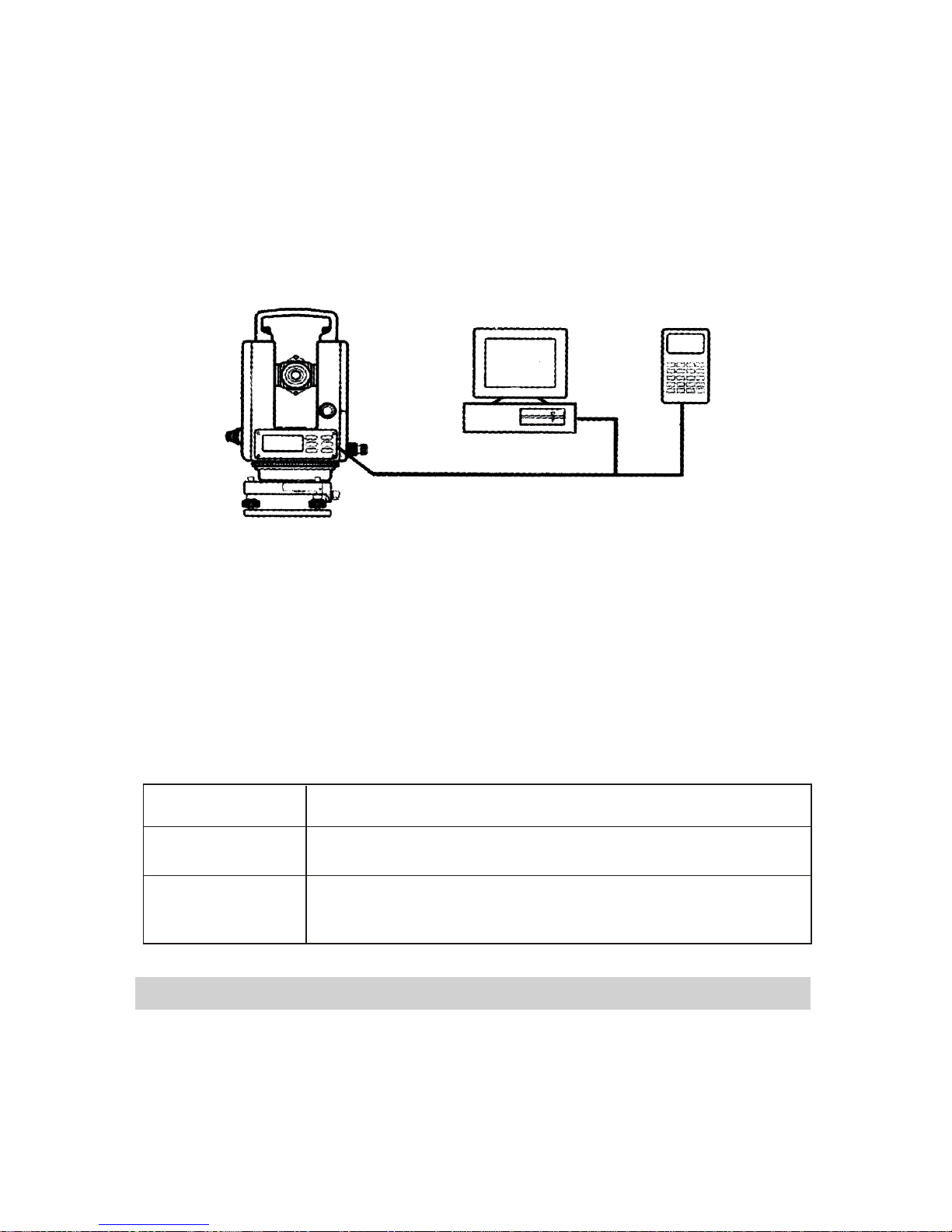
6. Recording and outputting data
6.1 RS-232 serial communication interface
6.2 Recording measurement data
7. Memory mode
8. Function setting
8.1 Function setting
8.2 Function setting method
8.3 Time setting
9. Vertical angle 0 error and collimation error and tilt
angle compensator 0 error
10. Other function
10.1 Measuring distance
10.2 Tilt correction function
10.3 Illuminate and the timing close
11. Check and adjustment
11.1 Check and adjust plate level
11.2 Check and adjust circular level
11.3 Check and adjust vertical cross-hair
11.4 Collimation of the instrument sight line
11.5 Check and adjust optical plummet
12. Tribrach
13. Error display
14. Specifications
15. Accessories
R
RL
2
OUT
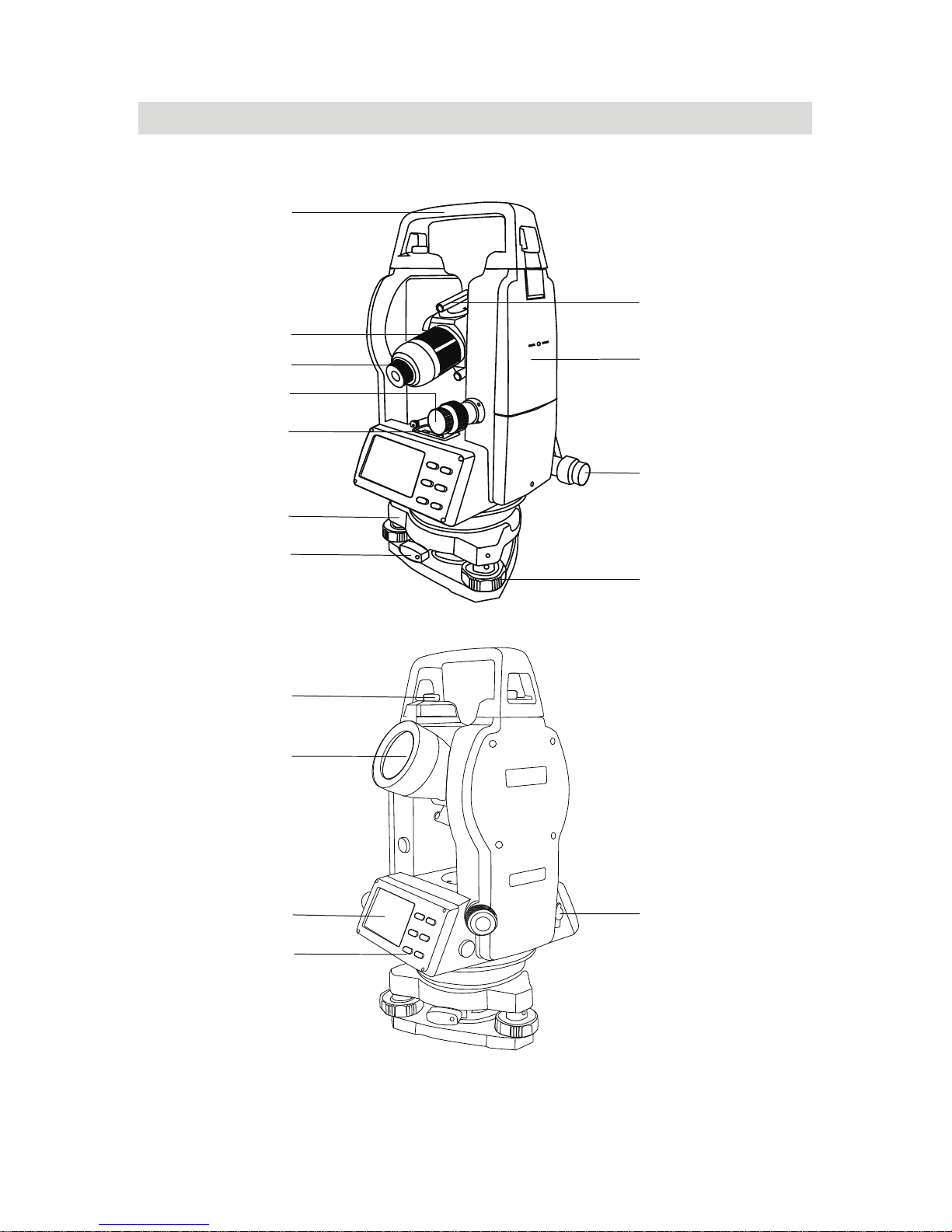
1. Nomenclature
1
13
10
4
8
11
16
12
15
14
3
6
2
7
5
9
3
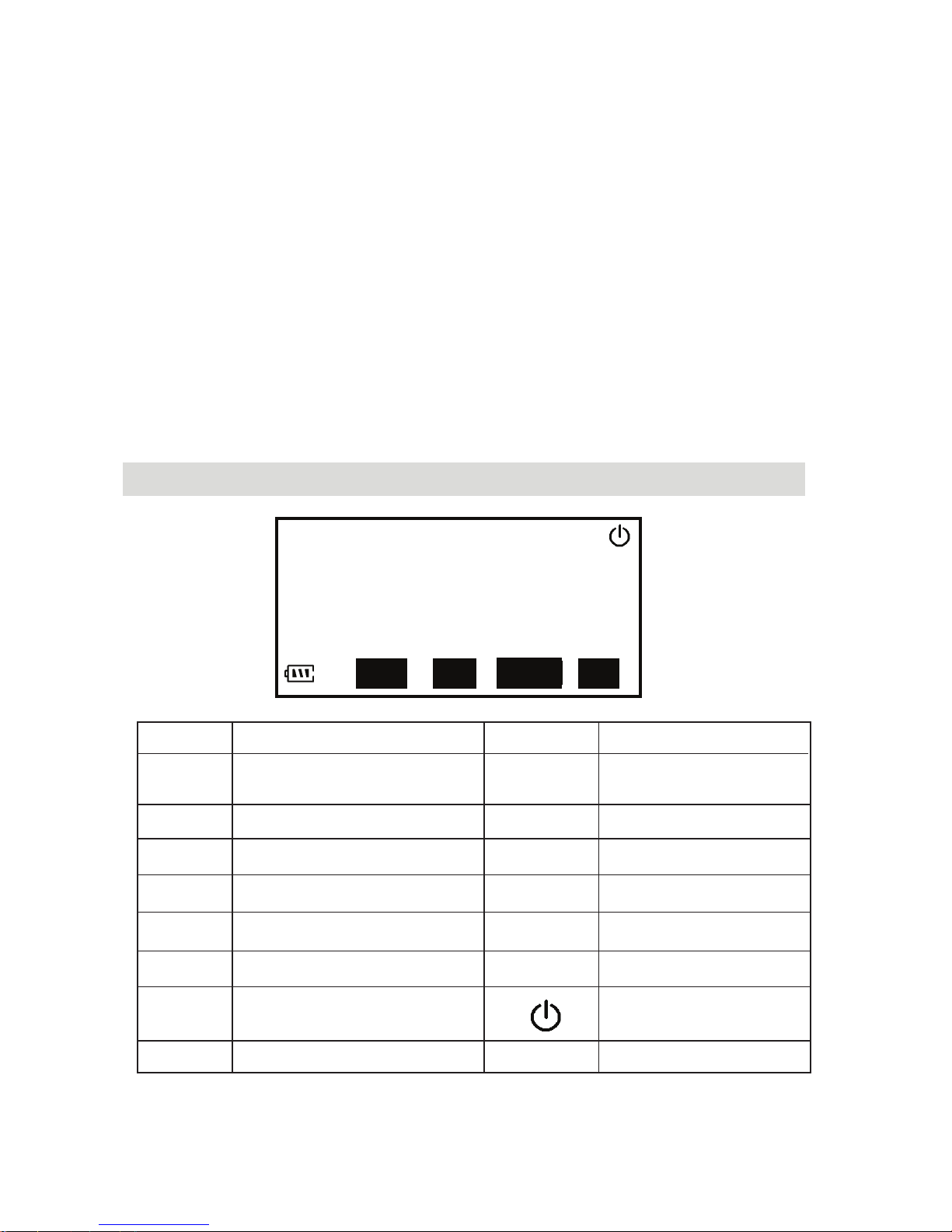
2. Display and display mark
SDHDVD
%
VA 9 0°00
′00
″m
HA
L
R
R
0°00′00″
gon
NCR
RE
P
H
OL
D
SF
T
11-03-20 15:48
1. carrying handle 2. handle screw
3. sighting collimator
4. vertical tangent screw and motion clamp
5. operating key
6. RS-232C communication interface
7. object lens 8. plate level
9. display window 10. eyepiece
11. base plate 12. foot screw
13. focusing knob 14. battery
15. horizontal tangent screw and motion clamp
16. base locking lever
Display Function Display Function
SD
HD
VD
VA
slope distance
horizontal distance
height difference
vertical angle
hold the
horizontal angle
HOLD
%
m
gon
percent grade
distance unit: m
angle unit
4
REP
SFT
HA
CRN
Tilt correction
horizontal angle right
the second function
repeat the horizontal
angle
11-03-20
date
15:48 time
auto power off

OSET
HOLD
SFT
R/L
REP
S/H/VDIST
REC
V / %
3. Operating keyboard and operating key
Keys Function 1 Function 2
OSET set horizontal angle 0 distance measurement
HOLD
R/L
V%
hold the horizontal
angle
repeat measurement
horizontal angle
turn on or off
illumination
select the second
function
switch horizontal
angle right or left
switch SD/HD/VD
display
percent grade of
vertical angle
record measurement
power switch
5
4. Preparative before measurement
4.1 Level the instrument
Level and center the instrument correctly to ensure the best
performance.
4.1.1. Place the tripod
First, put the tripod leg in the proper position and tighten the
locking screws.
4.1.2. Attaching the instrument to the tripod head
Place the instrument carefully on the tripod head, and move
the instrument slowly by loosening adjusting screw. Align the
plumb bob with the point on the ground when aligned, tighten
the adjusting screw.
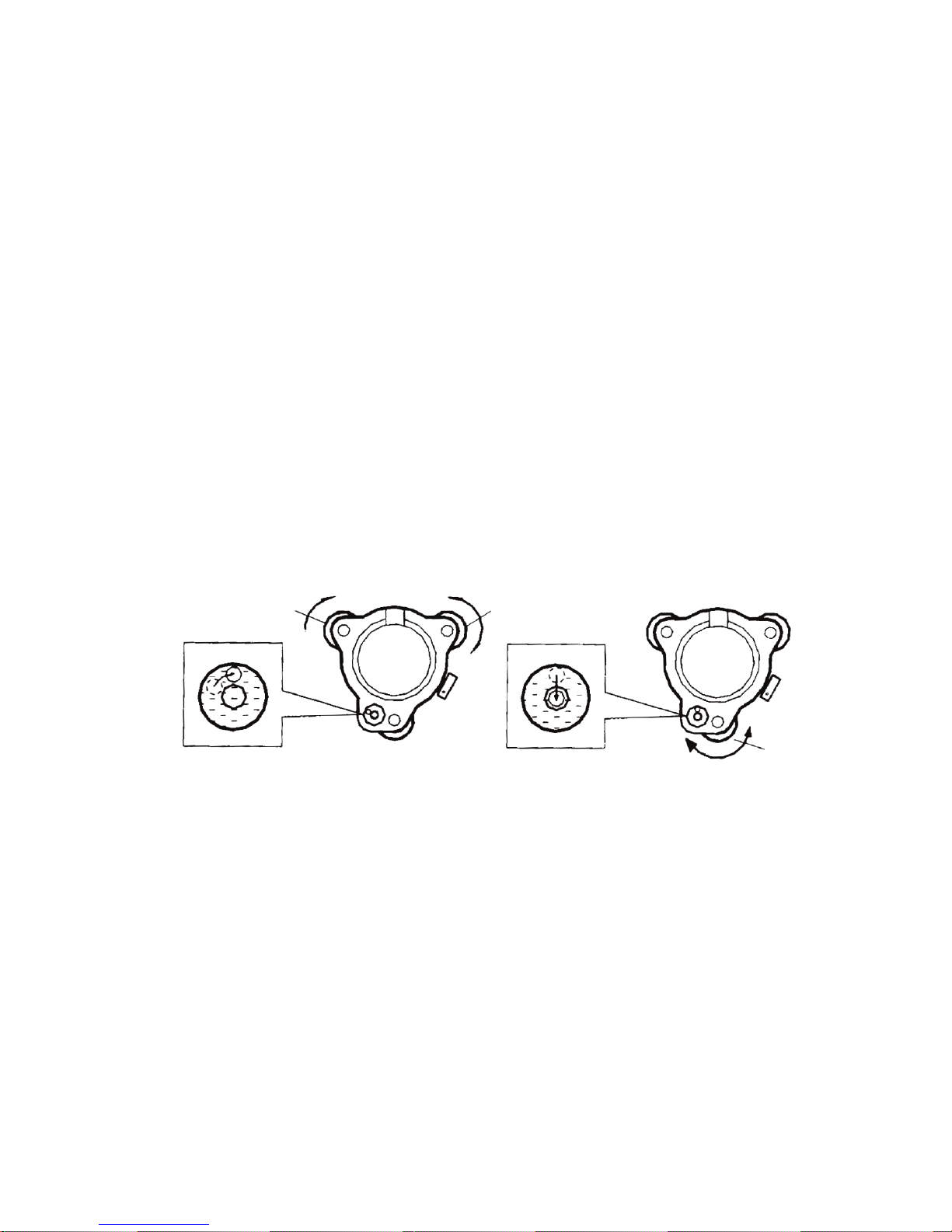
4.1.3. Initial rough leveling the instrument with circular level
a. Use leveling screws 1, 2 to move the bubble of the circular
level until the bubble of the circular level is located on a line
perpendicular to a line running through the centers of the
two leveling screw adjusted.
b. Revolve the leveling screw 3 to shift the bubble to the center
of the circular.
6
4.1.4 Further leveling the instrument with plate level
a. Loose horizontal motion clamp and revolve the instrument.
By adjusting leveling screw 1, 2, the plate level vial is parallel
to a line running through the centers of two leveling screws,
and place the bubble in the center of the level vial.
b. Next, revolve the instrument 90 (100g) around its vertical
axis and use the remaining screw 3 to center the bubble
once more.
o
bubble bubble

c. Repeat the above procedure for each 90 revolution of the
instrument and check whether the level bubble is correctly
centered for all points.
4.1.5. Centering the instrument with optical plummet
Adjust the eyepiece of the optical plummet telescope to the
user’s eyesight. Move the instrument by loosening with the
center mark of the optical plummet telescope. Carefully move
the instrument in order to make it steady.
4.1.6. Final leveling of the instrument
Repeat procedure of 4, and check whether the level bubble is
in the center of the level vial. Finally tighter adjusting screw.
4.2 Power switch on
1. Press
, all segments of display with light on. The display
shows that vertical angle should be sent to zero.
2. Rotate the telescope to set the instrument to a vertical angle
reading of 0.
3. Press over 2 seconds, it can be power off.
o
o
7
symbol reticle center
1 2
3
90

Note:
a. In order to make sure instrument work continuously, pay
attention to battery power display. if battery power is insufficient,
replace battery. please see 4.3 Battery power display.
b. For setting the vertical angle at 0, a datum 0 is provided on
the vertical angle scale circumference. If the telescope is
turned and the sensor passes the datum 0, angle measure
-ment begins.
8
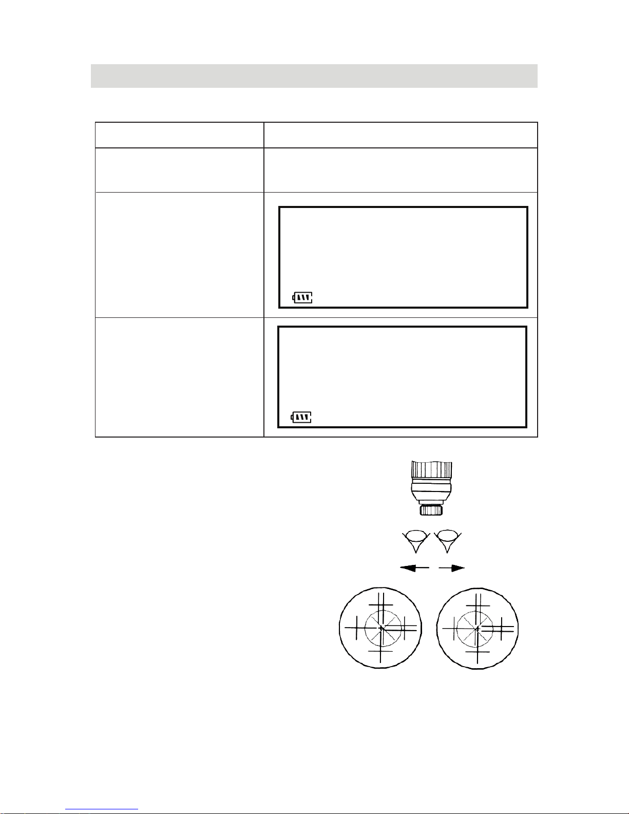
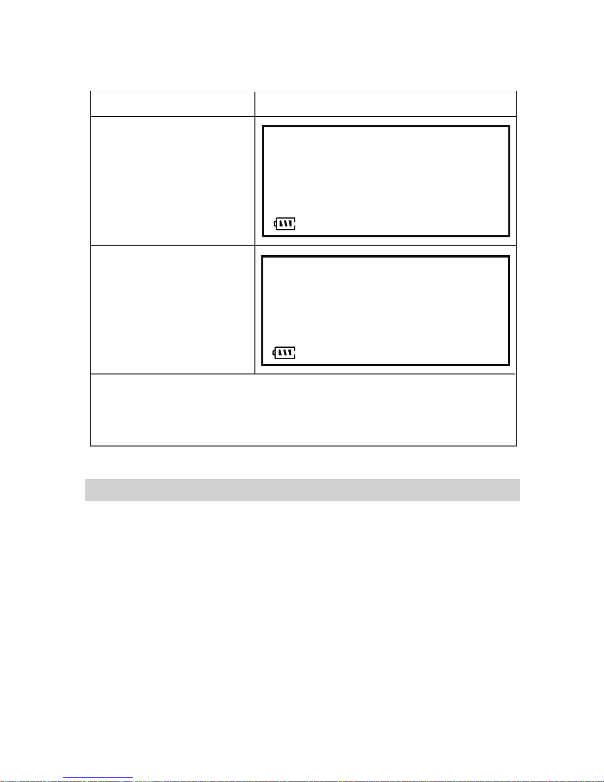
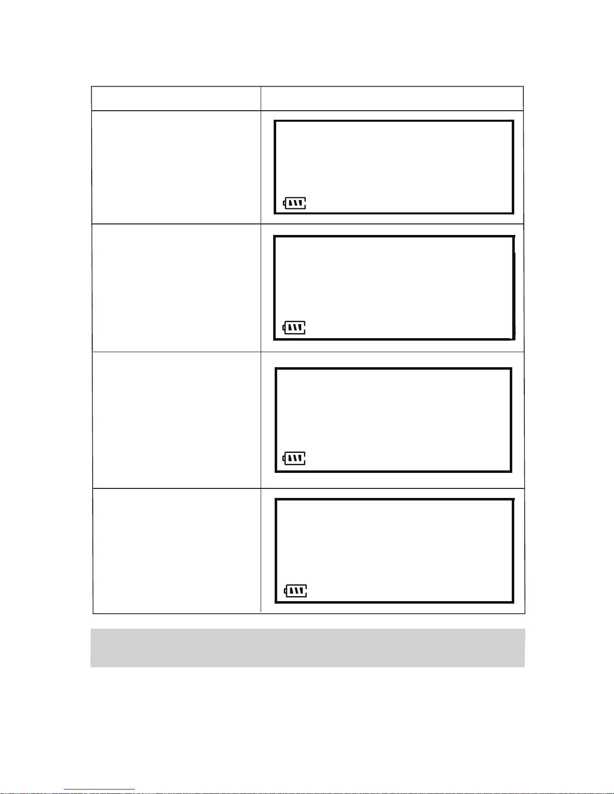
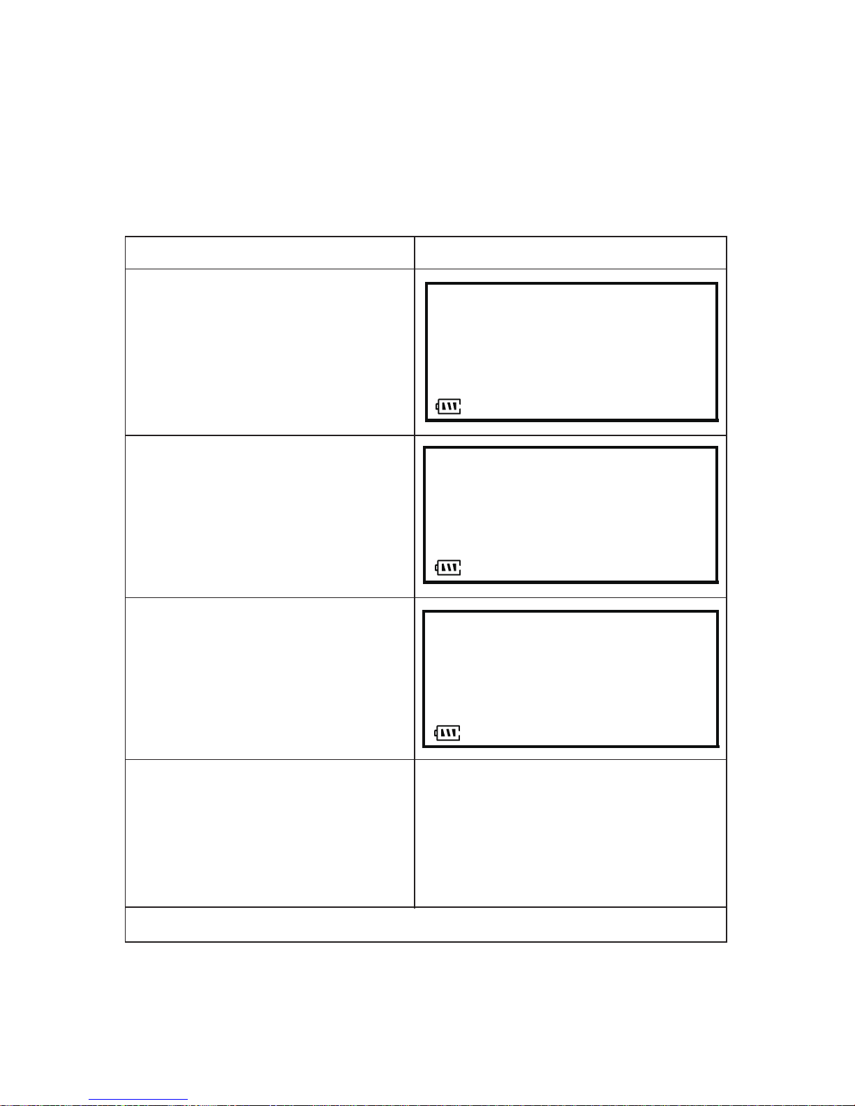
mark meanings
sufficient battery power(90% - 100%)
effective battery power(50% - 90%)
effective battery power(10% - 50%)
poor battery power(0-10%), need to replace battery.
measurement is impossible, the power will be
cut off in one minute.
4.3 Battery power display
4.4 Change the battery
4.4.1. Removing the battery case
a. Press the release button of the battery case and hold it on.
b. Pull the battery case toward your side.
c. Remove it out.
4.4.2. Installation battery case
a. Put the battery in the battery case.
b. Press the release button and hold the battery case toward
the groove in the instrument.
5. Angle measurement
5.1 Measuring a HARand vertical angle
1. Collimate the first
target.
2. Press【 】
0°00′
00
″
VA 90°00′00″
HA
R
0°00′00″
VA 90°00′00″
0°10′00″
5.1.1. How to collimate
0SET
twice, and set
horizontal angle
of target A
11-03-20 15:48
11-03-20 15:48
HA
R
a. Point the telescope towards
the light. Turn the diopter ring
and adjust the diopter so that
the cross-hair is clearly
observed.
3. Collimate the
second target B,
and the horizontal
and vertical angle
are displayed.
operating display
9
b. Observe the target with
sighting collimator, allow
a certain space between
the collimator and yourself
if for collimating.
c. Focus the target with focusing knob.

90
°
00
′
00
″
HA
HA
R
R
R
0
°
10
′
01
″
VA
VA
90
°
00
′
00
″
L
L
L
359
°
49
′
59
″
1. Collimate the target
A.
11-03-20 15:48
11-03-20 15:48
【
R /L
】,
R
L
2. Press
the mode horizontal
angle Right HA
switches to HA
mode.
R
3. Measure the target
in the same manner
as HA mode.
【R /L】
Everytime key is pressed, HA /HA
mode switches.
operating display
5.2 Switching horizontal angle HA /HA
5.3 Setting a horizontal angle
1. Turn horizontal
tangent screw and
set the horizontal
angle required
VA 90
°00′00″
R
30°00′00″
2. Press
【
】
VA
90°
00
′
00
″
HA
R
30
°
00
′
00
″
3. Collim ate the
target
4. Press【HOLD】
VA 90
°00′00″
HA
R
30°00′00″
11-03-20 15:48
11-03-20 15:48
11-03-20 15:48
H
OL
D
HA
HOLD
key twice and the
horizontal angle is
hold.
key again to stop
holding the
horizontal angle.
operating display
10

To find the horizontal angle with greater precision, perform
repetition measurement.
【
SF T
】,and
【
H O LD
】
A .
【OSET , and
】
°00
′
00
″
1. Press
then press
to begin repetition
angle measurement.
2. Collimate the target
0
N - 0 T2
HAR
0
°00′00″
RE
P
SF
T
11-03-20 15:48
N - 0 T1
HAR30°00′00″
RE
P
SF
T
11-03-20 15:48
5.4 Repetition angle measurement
3. Press
make the horizontal
angle of A is
11
operating display
4. Collimate the second
target B using the
horizontal tangent
screw and motion clamp
【
H O LD
】,
5. Press
and hold the
horizontal angle.
N
-
0 T2
HA
R
45
°
00
′
08
″
11-03-20 15:48
RE
P
SF
T

12
6. Recollimate the first target
A using the horizontal
tangent screw and
motion clamp.
N
-
1 T2
HA
R
0
°
00
′
00
″
11-03-20 15:48
RE
P
SF
T
【】,
and
°
00′
00″
7. Press
make the horizontal
angle of A is
OSET
0
N
-
1 T2
HA
R
45
°00 ′06 ″
【
H O LD
】
N
-
2 T1
HAR
45
°00′07″
~
【
S FT
】
8. Recollimate the second
target B using the
horizontal tangent
screw and motion
clamp.
9. Press
The average of
angle is shown
10. Repeat 2 9 to
measure the desired
number of repetitions
The maximum number of angle measurements that
can be made is 9.
Press to exit from this mode.
11-03-20 15:48
RE
P
SF
T
11-03-20 15:48
RE
P
SF
T
VA
-
3.108 %
HA
R
30°00′00″
VA 91°46′50″
HAR 30°00′00″
11-03-20 15:48
11-03-20 15:48
6. Recording and outputting data
The provide function of recording measurement data. The angle
data and the distance data can be stored in the instrument’s
memory (up to 500 groups) or output through communication
interface.
The recorded data includes time information. Before recording
data, the recording method should be selected. If recording
data through communication interface is selected, the communic
-ation settings should be made properly (please see “function
setting”).
13
【V %
】,
【V %】
【V %】,
±
1. Press
display of vertical
angle switches to
percent grade.
2. Press
The display turns
back to normal angle
measurement mode.
Every time pressing the display mode will be
when measured grade is exceeding 100%,
“EEEEE. EEE” is displayed.
5.5 Measuring a percent of grade(slope measurement)
switched.
the
again.
operating display
【
SFT
【V%】,the measurement data can be outputted to the computer
6.2 Recording measurement data
In the different measuring mode, press , and then press
】
or PDA (when selecting method of recording data through com-
munication interface), or stored in the memory of the instrument
(when selecting method of recording data in the memory).
mode output (record)
angle mode VA, HAR (vertical angle, horizontal angle)
distance
mode VA, HAR, SD (vertical angle, horizontal
angle, slope distance)
6.1 RS-232 serial communication interface
The series instrument has RS-232 interface joined with the
computer or PDA through the cable. The measurement data
can be transferred to the computer or the data collection equip
-ment. Remember the interface is under the vertical knob.
14
In the memory mode, the data recorded in the memory can be
cleared or be outputted to the communication interface.
7. Memory mode

【
V %
】
,
N 3
【
REC
】
,
11-03-20 15:48
1. Press
come in the memory
mode.
The first line display the
effective data items in
the memory.
N 3
11-03-20 15:48
2. Press
line will glint, and the instru
-ment output the data to
the interface, until it finish
-ed, it will not glint. ----------------
----------------
power on,
the second
15
operating display
【
HOLD
】
,
【
HOLD
】
3. Press
line will glint, press
all the data in the memory
will be cleared, and after
doing this, the instrument
exit from the memory mode
and enter the angle measure
-ment mode.
VA
91
°
46
′
50
″
HAR
30
°
00
′
00
″
11-03-20 15:48
【SFT】,
In the memory mode, press
mode, return to the angle measurement mode.
the first
again in 5 seconds, then
exit from the
8. Function setting
8.1 Function setting
This series instrument provide many functions can be configur
-ed by user.
1. Tilt angle compensation: OFF, ON.
2. Vertical angle level 0: 90 (OFF),
OO
0 (ON).
3. Automatic power off: OFF, ON (if no operation in 20 minutes,
turn power supply off automatically).

4. Minium angle display: 1’ , 5’’, 10’’.
5. Setting communication baud rate: 1200, 2400, 4800, 9600.
6. Selecting data recording method: interface(OFF), memory(ON).
7. Collimation error correction: OFF, ON.
8. Selecting angle unit: dms (OFF), gon (ON).
8.2 Function setting method
In the setting mode, the keys are assigned function as following:
16
【
OSET】
:Select the item circle.
【HOLD
】
:
【L/R】
:
Select the time item(month, date, year, hour, minute).
Select the upwards item or the time item add 1.
【V% 】:
Select the downwards item or the time item minus
1.
【SFT】
:
Confirm the setting, exit the setting mode, return to
angle mode.
【S F T】,and then
【L/R】,come in
1. OFF
【
S E T
】
2. OFF
【L/R】【V %】,
2. ON
【S FT】to finish
VA
91°46′50″
HA
R
30°00′00″
1. Press
press
the setting mode.
2. Press
3. Press
4. Setting all the item as
you need.
5. Press
setting return to the angle
measurement mode.
11-03-20 15:48
11-03-20 15:48
11-03-20 15:48
11-03-20 15:48
operating display
Oto select
the item (1 7).
_
or
change the setting of
the selected item.
11-03-20 15:48
【
SFT】
then press
【L/R】
1. OFF
【
HOLD
】to
· · · · · ·
【L/R】
【V %】,
· · · · · ·
· · · · · ·
1. Press
come in the setting
mode.
11-03-20 15:48
11-03-20 15:48
11-03-20 15:48
2. Press
select the item
(month,data, year,
hour,minute,second),
the selected item
will glint.
3. Press
minus it.
4. Finish setting of
all item.
8.3 Time setting
operating display
, and
or
add or
17
9. Vertical angle 0 error and collimation error and
tilt angle compensator 0 error correction
With this option, making both face angular observations, you
can measure and adjust tilt compensator 0 position error. and
you can measure collimation error in your instrument so that
the instrument can correct subsequent single face observations.
The 0 index of the vertical circle of your instrument can be also
reset, and the index error that will affect the accuracy of vertical
angle measurement can be corrected.
18
operating display
【R/L】
SET F1
HA
R
0°00′08″
1. Press and
power, it will display
“SETUP” and “SET 0”,
rotate the telescope,
the first line will display
“SET F1” and will glint.
11-03-20 15:48
if you want to exit at any time, you can press
.
【 】
【
【
】
】
2. Level the instrument and
make the plate at left,
collimate the target at
infinitude press ,
the first line will glint and
display “SET F2”.
OSET
OSET
【】
OSET
3. Make the plate at right
and then collimate the
same target, press
the first line will glint
and display “SET”.
4. Press the instrument
perform the new data of the
vertical error, the telescope
axis error and the
compensator 0 error, and
return to the angle mode.
11-03-20 15:48
SET F2
HA
R0°00′08″
SET
HAR179°59′58″
11-03-20 15:48
SFT
Note: After adjustment above finished, you should check again.

Measuring distance with the cross-hair in telescope reticle is
another application of the theodolite series products. This is
a simple method, but scale station pole is needed, for example,
horizontal measuring staff and apparent distance staff. By view
-ing through the telescope, the length between upper and lower
stadia hairs multiplied by 100 is the distance from the instrument
to the station pole(the length refers to the reading from station
pole between two stadia hairs).
10. Other function
10.1 Measuring distance
1. First fix the station pole at the measuring point.
2. Level instrument.By viewing through the telescope, make
sure the reading between two stadia lines.
3. The distance from instrument plumb bob center to station
staff “L” is 100 times of “I”, L=100 x I.
19
10.2 Tilt correction function
This instrument provide vertical axis incline compensator. It can
compensate the cline angle automatically. When the incline sensor
is switched on, the instrument can detect the vertical axis incline
angle. When instrument inclines over the compensator range,
it displays “TILT”. You should level the instrument manually.
L= 100 x l
l
stadia hairs
Table of contents
Other SitePro Laser Level manuals


