Sitron CF12 DC User manual

CF12 AC / CF12 DC
Thermal dispersion
Flow switch for Low Flow
USER’S GUIDE
Installation, Operation

03
Contents
Introduction . . . . . . . . . . . . . . . . . . . . . . . . . . . . . . . . . . . . . . . . . . . . . . . . . 4
Models & Dimensions . . . . . . . . . . . . . . . . . . . . . . . . . . . . . . . . . . . . . . . . . 5
Wiring Diagram . . . . . . . . . . . . . . . . . . . . . . . . . . . . . . . . . . . . . . . . . . . . . . 6
CF12 Relay Status Guide . . . . . . . . . . . . . . . . . . . . . . . . . . . . . . . . . . . . . . 8
Installation . . . . . . . . . . . . . . . . . . . . . . . . . . . . . . . . . . . . . . . . . . . . . . . . . . 9
Calibration . . . . . . . . . . . . . . . . . . . . . . . . . . . . . . . . . . . . . . . . . . . . . . . . . 10
Technical Specifications . . . . . . . . . . . . . . . . . . . . . . . . . . . . . . . . . . . . . . 11
Ordering Information . . . . . . . . . . . . . . . . . . . . . . . . . . . . . . . . . . . . . . . . . 12
Trouble Shooting . . . . . . . . . . . . . . . . . . . . . . . . . . . . . . . . . . . . . . . . . . . . 13
Terms & Conditions . . . . . . . . . . . . . . . . . . . . . . . . . . . . . . . . . . . . . . . . . 14

04
Introduction
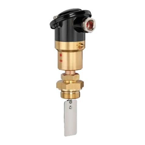
The CF12 series of thermal flow switches is designed to monitor flow status of
liquids and gases and can also be used to detect level.
A chain of 8 LED's gives the user a visual indication of the flow status of the
switch.
There are two red LEDs that indicate whether or not the unit has detected flow,
a yellow LED to indicate the set point (for increasing or decreasing flows) and 5
green LEDs that indicate the amount of flow beyond the set point of the unit.
The CF12 also includes a di-chromatic (red/green) LED which shows the
switch point status of the unit.
The sensing element and connection of the CF12 are made with 316L S.S. and
can be coated when necessary .
The enclosure is offered in either glass filled nylon or aluminum. All models
can be ordered with a great variety of threaded, flange, or sanitary process
connections.
With the addition of a built in “T-Reducer” connection, the CF12 is now able to
detect flow rates between 3ml and 300ml per minute.
Characteristics
Simple to install.
Excellent low flow sensitivity.
No moving parts-maintenance free reliabity.
Maximum working pressure of 1450 PSI (100 bar).
Fast response time for flow or level (Adjustable from 1-10 seconds).
Thermal dispersion
Flow switch for Low Flow

05
Models & Dimensions
Mounting Options
126mm
130mm
130mm
89mm
76mm
89mm
Nylon-N1 Aluminum-G1 Aluminum-G2
Body Dimension (standard)
6
Hex. 1 1/2"
BSP/ NPT female
49
110
More connections upon request

06
Electrical Connections
Standard Connection w/
2 meters of Cable
+
_
Bargraph (B1)
Bargraph (B1)
Adjust (P1)
Adjust (P1)
Central LED Status (L1)
(Red/Green)
Central LED Status (L1)
(Red/Green)
Adjust
CF 12 DC
Adjust
Red
White (NC)
Green and
Yellow
or solid Yellow
Blue (common)
Green (NO)
Black
Power
Supply
Contacts
Ground
CF 12 AC
2000mm
1
2
Connector
12mm
NO or NC
contact
2000mm
1
2
Connector
12mm
+
++
_
__
NO or NC
contact
Nylon Enclosure (N1)
M12 Connector Optional
M12 Connector Optional
1 - Power Supply (+)
2 - Power Supply (-)
3 - Ground
4 - NO Contact
5 - Common
6 - NC Contact
1 - Power Supply
2 - Power Supply
3 - NO Contact
4 - NC Contact
5 - Common
1 - Power Supply (+)
2 - Power Supply (-)
3 - NO Contact
4 - NC Contact
5 - Common
1
1
5
5
2
2
3
3
4
4

07
Electrical Connections
Aluminium Enclosure (G1/G2)
2SPDT
Bargraph (B1)
Flow 100 %0
+
-
1 2 345 6 7 9
8
CF12
+
_
1 2 3 4 5 6
Adjust
1SPDT
Bargraph (B1)
G2
G1
1 - Power Supply (+)
2 - Power Supply (-)
3 - Ground
4 - NO Contact
5 - Common
6 - NC Contact
(P1) - Set Point Potentiometer Adjust
(B1) - 8 LED´s Bargraph: Red LED
Yellow LED
Green LED
(L1) - Central LED - Green: With flow
Red: No flow
1 - Power Supply (+)
2 - Power Supply (-)
3 - Ground
4 - NO Contact
5 - Common
6 - NC Contact
7 - NO Contact
8 - Common
9 - NC Contact
Central LED Status (L1)
Red/Green
Adjust (P1)
Central LED Status (L1)
Red/Green
Adjust (P1)
( )
( )
( )
( )

08
Sentido Fluxo
Sentido Fluxo
CF12 Relay Status Guide
Application Condition
No Flow
Flow
LED Status
RED
GREEN
Set Point
OFF
ON
CF12 SPDT
Status
NO (4) NC (6)
C (5)
C (5)
NO (4) NC (6)

09
Installation
Fig. 3
Pump
Fig. 2
Fig. 1
5xØ
Flow direction
1/2 meter
Sentido Fluxo
Fig. 4
Checks:
The flow switch must be installed so that the flow
direction follow the flow direction description tag.
1) Its recommended that the flow switch is
installed with a distance of ½ a meter of the pipe
bent where the flow enters and 5x times the
diameter of the pipe where the flow exits, enabling
it to have an accurate reading (Fig. 1).
Verify that the installation point isn’t near any
connections, valves, elbows or anything similar,
this can cause errors in the reading of the probe
due to turbulence in the pipe.
2) It is important that the flow switch is not installed
at the highest point in the pipe run or in a location
where there is the risk of air accumulating in the
pipe. Keep in mind that the ideal mounting
location is where the pipe is always full. This will
ensure that the switch is always immersed in the
flow. (Fig. 2 correct)
3) In pipes that have pressure pumps or retention
valves, we recommend that the probe be installed
before the pump due to the fact that it will have
less turbulence. (Fig. 3)
4) Confirm that the wire connections are correct
and that the available power supply is compatible
with the CF12 unit.
5) Verify that the operating pressure and
temperature of the process corresponds to the
operating parameters of the CF12 unit.
Do not expose the CF12 to excessive heat and
rain, avoid damaging the performance by making
adequate protection (Fig.4)
Flow direction
Flow direction

10
Calibration
Adjust
Adjust
0% 100%
BARGRAPH Lights ON
Set Point
0% 100%
BARGRAPH Lights Off
Set Point
Led Status
Red
Led Status
Blinking
To Start:
1 - Remove the enclosure lid (Note: the screws are self-retaining)
2 - Start the power supply and wait 5 minutes until the CF12 is active and has reached a
stable point within the medium.
3 - Let the regular or desired flow reach its point of normal operation.
Calibration for Flow / No Flow:
1 - Set the flow rate at the normal range of operation.
2 - Turn the potentiometer counter-clockwise until the central LED turns red.
3 - With the central LED red, turn the potentiometer clockwise until the central LED
changes to a blinking green state.
4 - Continue to turn the potentiometer clockwise until the first 3 green LEDs in the bar
graph turn on.
Set Point Adjustment:
The flow switch can be adjusted to indicate either increasing flow, or decreasing flow at
a specific set point within 3ml to 300ml/m.
It is important to determine the specific set point at which the flow switch should activate
or de-activate.

11
Technical Specifications
CF12DC / AC
Flow 100 %0
+
-
1 2 345 6 7 9
8
1 2 3 4 5 6
Repeatability
Application
Operating Voltage
Current Consumption
Electrical Connection
Operating Temperature
Gradient Temperature
Set Point Range
Output
Flow Rate Indication
Max Pressure
Accuracy
Response Time
Enclosure Material
Wetted Material
Class Protection
Process Connection
+/- 10%
1 to 10s
15ºC/min
Liquid: 3ml to 300ml/min
+/- 1% setpoint
Cable gland w/ 2000mm cable, M12 connector or ½” NPT
Red led - flow is below setpoint
Yellow led - flow is at setpoint
Green led - flow is above setpoint
1450 PSI (100 Bar)
IP 65 - Nylon (N1)
IP 66 - Aluminum (G1/G2)
Glass filled nylon / Aluminum painted
316L Stainless Steel
1/4" to 1/2” BSP or NPT (others upon request)
14 to 176º F (-10 to 80ºC)
Low Flow monitor for liquids
DC: 24 VDC (+/-10%)
AC: 85-264Vac (50/60hz) & 125Vdc
+/- 100mA
Relay (SPDT) 5A - 250Vac (N1/G1)
2 SPDT 5A-250VAC - G2
N1 Enclosure
G2 Enclosure
G1 Enclosure

12
Order Code
CF12AC
CF12DC
MODEL
F12
SIZE CONNECTION
T1
T1F
T2
T2F
1/4" (Female)
3/8" (Male)
3/8" (Female)
B
N
BSP
NPT
OTHER - SPECIFY
LT Standard
HOUSING
SC
N1
NB
NE
NT
G1
G2
NO ENCLOSURE
SMALL NYLON
N1 SHIELDED
N1 Encapsulated
NB + NE
SMALL ALUMINUM (1SPDT) 5A-250Vac
LARGE ALUMINUM (2SPDT) 5A-250Vac
0
1
2
3
4
5
6
7
8
9
C
J
M
P
ELECTRICAL CONNECTION
NONE
1/2" BSP (N1/G1/G2)
CABLE GLAND W/ 1/2" BSP (N1)
CABLE GLAND W/ 1/2" BSP - 2m CABLE (N1)
3/4" BSP (G1)
CABLE GLAND W/ 3/4" BSP (G1)
1/2" NPT (N1/G1/G2)
CABLE GLAND W/ 1/2" NPT
CABLE GLAND W/ 1/2" NPT- 2m CABLE (N1/G1/G2)
3/4" NPT (G1)
CABLE GLAND W/ 3/4" NPT (G1)
M15.8 Connector (9Pins) (G2/G1)
M12 Connector (4 or 5 pins for CF12AC) (N1)
M20 threaded (N1/G1/G2)
PROCESS CONNECTION TYPE
INSERTION LENGTH
SNONE
COATING
CF12DC T1 NSL50 N1 7
X
RANGE
3ml/min to 300ml/min
F1
F1
T3
T3F
1/4" (Male)
1/2" (Male)
1/2" (Female)
LT

13
Fault
Relay does not
change state.
LED off, no power
LED doesn’t change color
Check the installation
(insertion length)
Verify the calibration
Check power supply
Cause Solution
Radio frequency
interference
Sensor is potentialy
defective
Flow switch
turns on or
off suddenly
Relay remains
closed
Use armored cable
and shielded housing
Contact Sitron or your
local representative for
further instruction
Trouble Shooting

14
Terms & Conditions
Sitron's TERMS & CONDITIONS
Design: Sitron reserves the right to make any alterations or changes necessary to
improve the Products, correct defects or to make the Products safer, without prior notice
or consent by Buyer.
Pricing: All stipulated amounts shall be in US dollars and all prices quoted are valid for
thirty (30) days from date of offer, unless otherwise stated.
Safety and Instructions: The Buyer ensures that it and all its representatives and agents
will observe all safety and technical instructions in Sitron's operating manuals, catalogs
or other directions or instructions (either written or verbal).
Delivery and Freight: All goods are sold FOB point of shipment, Brasil. Transportation
to the destination is the Buyer's responsibility and Buyer alone shall bear the cost of
freight, optional or other shipping requirements, and or insurance. Sitron shall not be
liable for loss or damage to the Products after said Products are delivered to or received
by the shipper/carrier, and all risk of damage or loss shall immediately pass to Buyer.
Receiving, unloading and storing of Products will be the responsibility of the Buyer.
Buyer also accepts that courier may choose to return Products to Sitron if any local
taxes or duties are not paid by Buyer at point of delivery. Buyer must make any and all
claims for corrections or deductions within ten days of the delivery of the Products.
Shipment Delays: Sitron has no control over the length of time shipments may be held
at customs, etc. For this reason, Sitron commits only to a "shipment date", not a
"delivery date". Buyer shall not hold Sitron liable for claims resulting from delay in
shipment except in cases where these terms are accepted in writing by Sitron.
Acceptance of delivery of Products by Buyer shall constitute a waiver of all claims for
delay.
Partial Deliveries: While Sitron strives to deliver all orders on time and complete,
Sitron reserves the right to make partial deliveries when necessary.
Changes: Any changes initiated by the Buyer which affects the products specifications;
quantities ordered; delivery schedule; method of shipment or packing; or delivery
location, must be made in writing and signed by both parties.
In this case, Sitron reserves the right to adjust the pricing and or delivery of the order,
which will be agreed to by both parties before further work is performed on the order.
Any such requests will be priced according to the scope of changes and the status of the
current order. Customer must sign and return or acknowledge approval of drawings
along with any Purchase Order. If approval drawings are not returned with order, the
delivery date may be held or pushed back until Customer has acknowledged approval.
Cancellation: Any cancellation of the Contract by the Buyer shall be effective only if
made in writing and accepted, in writing by the Sitron. In such a case, Sitron is entitled
to reasonable cancellation charges including but not limited to labor, material and other
related expenses.

15
Termination Fee Schedule:
Order entered but not released for manufacturing 10%
Order in any stage of production 75%
Order complete and ready for shipment 100%
Warranty: Sitron warrants its product against manufacturing defects in material and
workmanship, when installed in applications approved by Sitron, for a period of one year
from the date of original shipment, unless otherwise stated in writing by Sitron.
Sitron is not responsible for damage to Sitron's Products or other equipment or products
because of improper installation or misapplication of the Products by Buyer. Installation
or startup of Sitron's equipment must be performed under the guidelines set forth in
Sitron's instruction manuals, wiring diagrams, etc., or performed under the direct
supervision of Sitron's field technicians or Sitron's authorized Sales Representatives, in
order to be covered by Sitron's warranty.
Sitron shall be under no liability in respect to any defect from fair wear and tear, willful
damage, negligence, abnormal working conditions, failure to follow Sitron's instructions
(whether written or verbal), misuse, modification or alteration or attempted repair of the
Goods without Sitron's approval.
Sitron shall not be liable under the above warranty (or any other warranty, condition or
guarantee) if the total price for the Products or the payment of Services rendered has not
been paid by the due date for payment.
The Buyer must make all tools, resources or personnel available to help Sitron to
diagnose the defect without any back charge. In absence of Buyer's cooperation in this
regard, there shall be no liability under the above Warranty.
Sitron's liability under this warranty shall be limited to repair or replacement at Sitron's
option of such defective Products, FOB factory, upon proof of defect satisfactory to
Sitron. Warranty does not include transport.
Return Goods: No goods may be returned without Sitron's permission and an RMA
number. Sitron assumes no responsibility for return shipments made without
permission. In issuing credit for such shipments, Sitron reserves the right to charge a
restocking fee dependent on Sitron's ability to recondition and resell the returned
equipment.
Insurance: The responsibility for insuring the Goods after the risk in them has passed to
the Buyer shall be that of the Buyer.
Confidential Information: All drawings, specifications, and technical information
provided by either Buyer or Sitron shall be treated as confidential and shall not be
disclosed to anyone other than those who require it as part of the fulfillment of the order.
Buyer agrees that the designs and/or any other related material provided are and
remain Sitron's exclusive property and that the Buyer acquires no right, title or interest to
this intellectual property, whether in whole or in part.
Errors: Sitron reserves the right to correct all typographical or clerical errors or
omissions, in its prices or specifications.
Terms & Conditions

Sitron - Brasil
R. Baronesa de Itu, 83
São Paulo - SP - 01231-001
T.: (5511) 3825-2111
F.: (5511) 3825-2171
www.sitron.com
BRASIL: [email protected]
Sitron - USA
1800 Prime Place
Hauppauge, NY 11788
PH: 516-935-8001
FX: 800-516-1656
08/18_rev 0
This manual suits for next models
1
Table of contents
Popular Switch manuals by other brands
3Com
3Com Switch 5500G-EI PWR 48-Port Quick reference guide

Compaq
Compaq Netelligent 1005 user guide

Moxa Technologies
Moxa Technologies EtherDevice EDS-205 installation guide

Alcatel-Lucent
Alcatel-Lucent OmniSwitch 6450-P10S Hardware user's guide
FM Systems
FM Systems VLS771-2 installation manual
Exsys
Exsys EX-1163HMS-WT manual
