Siyata VK7 User manual

Quick Installation Guide
ENGLISH | FRANÇAIS | ESPAÑOL
1-888-316-3747 www.siyata7.com

2
EN Installation Guide 5
FR Guide d'installation rapide 17
ES Guía de Instalación Rápida 30
Device Layout / Disposition de l’appareil /
Disposición del dispositivo

3
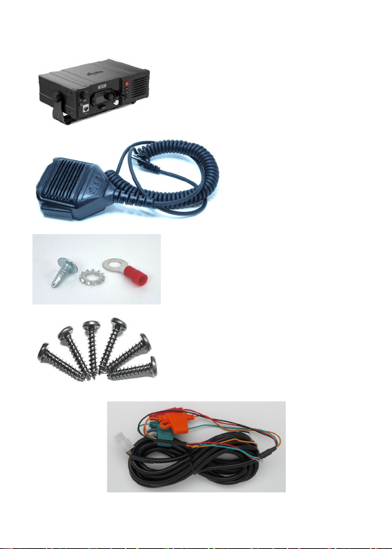
VK7 Parts / Pièces du VK7 / Partes del VK7
VK7 Device /
Appareil VK7 /
Dispositivo VK7
Wired RSM /
RSM filaire /
RSM cableado
Installation Kit /
Kit d’installation /
Kit de instalación
Power cord and fuses / Câble électrique et fusibles /
Cable de alimentación y fusibles

4
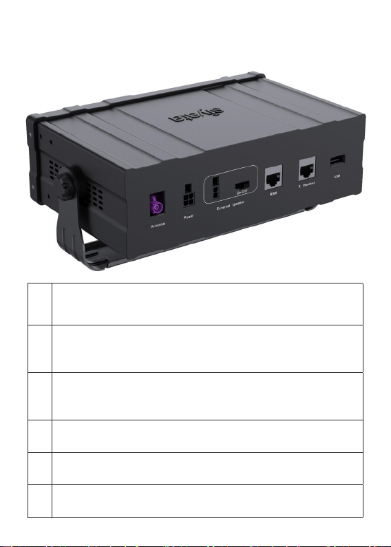
VK7 Rear View / Vue arrière du VK7 /
Vista posterior del VK7
1
External RF Rod Antenna Connection
Connexion d'antenne tige RF externe
Conexión a antena de varilla externa para RF
2
Power Cable Connection
Connexion de câble d’alimentation
Conexión del cable de alimentación
3
20 External Speaker Connection
Connexion de haut-parleur externe
Conexión a altavoz externo de 20 W
4Wired RSM Connection
Connexion du RSM filaire / Conexión RSM cableada
5Private Handset Connection / Connexion du combiné privé
Conexión de microteléfono con privacidad
6USB OTG Connection / Connexion USB OTG
Conexión USB OTG

5
English
ENGLISH
Table of contents
Preplanned Accessory Positioning ....................................... 6
Installing the Bracket and Device ......................................... 8
Installing the Speaker ........................................................... 9
Installing the Electrical Connections .................................. 10
Installing the RF Rod Antenna ............................................ 12
Troubleshooting ................................................................. 13
Optional Accessories ......................................................... 16

6
English
Preplanned Accessory Positioning
Positioning of all accessories must be planned in advance before
installation begins.
Ensure that no wire braids go through locations where Device
accessories are to be installed.
Ensure that any parts of the Device will not interfere with the
vehicle or its accessories’ operation
Plan Device and mounting bracket Positions
Note!
The best way to determine the Device’s position to
the customer’s full satisfaction is to locate it when
the customer is beside you and obtain his/her
approval.
Please ensure the Device’s location does not interfere
with the vehicle or its accessories operation: it should not
interfere with opening the glove compartment or ashtray,
should not prevent access to the lighter, moving the gear
stick, operating the hand brake etc.
If the Device is installed near the car windshield/dash board,
ensure that it does not interfere with the visual field.
Warning!
Do not install the Device in front of the vehicle’s air
bag. This restriction must be adhered to, as in the
case of an emergency the air bag blows up and can
fail to work properly.
Ensure the surface on which this Device is installed is
sufficiently strong to carry the weight and pressure which
would be exerted on it.

7
English
When selecting the Device’s location, please ensure the
control cable connected to it does not interfere with the
vehicle or its accessories’ operation.
Ensure it is safe and convenient to operate the Device from
the driver’s seat.
Ensure the Device would be protected from direct sunlight
and humidity (air conditioner openings).
Ensure the Device would be protected from mechanical
damage by the car’s accessories.
Plan the Wired RSM Position
For performance and user convienence, Install the device’s
Wired RSM using the bracket provided in kit by mounting it
on one of the VK7 side panels or on the Vehicle dash board in
a convenient location.
It is recommended to install the Wired RSM away from the
vehicle’s window and from external sources of noise.
Plan the External Speaker’s Position
(Optional accessory)
Note!
Do not hide the speaker inside the dash board.
If you cover it, sound quality will be lowered.
Locate the speaker at the right side of the main console, at
the front of the console, in a location where it would not
bother the driver or passengers but would sound best.

8
English
Installing the Bracket and Device
1. Disassemble the Bracket joint from its two base sided knob
units.
2. Install the Bracket Kit base unit using the 6 philips screws
provided with this kit.
Note!
Only use the original screws provided with this kit.
3. Put the Device to the Bracket Kit, adjust the angles. Use the
sided knob units in order adjust the Device
Device and Bracket Kit

9
English
Installing the Speaker (Optional accessory)
Where to Locate the Speaker (Reminder)
Note!
Do not hide the speaker inside the dash board.
If you cover it, sound quality will be lowered.
Locate the speaker at the
right side of the main console,
at the front of the console,
in a location where it would
not bother the driver or
passengers but would sound
best.
Installing the Speaker
1. Install the speaker at the right side
of the main console, at the front of
the console.
2. Disassemble the screws connecting
the speaker to the hanger.
3. Install the hanger using the 2 tin
screws.
4. Direct the speaker cable behind the mat located at the
bottom of the car.
5. Ensure the cable does not interfere with the vehicle or its
accessories’ operation.
6. Ensure the speaker cable is not exposed to damage by the
passengers.

10
English
Installing the Electrical Connections
The electrical cable is provided separately from the control
cable. Before installation begins, connect the four leads (which
include the 3A fuses) using a red or blue crimp sleeve as
appropriate.
Warning!
Please note sharp edges or moving parts which may
damage the wires.
The value for the fuses provided with the kits must
not be changed.
The kit is appropriate only for a 12V/24V vehicle.
In case of converting any other kit model into this kit,
please change the power cable.
The electrical cables should be directed as follows:
So as not to disturb the driver or passengers.
So as not to pass near the car’s sharp or moving parts.
Note!
The external voltage connection is located under the
dash board or close to the fuse box (depending on
the car model).
In new vehicles a cellular Device connection can be
found near the fuse box. See the car’s user’s manual
under Info.
Only use the kit’s original fuses (3A).

11
English
Installing the Voltage Cable
The following chart covers the manner by which the voltage
cable should be connected to the car’s electrical system.
Green: Ignition
Red: VCC
Black: GND
Orange: Mute
(usually unused)
Wire
Color Function Must be
connected to… Ensure…
Red To provide the
device with fixed
voltage
12V/24V fixed
voltage.
Connect with red
fuse case which
provided to a fixed
voltage source (+)
Ensure a 3A fuse
is used
Black To provide a fixed
minus (–)
Car body (minus) Ensure the
connection point
is on the car body
only.
Use a cable shoe,
tin screw and
springy disc
Green To turn on the
cellular Device
after switching
the ignition on
and turn it off
after car ignition
is switched off
IGN voltage.
Connect with
green fuse case
which provided
Determine the
correct point with
a voltmeter.
Ensure a 3A fuse
is used

12
English
Wire
Color Function Must be
connected to… Ensure…
Orange To mute the
stereo system
when accepting a
call or dialing
Installation not
required
Ensure the
connection is
made only by an
authorized car
stereo installation
technician
Installing the RF Rod Antenna
(Optional accessory)
The External RF Rod antenna helps to improve Cellular signal
reception to the device.

13
English
Troubleshooting
Symptom What to Check What to Do
No
reception
Check whether the Rod
Antenna is properly
connected to the VK7
Antenna
Disconnect and connect
the Antenna
Other
party
cannot be
properly
heard
Check speaker’s proper
working order Replace speaker
A Device problem may
exist Replace Device
Check speaker location Change location
User is not
heard by
the other
party
Check Wired Palm Mic
Tighten the Wired Palm
Mic RJ45 connector to
the plug
Check the Wired Palm
mic cable
Check the Wired Palm
mic cable isn’t damage
or faulty
Check Wired Palm Mic
proper working order Replace Wired Palm mic
A Device problem may
exist Replace Device

14
English
Symptom What to Check What to Do
Noise is
heard
Ask whether noise
always occurs in specific
geographical areas
Explain that reception
trouble sometimes
occurs in transition
between coverage areas
Ask whether noise
occurs when window is
open
Explain that the
Device is an amplifying
system that receives all
environmental noise,
and therefore it is
preferable to speak with
a closed window
Check whether Wired
Palm mic and antenna
are installed on the same
side
If they are, install Wired
Palm mic as per the
instructions
Check whether eye
contact exists between
speaker and Wired Palm
mic
If it does, change
location accordingly
Check for improper
voltage connection –
check whether voltages
are connected as per
instructions
Change voltage source
in accordance with
instructions
Device
switches
on and off
by itself
Check minus (–)
connection
Black wire: connect
minus to car body
Check voltage contacts Tighten loose contacts

15
English
Symptom What to Check What to Do
Device
does not
switch
on after
switching
on car
Check fuse. Check
connection to voltage
source (green cable)
Replace fuse. Tighten
connection to voltage
source. Ensure a 3A fuse
is used
Device
does not
switch
off after
switching
off car
Check connection to
power source (green
cable)
Tighten connection to
power source
Device
does not
switch on
Check connection to
power source. Check
fuse (red cable)
Replace fuse. Tighten
connection to power
source

16
English
Optional Accessories
VK7 CLA Power Cable
VK7 Wired Palm
Microphone
(Rotary Knob, Vol up /
Vol down, SOS)
VK7 External 20W Speaker

Français
17
FRANÇAIS
Table des matières
Positionnement pré-planifié des accessoires..................... 18
Installer le support de fixation et l’appareil........................ 20
Installer le haut-parleur...................................................... 21
Installer les connexions électriques ................................... 22
Installer l’antenne tige RF................................................... 25
Dépannage ......................................................................... 26
Accessoires en option ........................................................ 29

Français
18
Positionnement pré-planifié des accessoires
Le positionnement de tous les accessoires doit être planifié à
l’avance avant de commencer l’installation.
Assurez-vous qu’aucune tresse de fil ne traverse les
emplacements où les accessoires de l’appareil doivent être
installés.
Assurez-vous qu’aucune pièce de l’appareil n’interférera avec
le fonctionnement du véhicule ou de ses accessoires
Planifier les positions de l’appareil et du support de
fixation
Attention !
La meilleure façon de déterminer la position de
l’appareil à l’entière satisfaction du client est de
le localiser lorsque le client est à côté de vous et
d’obtenir son approbation.
Assurez-vous que l’emplacement de l’appareil n’interfère pas
avec le fonctionnement du véhicule ou de ses accessoires :
il ne doit pas gêner l’ouverture de la boîte à gants ou
du cendrier, ne doit pas empêcher l’accès au briquet, le
déplacement du levier de vitesses, l’actionnement du frein à
main, etc.
Si l’appareil est installé près du pare-brise/tableau de bord
de la voiture, assurez-vous qu’il n’interfère pas avec le champ
visuel.
Avertissement !
N’installez pas l’appareil devant l’airbag du
véhicule. Cette restriction doit être respectée,
car en cas d’urgence, l’airbag se gonfle et peut
ne pas fonctionner correctement.

Français
19
Assurez-vous que la surface sur laquelle cet appareil est
installé est suffisamment solide pour supporter le poids et la
pression qui s’exerceraient dessus.
Lorsque vous choisissez l’emplacement de l’appareil,
assurez-vous que le câble de commande qui y est connecté
n’interfère pas avec le fonctionnement du véhicule ou de ses
accessoires.
Assurez-vous qu’il est sûr et pratique d’utiliser l’appareil
depuis le siège du conducteur.
Assurez-vous que l’appareil est protégé de la lumière directe
du soleil et de l’humidité (ouvertures du climatiseur).
Assurez-vous que l’appareil est protégé contre les dommages
mécaniques causés par les accessoires de la voiture.
Planifier la position du RSM filaire
Pour de meilleures performances et la commodité de
l’utilisateur, installez le RSM filaire de l’appareil à l’aide
du support fourni dans le kit en le montant sur l’un des
panneaux latéraux du VK7 ou sur le tableau de bord du
véhicule à un emplacement pratique.
Il est recommandé d’installer le RSM filaire loin de la fenêtre
du véhicule et des sources de bruit externes.
Planifier la position du haut-parleur externe
(accessoire en option)
Attention !
Ne cachez pas le haut-parleur à l’intérieur du
tableau de bord.
Si vous le couvrez, la qualité du son sera réduite.

Français
20
Placez le haut-parleur sur le côté droit de la console
principale, à l’avant de la console, à un endroit où il ne
dérangerait pas le conducteur ou les passagers mais où le son
serait le meilleur.
Installer le support de fixation et l’appareil
1. Démontez le joint du support de ses deux unités de bouton
côté base.
2. Installez l’unité de base du kit de support à l’aide des 6 vis
cruciformes fournies avec ce kit.
Attention !
Utilisez uniquement les vis d’origine fournies avec
ce kit.
3. Placez l’appareil sur le kit de support, ajustez les angles.
Utilisez les unités de boutons latéraux pour régler l’appareil.
Appareil et kit de support
Table of contents
Languages: