SJE Rhombus Tank Alert XT User manual
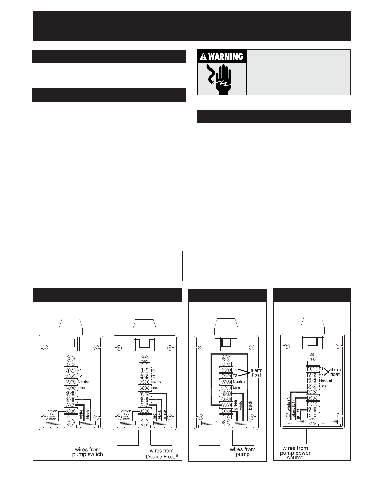
FIGURE C
Tank Alert®XT Indoor/Outdoor Alarm
Terminal Block Option Wiring Instructions
INSTALL THE FLOAT SWITCH AND ALARM
Follow Tank Alert®XT Indoor/Outdoor Alarm Installa-
tion Instructions included.
INSTALL THE PUMP SWITCH
NOTE: Electrical rating of pump must not exceed 20
amps at 120 VAC or 20 amps at 230 VAC.
1. Followmountinginstructionsincludedwithpump
switch.
2. Determine the type of pump switch to be installed.
Select the installation diagram from FigureAthat
corresponds to the type of pump switch being
installed. Runwires from pump switch through
conduit as shown in FigureA:
Two-Wire Pump Switch Wiring: Using positions on
the right side of the terminal block, connect the black
wire to position 6, the white wire to position 7 as
showninFigureA(leftdiagram).
Double Float®Wiring: Using positions on the right
side of the terminal block, connect the black wire to
position 6, the white wire to position 5, the red wire to
position 7 as shown in FigureA(right diagram).
INSTALL THE PUMP
1. Runwiresfrompumpthroughthe same conduit as
the pump switch wiring as shown in Figure B.
2. On the left side of the terminal block, connect the
black wire to position 7, and on the right side of the
terminal, connect the white wire to position 5, and
the green wire to position 8 as shown in Figure B.
3. Runwiresfrompumppowersource through
conduit as shown in Figure C. This source should be
onaseparatecircuitfromalarmpower.
4. Using positions on the left side of the terminal
block, connect the white wire to terminal position 5,
the black wire to terminal position 6, and the green
wire to terminal position 8 as shown in Figure C.
5. Turn power on and tip pump switch to check
installation.Turnpoweroff.
6. Finish installing alarm panel according to Tank
Alert®XTInstallationInstructions.
NOTE:Routepumppower and alarm powercords
throughconduit on left. Route controlswitch, pump
switch, and pump cords through conduit on right.
ELECTRICAL SHOCK HAZARD
Disconnect power before installing or servicing
this product. A qualified service person must
install and service this product according to
national and local electrial codes. Do not
install in hazardous locations as defined by
theNational Electrical Code,ANSI/NFPA70.
2-WIRE
PUMP SWITCH
FIGURE A
DOUBLEFLOAT®
PUMP SWITCH
OR
FIGURE B
WIRE SIZE 12-24 AWG WIRE SIZE 12-24AWG
WIRE SIZE 12-24 AWG

Inst.Instr.PN1011020G
©SJE-Rhombus Rev 04/08
NOTES: _______________________________________________________________________________________________
_______________________________________________________________________________________________________
_______________________________________________________________________________________________________
_______________________________________________________________________________________________________
_______________________________________________________________________________________________________
_______________________________________________________________________________________________________
_______________________________________________________________________________________________________
_______________________________________________________________________________________________________
_______________________________________________________________________________________________________
_______________________________________________________________________________________________________
_______________________________________________________________________________________________________
_______________________________________________________________________________________________________
_______________________________________________________________________________________________________
_______________________________________________________________________________________________________
_______________________________________________________________________________________________________
_______________________________________________________________________________________________________
_______________________________________________________________________________________________________
_______________________________________________________________________________________________________
_______________________________________________________________________________________________________
_______________________________________________________________________________________________________
_______________________________________________________________________________________________________
_______________________________________________________________________________________________________
_______________________________________________________________________________________________________
_______________________________________________________________________________________________________
_______________________________________________________________________________________________________
_______________________________________________________________________________________________________
_______________________________________________________________________________________________________
_______________________________________________________________________________________________________
22650 County Highway 6
P.O. Box 1708
Detroit Lakes, Minnesota 56502 USA
1-888-DIAL-SJE (1-888-342-5753)
Phone: 218-847-1317
Fax: 218-847-4617
Other SJE Rhombus Security System manuals

SJE Rhombus
SJE Rhombus Tank Alert I User manual

SJE Rhombus
SJE Rhombus Xpert Alert User manual

SJE Rhombus
SJE Rhombus TANK ALERT AB User manual

SJE Rhombus
SJE Rhombus Xpert Alert RF User manual

SJE Rhombus
SJE Rhombus TANK ALERT EZ 120 VAC User manual

SJE Rhombus
SJE Rhombus MYSPY User manual

SJE Rhombus
SJE Rhombus TANK ALERT SOLAR User manual

SJE Rhombus
SJE Rhombus Xpert Alert User manual

SJE Rhombus
SJE Rhombus Tank Alert User manual


