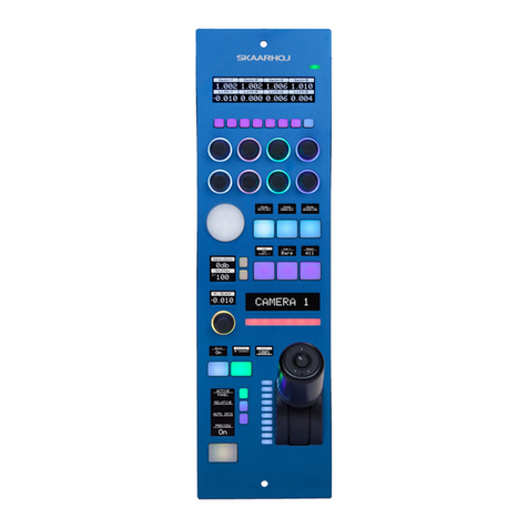
SKAARHOJ Blue Pill User manual

Contents
Contents 2
Important Information 4
Legal Notice 4
Warnings 4
Maintenance Precautions 4
Regulatory Compliance 4
Overview 5
Features 5
Controller Diagram 6
Color Fly v2 Top 6
Color Fly v2 Backside 7
Blue Pill Port Sides 7
System Configuration 8
Connection 8
Power 8
Network Recommendations 9
Power over Ethernet (PoE) Specifications 9
Accessing Blue Pill 9
DHCP or Static IP 9
Wi-Fi Access Point 10
Link from SKAARHOJ Firmware Updater 10
SKAARHOJ Firmware Updater and Micro USB 11
Adding Panels 11
Auto Discover 12
Manually Added 12
Panel Details 12
Confirm Connection 13
Select Mapping 14
Adding Devices 14
Auto Discover 14
Manually Added 15
Device Details 15
Populate Constant Sets 16
Connecting UniSketch Controllers 17
Blue Pill Mode - Via Serial monitor 17
Blue Pill Mode - Via Special Key 18
Fixed Configuration 18
Controller Use 20
Color Fly v2 20
2

Important Information
Legal Notice
Attention:
The content and instructions of this document are
subject to change without prior notice. Updates
will be added to the manual.
Best effort have been conducted to verify the
correctness of the content in this manual, but no
statement, information, or recommendation in this
manual shall constitute formal guarantee of any
kind, expressed or implied. We shall not be held
responsible for any technical or typographical
error in this manual.
The product and graphic appearance
demonstrated in this manual is for reference only,
and may differ from the actual appearance of your
device and associated software applications.
Use of this manual and the subsequent result shall
be entirely on the user’s own responsibility.
Reference to product names of other companies
in this manual are the trademark or registered
trademark of the respective companies.
Warnings
•If the product does not work properly,
please contact your dealer. Never attempt
to disassemble the controller yourself (we
will not assume any responsibility for
problems caused by unauthorized repair
or maintenance)
•This installation should be made by a
qualified service person and should
conform to all the local codes
•When shipping, the controller should be
packed in its original packaging
•Make sure the power supply voltage is
correct before using the controller
•Do not drop the controller or subject it to
physical shock
Maintenance Precautions
•If there is dust on the controller and the
displays, remove the dust gently using a
oil-free brush or dust blowing apparatus
•Do not use organic solvents, such as
benzene or ethanol when cleaning the
surface of the controller
Regulatory Compliance
For private households: Information on
Disposal for Users of WEEE
This symbol on the product(s)
and / or accompanying documents
means that used electrical and
electronic equipment (WEEE)
should not be mixed with general
household waste. For proper
treatment, recovery and recycling, please take this
product(s) to designated collection points where
it will be accepted free of charge.
Alternatively, in some countries, you may be able
to return your products to your local retailer upon
purchase of an equivalent new product.
Disposing of this product correctly will help save
valuable resources and prevent any potential
negative effects on human health and the
environment, which could otherwise arise from
inappropriate waste handling.
Please contact your local authority for further
details of your nearest designated collection
point.
Penalties may be applicable for incorrect disposal
of this waste, in accordance with you national
legislation.
For professional users in the European Union
If you wish to discard electrical and electronic
equipment (EEE), please contact your dealer or
supplier for further information.
For disposal in countries outside of the
European Union
This symbol is only valid in the European Union
(EU). If you wish to discard this product please
contact your local authorities or dealer and ask for
the correct method of disposal.
4
Figure 1

Overview
This user guide is suitable for the following
models
-Color Fly v2 using a Blue Pill with RED default
configuration
Features
•Support for RED Protocol including
•Focus
•Iris
•Color Offset Red/Blue/Green
•White Balance
•Auto White Balance
•Color Temperature
•ISO
•Shutter Speed
•Shutter Mode
•Power (Gain) Red/Blue/Green
•Color Saturation
•Slope Red/Blue/Green
•Tint
•Display Preset
•Highlight Roll-Off
•Paint Preset
•Record Start/Stop
•Audio Source
•Audio Gain
•Super crisp window with large display tiles for
settings
•High-quality encoders with RGB backlight for
function identification
•Camera ID display with OLED technology
•Four-way buttons with OLED legends for
dynamic labelling and functionality
•Motorized iris faders
•Power: DC 12V, 5W-30W PoE (+)
•PoE Standard: IEEE 802.3af/t
•Firmware Upgrade via networked connection
•DB9 (EXT I/O) connector
•Option for changing configuration layout
5

Controller Diagram
Color Fly v2 Top
1. 4 rotary encoders with RGB backlight and OLED displays for function identification
2. 4 rotary encoders with RGB backlight and OLED displays for future variable function
3. Variable function control
4. 4 motorized faders for Iris control
5. Menu navigation buttons
6. Camera select and panel lock buttons
6

Color Fly v2 Backside
1. Micro USB Port for serial communication with SKAARHOJ Firmware Updater
2. IP Network RJ45 Port for IP Control and PoE Standard: IEEE 802.3af
3. Status LED for monitoring and debugging
4. Reset, use only under the guidance of SKAARHOJ support
5. Config Button, to enable WiFi Access Point
6. 12V DC Power Supply, connect the supplied DC Power adaptor
Blue Pill Port Sides
1. USB-A Port. See Blue Pill/Reactor Manual for additional information
2. SKAARHOJ Expansion Slot. See Blue Pill/Reactor Manual for additional information.
3. HDMI Port for Image Grabber. See Blue Pill/Reactor Manual for addition information.
4. Config Button to enable WiFi Access Point. See Accessing Blue Pill section
5. Status LED for monitoring and debugging
6. IP Network RJ45 Port for IP control and 5W-30W PoE(+)/PoE Standard: IEEE 802.3af/t
7. Micro USB Port for serial communication and 5V power
7

System Configuration
Connection
The SKAARHOJ Blue Pill communicates to
camera(s) and the SKAARHOJ controllers via a
networked IP connection. For the RED cameras
this can be via WiFi connection in the camera to
the network or RED’s USB-C adaptor to ethernet
adaptor is needed for the Komodo, the V-Raptor
has it built in.
The layout of the configuration for the Color Fly is
done towards control of multiple cameras in
groups of 4. No video signal processing is done
on the SKAARHOJ RCP Pro.
Power
•Use only the DC power adapter supplied with the controller. Do not use any other DC power
adaptor
•The Blue Pill can be used with a PoE switch providing 5W-30W PoE (+)/PoE Standard: IEEE 802.3af/t
•The UniSketch controllers can be used with a PoE switch providing PoE Standard: IEEE 802.3af
•Ensure the PoE provider has sufficient power budget to power the controller. Otherwise it will not
function properly
8

Network Recommendations
•SKAARHOJ controllers have a 100 mbps network interface
•Network switch must have Auto-MDI/MDIX
•Network switch must support 100 mbps
•PoE: IEEE 802.3af
•SKAARHOJ controllers only support Half Duplex mode without Auto-Negotiate
Remember a SKAARHOJ controller and client must be on the same subnet (192.168.10.* or one defined
for the local network used by the controller). With multiple SKAARHOJ units connected to the same
network they need to have different IP addresses!
Power over Ethernet (PoE) Specifications
We use the PoE industry standard 5W-30W PoE (+) IEEE802.3af/t. To power our controllers using PoE it is
important the switch supports this standard. Please notice some manufactures such as Ubiquity have their
own non-standard 24V type of PoE which is incompatible with our controllers. Especially pay attention to
the standard when using a PoE injector.
Accessing Blue Pill
DHCP or Static IP
The Blue Pill’s user interface is accessed via the device’s IP Address and any web browser. The IP address
can be found on the display after it is plugged into a network connection with PoE or a network
connection and a power supply (5V Micro USB).
Entering the IP address into the address bar of a search engine will bring up a prompt for username and
password. The default is username: admin password: skaarhoj
9

Wi-Fi Access Point
If the Blue Pill is not displaying an IP address, the web interface is accessible by enabling the internal Wi-Fi
access point.
To enable the Wi-Fi access point, gently press and hold the config button on the side of the Blue Pill for
about 3 seconds (Found next to the Ethernet jack. Use a flat screw driver, a paper clip or similar). When
released, it will enable the internal Access Point and the LED will light up purple. It will show up in the Wi-
Fi networks list as SKAARHOJ-XXXXXX (Blue Pill’s serial number).
The default password is: skaarhoj
The web interface is then accessed at the IP address: 192.168.4.1
After accessing the Blue Pill it is best to navigate to the System Menu/System page to set a static IP
address. Once saved, the new IP address will appear on the Blue Pill’s display, it may be necessary to
reboot or power cycle the device afterwards.
Link from SKAARHOJ Firmware Updater
If the SKAARHOJ Firmware Updater open on a computer running on the same subnet as the Blue Pill, the
Blue Pill should appear below the main controller access buttons of the updater. Clicking on Configure
next to the panel’s information will open the web interface directly. The Blue Pill does not need to be
connected to the computer via USB.
10

SKAARHOJ Firmware Updater and Micro USB
If a network connection to the Blue Pill in not available, the IP address can be set using a Micro USB cable.
In this case the Blue Pill will appear in the “Select Device” dropdown and the “IP Config” tab in the
Firmware Updater can be used to set the IP address (same procedure from UniSketch):
In this case it was identified as “/dev/tty.usbmodem4430361” (on MacOS) and pressing IP Config will
open the IP set up page:
If/When the warning below appears, press “Submit” and reboot the Blue Pill:
Adding Panels
There are two ways a panel can be added, Auto Discover and Manually.
11

Auto Discover
Panels can easily be discovered by mDNS look ups on the same subnet the Blue Pill is on. This makes it
very easy to discover and include a panel in the configuration. mDNS will usually search the current
subnet, but with a correctly configured Blue Pill, panels on other subnets can easily be included too as
long as the IP and port is known to the user.
Pressing SHIFT + the green Select button will allow for multiple panel selection.
Manually Added
Panels can be picked from SKAARHOJs included library of products. Following a manual choice of panel,
the user will have to enter the IP address himself including any constraints desired. See the Panel Details
section for set up.
Panel Details
Panels have their status displayed clearly in the overviews on the Home screen.
There is a button for panel identification which can be used to light up the panel temporarily. This is very
useful with large collections of panels.
12

Clicking on a panel name in the Panels section will open up the details. Here the name, ID number, and
Active status of the panel can be changed. By default the controller name will be the same as the model
name, the ID will be auto generated in order, and the status will be active. A controller’s status needs to be
active for use.
Constraints are requirements regarding the panel. Here it is determined which specific controller is
connected, based on model and IP/Port.
By default our controllers connect using port 9923. It is important to include the port number, separated
from the IP address by a colon (:), for example 192.168.50.236:9923
Confirm Connection
A panel that has established a connection with a blue pill will no longer display “Waiting for Blue Pill” or
“Waiting for Raw Panel”.
13

Select Mapping
The controller’s layout is determined by the Mapping. For the RED Color Fly integration, the Generic
mapping is all that is needed, though for some combinations of panel and device, there are specific
mappings.
The mapping is chosen in the drop down next to the panel. Please note, the Color Fly for RED Komodo
configuration is a more advanced dual camera mode configuration not described in this guide. This guide
only covers the mapping done using the Generic configuration.
Adding Devices
There are two main ways a device can be added to a new Blue Pill, Auto Discover and Manually.
Auto Discover
Searching on the network for devices will find many types by a combination of mDNS look-ups and other
methods. However, not all devices can be discovered easily, but with those that can, it’s a simple click of a
button to add it to the Blue Pill device collection. Following an Auto Discover some device details may still
be needed to establish connectivity. See Device Details section for set up.
Pressing SHIFT + the green Select button will allow for multiple device selection
14

Manually Added
If a device must be added manually, it’s easy to look it up in the list of supported models. Following a
manual choice of device, the user will have to enter the IP address and other possible device detail
information. See the Device Details section for set up.
Pressing SHIFT + the green Add Device button will allow for multiple device selection.
Device Details
Devices have their status displayed clearly in the overviews on the Home screen.
Clicking on a device name in the Devices section will open up the details. Here the name, ID number, and
Active status of the devices can be changed. By default the controller name will be the same as the model
name, the ID will be auto generated in order, and the status will be active. A controller’s status needs to be
active for use. When applicable to the device, the option for connecting is a specific Username and
Password will also be available. Without setting a specific username and password, in most cases the core
will try to connect to the device’s default username and password.
15

Populate Constant Sets
The final step is to fill in any constant sets. The constant sets are available based on the chosen
configuration and should contain entries such as specific cameras for a controller, or the inputs for a video
switcher etc. They are most common when working with PTZ cameras and routing panels, though may be
available for additional device configurations.
The setup tables will auto save and quickly appear on displays and enable the function.
An example of a setup table would be a camera selector and can be seen below. These can be different
depending on the selected configuration. From here the order on the camera selector row of the panel
will be set as well as the desired name on the displays.
16
Column
Description
Order
Allows for quick rearranging of camera order. Right clicking on drag will allow for deleting the row.
Mute
Allows for removing access to a specific camera or to leave a blank spot on the panel
Binding
Allows for the selecting of a specific connected camera
Device Number
Ties the camera selector to the specific device. This is found in the Devices section. Each device will have a
unique device number per device core. This box should auto-populate when a camera is selected in binding
Camera Name
Customizable name to appear on the displays. Character limit is determined by size of display and can vary.
Device
Configuration
Selects the protocol based configuration associated with camera. Needed protocol can be seen in the
Devices section, each device is grouped into their native protocols. Double check the correct
configuration is selected. Improper selection will effect camera control.
Iris Channel Config
Selects the needed protocol for Iris/Master Black control. For cameras without a variable lens this will follow
the same protocol as the device. For cameras with a variable lens, select the protocol for the attached lens.
Tally Index
Tally Index number sets the input number to be reflected on the buttons. This is associated with the Tally
Forwarding constant set, see https://wiki.skaarhoj.com/ for more information. This column does not need
to be filled out for standard operation.
Route Index
Route Index number sets the input number to be reflected in the desired simultaneous route. This is
associated with the Routing Trigger constant set, see https://wiki.skaarhoj.com/ for more information. This
column does not need to be filled out for standard operation.
Color
Allows for the setting of a specific color to the camera select button.

Connecting UniSketch Controllers
The Blue Pill works as a wonderful add-on to connect and control UniSketch controllers like never before.
There are three ways to set a UniSketch controller to allow for connection to the Blue Pill. Two of the
methods will involve using the SKAARHOJ Firmware Updater available here: (https://www.skaarhoj.com/
support/firmware-updater). The controller will need to be connected to the computer by USB cable. After
the controller is set to Blue Pill Mode, it will no longer need USB connection for programming. This will be
done through the Blue Pill web interface.
Blue Pill Mode - Via Serial monitor
Starting with UniSketch v2.5.14, it is possible to put the panel into Blue Pill Mode with a command in the
serial monitor. Using this method the controller will be assigned an IP address only via DHCP.
To enter Blue Pill mode, type in: TakeTheBluePill in the serial monitor. The mode will be confirmed:
The IP address of the controller will now be confirmed in the boot up information for the controller:
The IP address will also be displayed on the panel along with “Waiting for Blue Pill”
An advantage of Blue Pill Mode is, that it will not destroy any existing configuration on the panel and can
easily be exited from again by writing “reset” or pressing the reset button in the serial monitor. Blue Pill
Mode is meant as a quick way to get in and out of Blue Pill Mode when using UniSketch panels in both
ways regularly.
17

Blue Pill Mode - Via Special Key
Blue Pill Mode can be enabled and disabled without the serial monitor on most UniSketch panels running
firmware version 2.5.14 and above.
•Enter Blue Pill Mode: During power-up, when the color animation first appears across the buttons,
press the button in the lower left corner of the controller twice. When the color animation completes,
it should sweep across the controller with just blue color - and it will reboot Blue Pill Mode
• Exit Blue Pill Mode: Same procedure as above. When Blue Pill Mode is exited, the color sweep to
confirm it will be white instead of blue.
The IP address will also be displayed on the panel along with “Waiting for Blue Pill” the same as when
using the serial monitor to enter Blue Pill Mode.
Fixed Configuration
If a static IP is needed it is possible to do so by selecting the default configuration called Blue Pill Mode
and loading it onto the controller. This uses our SKAARHOJ Raw Panel integration with the needed device
core options already selected. We recommend this type of configuration for any static or long term
installation.
Once it has been selected the IP address can be set either in the Network Configurations section in the
Simple Configuration page before the firmware is loaded onto the controller via the Update
Configuration/Firmware button on the updater.
Or it can be set in the IP Config tab of the SKAARHOJ Firmware Updater.
18

Please note, in both methods, the IP address for the UniSketch Raw Panel device core does not need to be
set to a specific IP as it has been set to Server Mode and is being connected to and not connecting to
anything. Having it Enabled is enough.
The IP address will also be displayed on the panel along with “Waiting for Raw Panel
19

Controller Use
Color Fly v2
Overall the controller have eight menus. To change between the menus press M1-M6. The camera select
row is dynamic to the number of cameras connected
20
M1-M6
P1-P6
C1-C6
F1-F4
F1
Iris for C1
F2
Iris for C2
F3
Iris for C3
F4
Iris for C4
Page 1
Page 2
ENG Menu
M1
Home
Slope
Sleep
M2
Exposure
Audio
Reset Sleep
M3
Exposure 2
System
-
M4
Lift
-
-
M5
Power
-
-
M6
Menu Page
Menu Page
Expert Mode
C1
Panel Lock
C2-5
Camera Select
C6
Camera Page/
long press
opens ENG
Menu
Home
Exposure
Exposure 2
Lift
Power
Slope
Audio
System
ENG
Menu
K1
Exposure
Adjust
Exposure Adjust
Display Preset
Offset Red
Power Red
Slope Red
Audio
Source
Calibration
Sleep Time
K2
Shutter
Shutter Speed
(press=mode
toggle)
Highlight Roll-
off
Offset Green
Power Green
Slope
Green
Link L/R
Gain
Auto WB
Dim Tim
K3
Focus
Iris
Output Tone
Map
Offset Blue
Power Blue
Slope Blue
Audio Gain
Left
Record
Display
Brightness
K4
Color
Temperature
(press=mode
toggle)
Iso
Enable COL
Color
Temperature
(press=mode
toggle)
Color
Saturation
Tint
Audio Gain
Right
Focus
LED
Brightness
K5
-
-
-
-
-
-
-
-
K6
-
-
-
-
-
-
-
-
K7
-
-
-
-
-
-
-
-
K8
-
-
-
-
-
-
-
-
P1-5
Paint Presets
P6
Presets Page
K1-K5
Table of contents
Other SKAARHOJ Controllers manuals
Popular Controllers manuals by other brands

Velleman
Velleman HQ POWER VDPC174 user manual

Texas Instruments
Texas Instruments bq34z100 user guide

Grifco
Grifco E138G quick start guide

Siemens
Siemens SIRIUS 3RW40 5 Original operating instructions

D-Link
D-Link DWC-1000 user manual

Sentera Controls
Sentera Controls HPSPX-LP Mounting and operating instructions

RoboteQ
RoboteQ Dual Channel Digital Motor Controller AX2550 Quick start manual

Array electronic
Array electronic FAB2 Series user manual

Gas Detection
Gas Detection GDA 40125 operating manual

Sealey
Sealey POWER PRODUCTS SA206 instructions

TEControl
TEControl UNI MIDI Breath Controller user guide

Micronor
Micronor MR380-1 Series instruction manual