SKB CV212-14 User manual

“SKB Elektronmash”TDV
LINE SMOKE DETECTOR
CV212-14
User Manual
AKPI.425231.001RE

2
CONTENT
1
DESCRIPTION
4
1.1
APPOINTMENT
4
1.2
SPECIFICATIONS
5
2
INSTALLATION
6
3
OPERATION OF THE DETECTOR
8
4
CONNECTION AND COMISSIONING
11
5
INSPECTION FUNCTIONING
15
6
MAINTENANCE
16
APPENDIX A. General view and overall dimensions of the
transmitter and receiver
17
APPENDIX B. Transmitter and receiver mounting dimensions
18
APPENDIX C. Marking and connecting elements
19
CERTIFICATION INFORMATION
The line smoke detector CV212-14 is certified in accordance with the
requirements of the standard EN 54-12:2015 Fire detection and fire alarm systems.
Part 12: Smoke detectors. Line detectors using an optical light beam.
Quality Management System at the factory is certified in accordance with the
requirements of the standard ISO 9001.
Copies of certificates are on the site http://www.chelmash.com.ua
MANUFACTURER
“SKB Elektronmash”TDV
265B Golovna str.,
Chernivtsi,
Ukraine 58018
tel/fax (03722) 40639
e-mail:spau@chelmash.com.ua
http://www.chelmash.com.ua
Version 001en

3
The user manual is intended for studying the device, operation, install and
commissioning of the line smoke detector CV212-14.
The following conventions are used in this manual:
c.i.e. - control and indicating equipment;
IL - transmitter;
IR - infrared;
PDU-L - remote control unit;
PL - a receiver;
UPS - uninterrupted power supply.
1 DESCRIPTION
1.1 APPOINTMENT
Line smoke detector CV212-14 (hereinafter the detector) consists of a
receiver PL and a transmitter IL. To control the operation modes, the PDU-L remote
control unit is used.
Detection of the products of combustion is performed by controlling the level
of attenuation of the infrared beam between a transmitter IL and receiver PL
(hereinafter transmitter and a receiver, respectively).
The detector is designed to work with fire alarm and fire alarm devices in fire
alarm and fire extinguishing systems.
The detector is designed to detect combustion products in enclosed spaces,
indoors or in places that prevent moisture from entering it.
The installation locations for the detector defined according to the planning
information.
Installation should be performed by a specialist in compliance with safety
regulations.
The detector is not a source of danger for people or for protected material
values (including in emergency situations).
In accordance with EN 62471, “Photobiological Safety of Lamps and Lamp
Systems”, the linear smoke detector falls into the “Exempt Group”.

4
1.2 SPECIFICATIONS
Range of action, m, range "10-100" 10...100
range "1-15" 1...15
Settable thresholds, dB 1, 2, 3
(approximately 15, 30 and 45% absorption by smoke)
Response time in the mode "ALARM (FIRE)", s, no more than 30
Readiness time, s, no more than 10
Power disruption time to reset, s, not less than 1
Operating voltage of transmitter and receiver, VDC 18...30
The transmitter and receiver are insensitive to the polarity of the supply voltage
Operating current of transmitter or receiver, mA, up to 8
Receiver current in mode "ALARM", mA, not less than 18
The maximum switched voltage by contacts
“ALARM”, "FAULT", V 100
The maximum switched current by contacts
“ALARM”, "FAULT", A 0.15
Maximum resistance of closed contacts of relay “FAULT", Ohm 30
Operating distance of remote control, m from 1 to 20
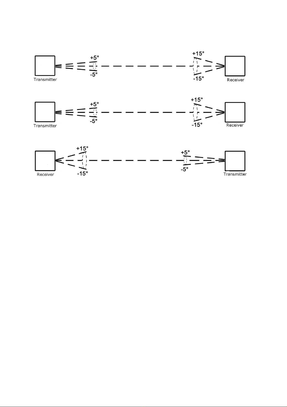
The deviation of the optical axis of the transmitter
relative to optical axis of the transmitter-receiver, degrees, not more than
during installation ±5
during operation ±2
The deviation of the optical axis of the receiver
relative to optical axis of the transmitter-receiver, degrees, not more than
during installation ±15
during operation ±2
Operating conditions of the transmitter, receiver:
Ambient air temperature, degrees Celsius from minus 5 to 40
Relative air humidity at 25°C, %, up to 98
Atmospheric pressure of air, kPa 84...107
Degree of protection of the detector and receiver shell IP40
Working position any
Working hours round-the-clock continuous
Service life, years 10

5
2 INSTALLATION
ATTENTION!
Detector components should be taken only beyond the side surfaces
of their bodies, avoiding touching the outer optical elements (filters).
A protective film with optical elements to remove the least
immediately before latching operation threshold on site.
2.1 The appearance and dimensions of the receiver and the transmitter are
shown in Appendix A.
2.2 Installation of transmitters and receivers should perform on fixed
structures and components of buildings on one optical axis towards each other.
The mounting surface for the detector’s components must be firm and
vibration-free. Metal supports that may be affected by heat or cold are unsuitable
for the installation.
Fastening base receiver and transmitter to the surface and perform two
fasteners (bolts, screws, dowels, not supplied) in accordance with Appendix B.
Pass the wires through the cable glands of the base (see Appendix A) and
connect them to the screw terminals of the connectors from the detector set.
Tighten the nut of the clamp of the seal only after passing all the wires.
It is possible to insert the wires from behind, for which it is allowed to drill the
holes of the correct size at the base of the detector components.
The side of the detector's receiver, on which the LED and the IR receiver of
the remote control is located, is deployed in the direction from which the LED and
the IR receiver of the detector's remote control are visible to the service personnel
(it is recommended to point downwards).
The side of the detector's transmitter, on which the LED is located, should be
deployed in the direction from which the LED of the transmitter is visible to the
service personnel (it is recommended to point downwards).
After installation, provide for measures to isolate the places of entry of wires
to protect against moisture, dust, penetration of insects.
2.3 Installation angle should comply with the maximum tolerances in any
planes relative to the optical axis of transmitter and receiver.

6
At installation, the maximum deviation in any direction from the central
optical axis should not exceed 5 degrees for transmitters and 15 degrees for
receivers as shown in Figure 1.
Figure 1
After fixing of a transmitter and receiver durable angular deviation from the
originally installed position should not exceed 2 degrees. This should be considered
when installing the detector components on structures that can deform with time.
2.4 The line of sight between the transmitter and the receiver always has to
be clear and may not be interfered by moving objects (e. g. overhead crane).
Heat accumulation under the roof may prevent smoke from rising up to the
ceiling. Thus, the detector must be mounted below the expected heat accumulation.
Since the smoke from a fire does not simply rise straight up, but rather
spreads like a mushroom cloud (depending on air current and accumulation), the
monitoring range is much greater than the diameter of the IR beam.
The maximum distance between two detectors with parallel IR beams is
determined by national standards. The minimum distance between the two
detectors is not regulated.
The centre line of the monitoring beam may not be closer than 0.25 m to
walls, ceilings, furniture or stored goods.

7
With a room height of more than 12 m, it is recommended to install a second
monitoring level on which the detectors are arranged offset to the first monitoring
level.
It is allowed to operate the detector through a glazed window or laminated
glass, with the angle between the normal to the base and the normal to the glass
should be more than 10 degrees.
The transmitter and the receiver are usually installed at the same height and
aligned with one another. The wide angle of view of the transmitter and receiver
allows for an easy installation and for a reliable long-term stability.
The detector must be mounted in a position where the receiver input window
is not exposed to direct sunlight or artificial light. Normal ambient light does not
affect the operation of the receiver.
3 OPERATION OF DETECTOR
3.1 Operation of transmitter IL
The transmitter operates continuously after power is applied and the
readiness time is complete. After the power is applied to confirm and verify the LED
itself, the transmitter gives one flash with duration of 1 second. The transmitter is
monitored by a green LED on its side, which should flash for a short time (0.25 s)
every 5 seconds.
3.2 Operation of receiver PL
The receiver operates continuously after power is applied and the readiness
time is complete. After the power is applied to confirm and verify the LED itself, the
receiver gives one flash with duration of 1 second.
The receiver outputs a signal "ALARM (FIRE)" by increasing the current
consumption and the "ALARM" output of the receiver is intended for the
transmission of an alarm signal by closing the contacts of the built-in relay (dry
contact; in the quiescent mode, the contacts are open).
The "FAULT" output of the receiver is intended for the transmission of a fault
signal by opening the contacts of the built-in relay (dry contact; in the quiescent
mode, the contacts are closed).
The states and indications of the transmitter IL and receiver PL are given in
Table 1.

8
A malfunction is one of the following:
high power voltage;
low power voltage;
the level of the light background exceeds the maximum allowed;
the level of interference exceeds the maximum allowed;
the signal level is higher than the allowable level;
the signal level is less than the allowable level.
Power and background malfunctions are reset automatically after the causes
have been eliminated, as well as from the remote control or power interruption; the
remaining faults can be cleared either by the remote control or by interrupting the
power.
3.3 Remote control unit PDU-L allows:
- set the test signal “ALARM-TEST” (button “3”)
- set the test signal "FAULT-TEST" (button “2”);
- cause the receiver to its initial state (reset) when a fault and/or the state of
the test fire (button “1”);
- set the thresholds for operation during memorization.
3.4 The test mode "ALARM-TEST" (set with the PDU-L) simulates the alarm
condition. This mode can be reset both with the PDU-L and the power supply of the
detector's receiver. The alarm on the working signal ("true fire") is reset only by
interrupting the power supply of the detector's receiver.
3.5 The test mode "FAULT-TEST" (set with the PDU-L) simulates the fault
condition. This mode can be reset both with the PDU-L and the power supply of the
detector's receiver.

9
Table 1
Current
consumption
of detector’s
receiver
-
no more 8 mA
no more 8 mA
Current
consumption
of detector’s
receiver
no more 8 mA
not less 18 mA
not less 18 mA
no more 8 mA
FAULT
contacts of
detector’s
receiver
open
open
closed
FAULT
contacts of
detector’s
receiver
closed
closed
closed
open
ALARM
contacts of
detector’s
receiver
open
open
ALARM
contacts of
detector’s
receiver
closed
closed
open
The status of the indication LEDs
on the receiver and on the transmitter
off
Double flashes approximately 1 time per second
Flashes every 5 seconds
At the transmitter of the detector - single.
At the detector's receiver:
Single - 1 dB threshold;
Double –2 dB threshold;
triple - 3 dB threshold.
The status of the indication LED
on the receiver
At the beginning of memorization, regular flashes
of about 25 seconds, then a pause of about
10 seconds, a total storage time of about
45 seconds, then three flashes with duration
1 second upon successful memorization. Errors of
memorization - double flashes with a weak signal.
Lights up continuously
Double flashes approximately 1 time per second
Condition of
receiver
off
FAULT
QUIESCENT
Condition of
receiver
REMEMBERING
ALARM
ALARM-TEST
FAULT-TEST
Power
off
on
on
Power
on
on
on
on

10
4 CONNECTION AND COMISSIONING
4.1 Connections
The connecting elements of the receiver and the transmitter are shown in
Appendix C. To the connectors (are included in the detector set) it is possible to
connect a wire with a cross-section from 0.2 to 1.5 square mm.
4.2 Transmitters connecting
The transmitter can be powered by an uninterrupted power supply of a
(21…30) VDC or from zone of c.i.e. (it is recommended for one transmitter in the
zone; it is allowed for two at a current limit of the zone of at least 25 mA). The
connection methods for both options are shown in Figure 2.
1 2 3 4 5
1 2 3 4 5
CODE
1 2 3 4 5
CODE
CODE "ZONE"
"ZONE"
to c. i. e.
АB
1 2 3 4 5
CODE
c. i. e.
"ZONE"
"ZONE"
transmitter 1
DISTANCE
DISTANCE
DISTANCE
"FAULT"
UPS
"10-100"
DISTANCE
"1-15"
"1-15"
"10-100"
"10-100"
"1-15"
"1-15"
"10-100"
transmitter n
transmitter 1
transmitter 2
zone
21...30 VDC
21...30 VDC
Figure 2
It is possible to connect several transmitters to a single UPS within the power
supply output current Iout (A); maximum number of transmitters n=80*Iout.
It is recommended to use UPS with the output "MALFUNCTION" for
monitoring the condition of the UPS.
The total resistance of the wires should not exceed 250/n ohms.
Transmitter’s green LED should briefly flash 1 time per 5 seconds.

11
4.3 Receivers connecting
Receivers are connected to the zones of c.i.e. only one at a time and transmit
the status of "ALARM (FIRE)" by increasing current consumption and closing the
“ALARM” contacts. Connection to the alarm loops is shown in Figure 3.
"ZONE" "ALARM"
"FAULT"
"ZONE"
"FAULT"
"FAULT"
"FAULT"
"ALARM"
zone n
c. i. e.
receiver 1
zone n+1
zone 1
receiver n
Figure 3
The total resistance of the wires should not exceed 250/n ohms.
The output "ALARM (FIRE)" is galvanically isolated (dry contact). In the
quiescent mode (as well as "FAULT" and "FAULT-TEST") contacts are open, in the
“ALARM (FIRE)”, “ALARM-TEST” modes contacts are closed.
When using the "ALARM" outputs, each of them is connected to one alarm
loop in accordance with the description for the device used.
Alternative option is to connect the outputs "ALARM" of all receivers to one
zone with current-limiting resistors RLIM at the every receiver and terminating
resistor RT on the farthest receiver (Figure 4). In this case, the alarms on all the
connected receivers will be processed by OR, that is, if it is alarm at least in one

12
receiver which is connected, a common signal is alarm. If it is no alarm at all
receivers that loop current will be limited by the terminating resistor RT and wire
resistance and zone to be normal. In this case it is possible to connect all receivers
to the power supply within the power supply output current Iout (A); maximum
number of receivers n=80*Iout.
zone
Figure 4
The output "FAULT" is galvanically isolated (dry contact). In the quiescent
mode (as well as "ALARM (FIRE)" and "TEST FIRE") contacts are closed, in the
“FAULT”, “FAULT-TEST” modes contacts are open.
The output "FAULT" is connected to the zone (zone n+1 in the Figure 3)
through the current-limiting resistor RLIM and in case of a fault, this loop is set to
an open.
It is possible to connect the outputs "FAULT" of all receivers to one zone in
series with a current-limiting resistor at the farthest receiver (as in Figure 3). In
this case, the faults on all the connected receivers will be processed by OR, that is,
if it is faulty at least in one receiver which is connected, a common signal is faulty
and will in breakage. If it is no fault at all receivers that loop current will be limited
by the load resistor set (RLIM in Figure 3) and wire resistance and zone to be
normal.
The total resistance of the wires used to connect "FAULT" outputs, should not
be in place with the current-limiting resistor exceed resistance limiting current
standards for the zone.
If it is necessary to distinguish between the break of the loop and the
malfunction of the receivers and monitor the condition of the actual fault zone, the

13
connection diagram should correspond to Figure 5, where RSHUNT is a shunt
resistor, RT is a terminating resistor.
zone
Figure 5
In this case, termination of the zone wires will give a fault in this zone in the
c.i.e., and the failure of the receiver will give an alarm in this zone.
Calculation of the values of the resistors is made according to the
documentation for the instruments used.
4.3 Comissioning
4.3.1 When the distance between the transmitter and receiver less than
12 m, jumper "1-15/10-100" on the transmitter should be set to the position "1-15"
(see Appendix B). If the distance is more than 10-12 m, set the jumper to the "10-
100" position.
4.3.2 When used in the same room more than one linear detector must be on
adjacent transmitter and detector zones it set different codes jumper setting
(Jumpers) on the "CODE" fork contacts in accordance with Table 2 and Appendix C.
Table 2
Jumper
on contacts
1 and
2
2 and
3
3 and
4
4 and
5
5 and
6
Not installed
Code
1
2
3
4
5
6
4.3.3 Remembering (setting detector in working condition)
4.3.3.1 Power on the transmitter (it is possible to supply power to the
entire transmitters, installed in this room, simultaneously). Supply power only to
the receiver, with which the work is directly performed, the receivers of all other
detectors should be turned off. This is necessary to prevent changes in the settings
of receivers, with which the work is currently not carried out.

14
After applying power to the receiver, wait for about 10 s. The red LED on the
receiver should flash with a short single pulse with a period of 5 s (in the delivered
state).
4.3.3.2 Press the "F/C" button on the PDU-L - the red LED of the remote
will go in the double's treatment outbreaks (mode is active 8 s).
Send remote control PDU-L to the remote control IR receiver at the detector
receiver and by pressing the corresponding button set the threshold detector
according to the draft (1 dB - button "1", 2 dB - button "2", 3 dB - button "3").
Recommended values the thresholds depending on the working distance are
1 dB at a distance of up to 20 m, 2 dB at a distance of 20 to 40 m, and 3 dB at a
distance of more than 40 m.
If the memory is successfully completed, the red LED should give 3 flashes
with a duration of 1 second every. The detector is ready for operation.
If an error of remembering that may occur if:
- background level exceeds the maximum allowed;
- supply voltage does not correspond to a nominal value;
- the level of interference exceeds the maximum allowed;
- the signal strength is less or more than the allowable value
the red LED should go into the dual flash mode with a repetition period of about
1 s, indicating a malfunction.
It is necessary to eliminate the factors that prevent the memorization -
control distance between the transmitter and receiver and the jumper on the
transmitter in the appropriate position, to ensure absence and obstacles
overlapping their line of sight between the transmitter and receiver or presence
reflective (specular) surfaces near the optical axis between transmitter and
receiver.
After elimination the detected reasons, repeat the memorization with the
desired threshold.
If the memorizing is successful, the detector goes into standby mode, and by
specifying the set threshold for the number of flashes with a period of 5 seconds
(see Table 1).

15
5 INSPECTION FUNCTIONING
5.1 The functioning of the detector receiver can be checked without
connecting it to the system. To do this, it is necessary to apply the supply voltage
to the terminals "ZONE" receiver (constant voltage 18...30 VDC.
Press "3" button on PDU-L - receiver should go into a state of "ALARM (FIRE)"
(see Table 1), and red LED of a receiver must continuously shining.
Post a receiver command "RESET" by pressing the button "1" on the remote
control PDU-L.
The receiver’s red LED should go out.
5.2 Checking the alarm system
The detector and the system must stand on quiescent condition.
Press button "3" on the remote control PDU-L - receiver should go into a state
of "ALARM (FIRE)" (the test), the red LED on the receiver must continuously shine.
The system must switch over to the "ALARM (FIRE)" in a zone, which is connected
to the detector.
Reset fire on the c.i.e. The fire alarm system and the detector should be in
the quiescent condition.
5.3 Signal check on signal
Cut off half of the input filter of the receiver with an opaque flap of any
material. The receiver and the system must go to the "ALARM (FIRE)" state in the
zone to which this detector is connected.
Reset the fire at the c.i.e. The fire alarm system and the detector should be in
the quiescent condition.
5.4 Check for a fault signal
Cut off entire receiver by a shield of any opaque material. The receiver must
go into fault mode (see Table 1).

16
6 MAINTENANCE
Service should be conducted at least once every six months with the
detectors disconnected, so as not to cause false alarms.
Service consists in removing dust and dirt from the filters and housings on
the transmitter and receiver. Cleaning optical surfaces should be done with a soft,
lint-free cloth moistened in water (if contamination of optical surfaces is not
removed by a damp cloth).
ATTENTION! Do not use acetone-containing liquids and other solvents
that can damage the surfaces of optical elements.

17
APPENDIX A
General view and overall dimensions of the transmitter and receiver

18
APPENDIX B
Transmitter and receiver mounting dimensions

19
APPENDIX C
Marking and connecting elements (cable glands are not shown)
Transmitter IL (position of jumpers is shown conditionally)
Receiver PL

20
MANUFACTURER
“SKB Elektronmash” TDV
Golovna str., 265B,
Chernivtsi,
Ukraine 58018
tel/fax (03722) 40639
e-mail:spau@chelmash.com.ua
http://www.chelmash.com.ua
Version 001en
Table of contents
Popular Smoke Alarm manuals by other brands

Zeta
Zeta ZD-SI-610/ZD-SO-610 user manual

UniPOS
UniPOS FD 7130 instruction manual

Kidde
Kidde DY29 Installation instruction

System Sensor
System Sensor 2100TR Installation and maintenance instructions

System Sensor
System Sensor 2151 Installation and maintenance instructions

VESDA
VESDA LaserSCANNER VLS-200 installation manual