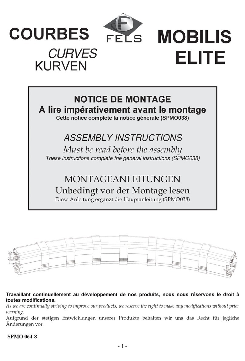
Fels Mobilis ELITE User manual


Sommaire
Introduction
Sélection du produit 6
Calcul de ligne 10
Mobilis Elite
Présentation 17
Données techniques 20
Composants 31
Standard straight element 31
High temperature straight element 34
Straight element without earth marking 37
Straight element with protection lips 41
Covering flange 44
End-cap 47
Sliding hanger 49
Fixed hanger 52
Bracket 55
End-line feed 58
M25-M32 in-line feed 62
M40 in-line feed 67
Pre -mounted feed box on straight element 72
Introduction gate 76
Ventilation element 79
Expansion joint 82
Horizontal curve 87
www.fels.fr | T +33(0)3 88 67 10 60 | F +33 (0)3 88 55 01 79 | Edité le 04/01/2017 Page 2/223

Transfer elements 90
Circuit interruption element 94
Rigid trolleys 97
Simplified trolleys 103
Articulated trolley 107
Special trolley for transfer element 112
High speed trolley 116
Cleaning trolley 121
Standard carrier 124
Carrier with box 127
Special carrier for long transfer element 131
Switching finger 134
Set of 5 screws + nuts 20A - 100A 136
Set of feed connection for 5th pole 137
Set of 10 screws + 5 nuts 130A 138
Set of connection screws 160A 139
Set of connections for 200A 5 poles 140
Set of connection screws 200A 141
Set of 4 collector brushes 142
Set of 5 collector brushes 143
Brush for simplified trolley 144
Set of 5 cleaning brushes 145
Set of 2 special screws for fixed hangers 146
Set of 2 carrier rings 147
Cone for short transfer element 148
Cone for long transfer element 149
Mobilis Movit
Présentation {††††‱㔱
}
www.fels.fr | T +33(0)3 88 67 10 60 | F +33 (0)3 88 55 01 79 | Edité le 04/01/2017 Page 3/223

Données techniques {††††‱㔴
}
Composants {††††‱㘱
}
Rail 161
Connection 165
Covering flange 168
Feeding box 171
End-cap 175
Sliding hanger 178
Fixing clamp 182
Collector 186
Collector bracket 191
Bracket 194
Expansion joint 197
Circuit interruption element 200
Cable eye stiffeners for feed 203
Brush for preparation of rail ends 204
Contact lubricant 205
Replacement brush for collector 206
Single cleaning collector 207
Cleaning and grindding brushes 209
Kit for unclipping sliding hangers 210
Ice shield 211
Gammes historiques
Composants {††††′ㄳ
}
Mobilis Elite 200A non -reduced Earth 213
Obsolete range MOBILIS CE 216
www.fels.fr | T +33(0)3 88 67 10 60 | F +33 (0)3 88 55 01 79 | Edité le 04/01/2017 Page 4/223

Trolley with cable Mobilis CE 217
Standard brushes for carriage mobilis CE 218
Brushes of trolleys mobilis CE for lines with transfer element 219
Remote control brush Mobilis CE 220
Obsolete range MOBILIS UNIT 221
Brush for pantograph 100A Mobilis UNIT 222
www.fels.fr | T +33(0)3 88 67 10 60 | F +33 (0)3 88 55 01 79 | Edité le 04/01/2017 Page 5/223

RELIABILITY, SAFETY, EASY USE, HIGH
PERFORMANCE
… right out of the box!
Pages of product selection .
OUTSTANDING ADVANTAGES:
Quick and easy installation of Movit and Elite
Tried and tested safety ensured
Reduced maintenance and exceptional operating life
Tried and tested reliability
No expansion issues
Product selection
Modular elements available in several lengths
Pre-assembled hangers
Clipped-on mounting of lines in self-aligning hangers
Safe and easy Elite connection by self-breaking screws guaranteeing tightening at optimum torque
Large number of accessories quickly mounted, with no special tool
All accessories are pre-assembled in the factory
Current collector brushes of Elite, removable without uninstalling collector wiring
Dust protection lips of Elite, pre-mounted in the factory for time saving on the site
Elite rails with safety pins for direction and intensity
Wear parts size specially designed for long maintenance-free operating life
Sturdy design , tried and tested over 40 years
Sturdy and tried and tested design of Elite and Movit
Light-weight and more rigid cellular structure of Elite
Qualification
and
endurance
testing
to
requirements
stricter
than
standards
before
placing
on
the
market
Issues of expansion differences in materials considered early at the design stage
Long lengths of line with no expansion joint needed
Expansion joints of innovative and compact design
Complies with international standards (EN60204-32, CEI61439-6)
Elite and Movit have IP23 protection index, which means that the equipment is protected so that
people cannot access the dangerous sections, even under the rain
Thousands of applications made safe by Mobilis worldwide over many years
www.fels.fr | T +33(0)3 88 67 10 60 | F +33 (0)3 88 55 01 79 | Edité le 04/01/2017 Page 6/223

Developed to meet the needs on the field
Ancillary costs reduced
Long lengths of line feasible
1. PRESENTATION
Multi-conductor Rail Single-conductor Rail
Mobilis ELITE:
Quick installation:
Multiple pole lines with 4 or 5 pre-mounted
conductors and many accessories to clip-on (no
tools required)
Quick and easy connection:
Connection system with built-in self-breaking
screws, guaranteeing tightening at optimum torque
Reduced voltage drop at connections:
The very large exchange surface, and tightening
maintained at optimum torque allow reducing and
controlling voltage drop
Excellent safety and operator protection:
The closed profile of the mounted line with the full
set of accessories has a protection level of IP23,
which means that the equipment is protected so
that people cannot access the dangerous
sections, even under the rain
Operating reliability: The current collectors, tested
against requirements stricter than the standards,
are designed to run for several thousand
kilometers, providing reduced maintenance of
facilities
Product selection
Mobilis MOVIT:
High speeds:
Up to 600m/min
High currents:
Up to 630A
High mechanical resistance:
H rigid profile and sturdy accessories, ideal
where reliability, safety, and high performance
are required
Optimized contact:
Collector contact under control due to
provision for angular offset
Cost-effective modular system: replacement of one element/quick and easy extension
Quick and easy mounting
Quick customer help and decision with the Online Quote and Design Tool
CAD 2D/3D File Package made available to reduce design & installation costs
Unlimited lengths of line due to expansion joints
Vitesse élevée
Mobilis ELITE ®
Mobilis MOVIT ®
Special accessories available to meet field requirements (ventilation elements, circuit
interruption, inlet gate, maintenance devices)
Vertical and horizontal curves
Elements for transfer
Easy assembly of ergonomic range: quick and intuitive to learn, visual assembly instructions on
rail for Elite
Materials suitable for the various industrial environments
Voir les composants
Movit
Quick installation
Quick and easy connection
Reduced voltage drop at
connections
Excellent safety and
operator protection
Optimized contacts
High mechanical resistance
High speeds
Operating reliability
High currents
www.fels.fr | T +33(0)3 88 67 10 60 | F +33 (0)3 88 55 01 79 | Edité le 04/01/2017 Page 7/223

Number of poles: 4 or 5 Number of poles: 1 to infinity
Intensities: 12A, 20A, 40A, 60A, Intensities: 315A,
100A, 160A, 200A 450A, 630A
Maximum operating voltage: 750V Maximum operating voltage: 750V
Protection Index IP23 according to EN60529 Protection Index IP23 according to EN60529
Complies with Standards EN60439-2, Complies with Standards EN60439-2,
EN60204-32, CEI61439-6 EN60204-32, CEI61439-6
INTRODUCTION :
As a specialist of electrical supply rail manufacturing for mobile equipment since the seventies, the
FELS Company has perfect knowledge and experience of the needs of the integrators, installers,
and end-users on this market worldwide, and of the special features of such devices. Its two
product ranges, MOBILIS Elite and Mobilis Movit have been designed to meet the requirements of
international standards. They offer a long operating life due to their robustness, with wear parts
strengthened to reduce maintenance of facilities. The high quality of materials and the great care
used for their workmanship also guarantee a long service life.
The high performance level achieved by all the ranges of rails results of the close contacts that
Fels has maintained over the years with the many manufacturers, installers, and end-users of such
equipment.
CLIENT SERVICE:
In order to meet the increasing demand for services on the part of its clients, Fels has developed a
capacity for listening and quick reaction within its organization. Each client is provided with
permanent and personalized assistance and follow-up. We insist on maintaining close contact, in
order to make the commercial and technical transactions, as much productive as possible, and
leading to improved quality in the interest of both parties. Service quality is indeed recognized by
clients as one of our main advantage.
A BROAD RANGE OF REFERENCES:
Since it was launched, the Mobilis Elite electric rail has proved its efficiency in all sectors where
top-quality mobile electrification is required. Fels has supplied its equipment to customers in
myriad plants throughout Europe and the world, proving that this leading-edge equipment can be
adapted to many applications: the car industry, aeronautics industry, chemicals, railways and
energy industries –everywhere where travelling cranes are essential.
With its network of partners, selected because they share the Fels philosophy in terms of quality
and service, Fels has broken into the market on all five continents, providing and efficient, reliable
service for companies in all sectors. When it comes to services, Fels also supplies the energy right
down the line !
2. DATA NEEDED TO SELECT EQUIPMENT
The following data must be known in order to define the intensity of a MOBILIS line:
Selection of product
www.fels.fr | T +33(0)3 88 67 10 60 | F +33 (0)3 88 55 01 79 | Edité le 04/01/2017 Page 8/223

Maximum intensity in continuous operation, or failing this power and types of receivers (cage
or slip-ring motors, electronic starters, resistors)
Receiver start-up intensity
Maximum ambient temperature
Maximum clearance between a receiver and the nearest feeding point
Permissible voltage and voltage drop in continuous operation and on start-up
Type of current (frequency, voltage)
Running cycle of the receiver (duty cycle, or operating time per 10-minute cycle).
In addition, review the following options to find out the most appropriate solution:
Installation with more than 5 conductors: select Mobilis Movit or arrange 2 Elite lines in parallel
Installations with curves and a radius shorter than 15m, or transfers between different circuits:
select Mobilis Elite
Installations with mobile speed greater than 180m/min: choose Mobilis Movit
For all other configurations, calculate intensity to select the best equipment.
All the above features along with the calculation of intensity (see below) will help you determine
which range is most appropriate to your needs, Elite 12A-200A Range or Movit 315A-630A Range,
The first selection criteria to be considered being the permissible current for Mobilis rails, which
must be higher than the installation intensity, and the second criteria being the voltage drop
involved.
You may also use the Online Calculation Tool on our website: www.fels.fr
The details above can also be used to fill out the online Consultation Sheet for assistance by our
Engineering Office.
3. TECHNICAL DETAILS:
See Technical data of Elite Range
See Technical data of Movit Range
4. LINE CALCULATION:
See the section Line calculation
5. OBSOLETE EQUIPMENT
See the section Historical ranges
6. GUARANTEE
Our equipment is guaranteed one year against any material or manufacturing defect recognized by
ourselves. As we are not responsible for its installation and operation, our guarantee covers only
replacement or repair (at our own choosing) of the part recognized to be defective.
We do not accept responsibility for any defects arising from faulty supervision or maintenance. We
also disclaim liability for any production stoppages that may result. Any arbitration shall be held in
Strasbourg, even when several defendants are involved.
Selection of product
www.fels.fr | T +33(0)3 88 67 10 60 | F +33 (0)3 88 55 01 79 | Edité le 04/01/2017 Page 9/223

LINE CALCULATION
To set the product and the intensity of the MOBILIS ELITE line, two parameters must be considered
simultaneously:
The voltage drop on line, which must be below the permissible value
The product current capacity, which depends on the ambient temperature and on the duty
cycle factor.
The following data must be known:
• Maximum intensity in continuous operation
• Type of receivers (cage or slip-ring motors, electronic starters, resistors)
• Receiver start-up intensity
• Maximum ambient temperature
• Maximum distance between a receiver and the nearest feeding point
• Permissible voltage and voltage drop in continuous operation and at start-up
• Type of current
• Running cycle of the receiver (duty cycle)
You can find out immediately the most suitable intensity by connecting to our website www.fels.fr
and using our on-line "Mobilis Price Calculator".
For help in calculation by our Customer Service Department, fill out the Consultation Sheet.
For manual calculation, follow the procedure below.
1. INTENSITY IN CONTINUOUS OPERATION
Take into account the number of receivers which run simultaneously and calculate the
corresponding intensity:
IN= I1+ I2+ … + In
The intensity may be worked out from the power of the receivers.
In a three-phase system, this gives:
Where:
In: absorbed current (in Amperes)
Pu: power output of the receiver (in Watts)
η: receiver efficiency (between 0.6 and 0.96 for
a cage motor)
U : operating voltage (in Volts)
cos ϕ: power factor
Mobilis line calculation
www.fels.fr | T +33(0)3 88 67 10 60 | F +33 (0)3 88 55 01 79 | Edité le 04/01/2017 Page 10/223

In the absence of information about running simultaneity of consumers, please refer to the table
hereunder:
Number of
consumers
For the whole hoisting devices
1st motor
2nd motor
3rd motor
4th motor
Most powerful
motor¹
Motor, in power descending order¹
1
x
x
2
x
x
x
3
x
x
x
4
x
x
x
x
5
x
x
x
x
2 hoisting devices
working together
x
x
x
x
(1) For a drive through n motors of rated intensity ln’ in parallel, please consider ln= n x ln’
2. INTENSITY DURING THE START-UP PHASE
(2 seconds maximum)
Take into account the number of receivers starting up simultaneously and those already in
operation, then calculate the corresponding intensity. When the start-up intensity is not known, find
the approximate value as follows:
Id= K . Infor a single receiver
Where
(In general, K = 5 to 6 for cage motors, K = 2 for slipring motors, K = 2 with frequency converter)
In the absence of information about running simultaneity of consumers, please refer to the table
hereunder:
Number of
consumers
For the whole hoisting devices
1st moteur
2nd motor
3rd motor
4th motor
Id
In
Id
In
Id
In
Id
In
1
x
x
2
x
x
x
3
x
x
4
x
x
x
5
x
x
x
x
2 hoisting devices
working together
x
x
x
x
3. CALCULATION OF THE VOLTAGE DROP
Under normal running conditions, the voltage drop must be within 2% - 6% of the nominal voltage,
according to the operating phase and the upstream/downstream features of the installation. The
voltage drop between the origin of installation and any point of use shall not exceed the standard
or set values for the applications.
Mobilis line calculation
www.fels.fr | T +33(0)3 88 67 10 60 | F +33 (0)3 88 55 01 79 | Edité le 04/01/2017 Page 11/223

Taking into account the mains voltage, the length of the section considered, the nominal intensity,
start-up intensity and the impedance of the conductor selected, voltage drops can be worked out
for the start-up phase and normal running phase using the following formulas:
Three-phase alternative current: ΔU = √3 . Z . Lt . I .
Continuous current: ΔU = 2 . R . Lt . I .
Voltage drop in %: ΔU% = (ΔU/U) x 100 .
I: current in continuous operation or at start-up, as appropriate (in Amperes)
Lt: length of the section considered (in m), taking Lt as per paragraph 4
Z: line impedance (in Ω/m) (see general technical data, paragraph 12 for Elite, 11 for Movit)
R: line resistance (in Ω/m) (see general technical data, paragraph 12 for Elite, 11 for Movit)
U: mains voltage (in Volts)
In the case of impulse running, the voltage drop can be quickly checked using the "continuous
operation" and "start-up" graphs (see on the following pages).
When operating at 60Hz, overheating is similar, but voltage drop is greater:
For any given intensity:
X60 being the reactance at 60Hz calculate X60 =X50 x 60 then re-calculate impedance at 60Hz
X50 being the reactance at 50Hz 50
4. FEEDING: LENGTH OF LINE SECTIONS
It is possible to have several feeding points along a line.
The judicious positioning of these points means voltage drop can be reduced.
If L is the line length, Lt is the maximum length of the section to be taken into account to work out
the voltage drop:
One end-line feeding point
One midway feeding point
Two feeding points
Mobilis line calculation
Three feeding points
Four feeding points
Five feeding points
www.fels.fr | T +33(0)3 88 67 10 60 | F +33 (0)3 88 55 01 79 | Edité le 04/01/2017 Page 12/223

5. QUICK SELECTION CHART
Continuous operation graph
Continuous operation under 400V at 50Hz, 35°C
Start-up phase graph
Starting : 2 seconds maximum under 400V at 50Hz, 35°C
Mobilis line calculation
www.fels.fr | T +33(0)3 88 67 10 60 | F +33 (0)3 88 55 01 79 | Edité le 04/01/2017 Page 13/223

Quick Selection chart for Intensities 12A & 20A :
Continuous operation graph
Continuous operation under 400V at 50Hz, 35°C
Start-up phase graph
Starting : 2 seconds maximum under 400V at 50Hz, 35°C
Mobilis line calculation
www.fels.fr | T +33(0)3 88 67 10 60 | F +33 (0)3 88 55 01 79 | Edité le 04/01/2017 Page 14/223

6. DUTY CYCLE FACTOR
The maximum permissible intensity in amperes depends on the maximum permissible ambient
temperature for the feeding rail considered, on the ambient temperature, on the duty cycle factor
(rate of equipment use over a short period), and on the Joule effect due to current carrying.
The duty cycle factor depends on the rate of equipment use, defined over ten-minute time periods
and expressed in %, corresponds to the ratio running time over total time. A duty cycle factor of
80% means that the machine will be used 8 minutes per each 10-minute period.
If the calculated nominal intensity is lower or equal to the permissible intensity for a selected duty
cycle factor at the maximum permissible ambient temperature, such intensity may be retained.
INIFM
An intensity lower than the nominal current may be retained if the requirements for voltage drop
upon start-up, nominal voltage drop, and duty cycle factor are met.
The higher the operating temperature, the lower the maximum permissible current.
ELITE Permissible current:
Ambient
temperature
Duty Cycle
Intensity
40A
60A
100A
130A
160A
200A
35°C
80%
72A
90A
117A
127A
162A
211A
40°C
80%
67A
86A
109A
117A
155A
195A
55°C
80%
48A
63A
86A
87A
131A
140A
35°C
100%
68A
85A
114A
120A
152A
184A
40°C
100%
64A
82A
106A
109A
145A
171A
55°C
100%
47A
61A
82A
83A
121A
126A
MOVIT Permissible current:
Ambient
temperature
Duty Cycle
Intensity
315A
450A
630A
35°C
80%
420A
540A
638A
40°C
80%
384A
496A
580A
55°C
80%
275A
345A
420A
35°C
100%
395A
500A
570A
40°C
100%
360A
460A
530A
55°C
100%
255A
320A
385A
Mobilis line calculation


The electrical supply rail Mobilis Elite meets the requirements of the most demanding
manufacturers, installers, and end-users of mobile equipment: higher safety, fast assembling,
operation reliability, and easy maintenance of this electrical supply rail for travelling cranes and
other mobile equipment requiring mobile power socket.
Quick installation: Multiple pole lines with 4 or 5 pre-mounted conductors
and many accessories to clip-on (no tools required)
Quick and easy connection: Connection system with built-in self-breaking screws,
guaranteeing tightening at optimum torque
Reduced voltage drop at connections: The very large exchange surface, and tightening
maintained at optimum torque allow reducing and
controlling voltage drop
Excellent operator safety and protection: The closed profile of the mounted line with the full set of
accessories has a protection level of IP23, which means that the
equipment is protected so that people cannot access the
dangerous sections, even under the rain
Operation reliability: The current collectors, tested against requirements
stricter than the standards, are designed to run for
several thousand kilometers, providing reduced
maintenance of facilities
1. DETAILS OF PROFILE
Number of poles: 4 or 5
Intensity: 12A, 20A, 40A, 60A,
100A, 160A, 200A
Maximum operating voltage:
750V
OUTSTANDING ADVANTAGES
Self-extinguishing closed PVC profile, of
modern design
Easy and quick mounting of the line in its
suspensions
Quick and reliable connection
No preparation required
Increased safety
Modular and interchangeable
Mobilis Elite presentation
Vitesse élevée
See Mobilis Elite
components
Mobilis Elite
Voir les composants
Movit
Quick installation
Quick and easy connection
Reduced voltage drop
at connections
Excellent operator safety
and protection
Operation reliability
www.fels.fr | T +33(0)3 88 67 10 60 | F +33 (0)3 88 55 01 79 | Edité le 04/01/2017 Page 17/223

2. STANDARDS
Protection level IP23 according to EN60529
Meets the requirements of Standards EN60439-2, CEI61439-6 and EN60204-32
3. SPECIAL ELEMENTS AVAILABLE
Transfer elements
Curves
Circuit interruption elements
Inlet gates
Ventilation elements
Switching fingers
Expansion joints
Special trolleys and carriers
Data transfer…
4. BENEFITS:
Safe, quick, and fast clipped assembly of the elements in the self-aligning hangers.
High range design and performance
Large series manufacturing
Modular and interchangeable: quick change of 4m elements. For extension of line or
moving of feed points.
Floating conductors fitted inside the profile to adjust to expansion differences of line
synthetic material.
Optimized cellular structures for excellent rigidity to the PVC, preventing access to
dangerous inner sections, and minimal weight. Fels was the first to introduce the cellular
structure of Mobilis Elite on the market.
Closed system for maximum safety, protecting against access to dangerous sections,
even under rain, according to international standards.
Quick and reliable connection system by built-in removable self-breaking screws:
guaranteeing tightening at optimum torque under all mounting conditions. Insulated
junctions by covering flanges clipped on quickly and reliably (no tools).
Reliable wiring thanks to earthing continuous marking, in-situ pole location, and safety
pins.
Tried and tested reliability of Mobilis Elite modular design with thousands of applications
world-wide.
Lines of long lengths made possible.
Dust protection: time savings with factory-mounted protection lips.
Voltage drops minimized due to the judicious choice of conductors' section, and of the
low electrical resistance of the connections, stable over time. Software tool to help in
calculation.
Easier maintenance thanks to quick connection dismounting, to quick change of trolley
brushes with no unwiring required (exclusive Mobilis Elite connector system), and the
accessory "inlet gate" for easier access to the trolleys in a multi-equipment line, or in
closed circuits.
Mobilis Elite presentation
www.fels.fr | T +33(0)3 88 67 10 60 | F +33 (0)3 88 55 01 79 | Edité le 04/01/2017 Page 18/223

5. GENERAL TECHNICAL DATA
See the related section
(Uses, operating limits, ...)
6. COMPONENTS
See the related section
(Straight elements, feed boxes, hangers, accessories…)
7.DOWNLOADS
See website. http://catalogue.fels.fr/en/mobilis-elite/downloads
(Consultation Sheet, Assembly Instructions, CAD File Package)
8. GUARANTEE
Our equipment is guaranteed one year against any material or manufacturing defect recognized
by ourselves. As we are not responsible for its installation and operation, our guarantee covers
only replacement or repair (at our own choosing) of the part recognized to be defective.
We do not accept responsibility for any defects arising from faulty supervision or maintenance.
We also disclaim liability for any production stoppages that may result. Any arbitration shall be
held in Strasbourg, even when several defendants are involved.
Mobilis Elite presentation
www.fels.fr | T +33(0)3 88 67 10 60 | F +33 (0)3 88 55 01 79 | Edité le 04/01/2017 Page 19/223

See related sections
for special items
Curves & Transferts Ventilation, circuit
Interruption
1. APPLICATIONS
The electrical supply rails with mobile socket are generally used for the electrification of travelling
cranes, cranes and hoists, narrow-aisle stores, work station equipment (tasksaver systems),
elements of electric hoisting equipment, theater stages, sewage treatment and composting
equipment, and other diverse applications, inside and outside.
2. GENERAL TECHNICAL DATA:
Rated operational intensity:
The MOBILIS ELITE lines are available in several intensities 20 A, 40 A, 60 A, 100 A, 130 A, 160 A
and 200 A.
Number of poles:
The MOBILIS ELITE lines are available in 4-pole or 5-pole version.
The ground conductor (PE) is marked on the line by a green-yellow band.
The neutral conductor (N), when present, is located in the top section of the casing.
The phases (L1, L2 and L3) are located as shown on the diagram opposite.
Rated operational and insulation voltage:
750 V alternative, 50 Hz for standard version
440 V alternative, 50 Hz for high-temperature version
Temperature of use:
–30°C to +55°C in the standard version, –30°C to +75°C in the high temperature version.
Mobilis Elite Technical Data
Mobilis ELITE –Technical Data
www.fels.fr | T +33(0)3 88 67 10 60 | F +33 (0)3 88 55 01 79 | Edité le 04/01/2017 Page 20/223
Other manuals for Mobilis ELITE
1
This manual suits for next models
1
Table of contents
Other Fels Industrial Equipment manuals
Popular Industrial Equipment manuals by other brands

MK
MK GUF-P Technical documentation
Clark-Reliance
Clark-Reliance Levalarm EA100 Series Instructions for installing and operating
mainero
mainero 2240 manual

Siemens
Siemens BD01-AK IP55 Series installation instructions

Crafco
Crafco SUPER SHOT 60 parts manual

InterTest
InterTest iShot Imaging MZ4 HD-UV GTIS Operation and service manual
