Ski-Doo ELITE SERIES Install guide

Mmr-2004 elite ang.FH8 Thu Feb 12 13:39:26 2004 Page 1
C M Y CM MY CY CMY K

2004
Shop Manual
ELITE SERIES
Bombardier Recreational Products Inc.

Legal deposit:
National Library of Quebec
National Library of Canada 2004
All rights reserved. No parts of this manual may be reproduced in any form without the prior written
permission of Bombardier Recreational Products Inc.
©Bombardier Recreational Products Inc. 2004
Technical Publications
Bombardier Recreational Products Inc.
Valcourt (Quebec) Canada
PrintedinCanada
®TMRegistered trademarks of Bombardier Recreational Products Inc. or its affiliates.
†Bombardier and sprocket design are trademarks of Bombardier Inc, used under license.
This document contains the trademarks of the following companies:
Crest©is a trademark of Crest Industries Inc.
Loctite©is a trademark of Loctite Corporation
Molykote©is a trademark of Dow Corning Corporation
Silastic©is a trademark of Dow Corning Corporation
Snap-on©is a trademark of Snap-on Tools Corporation
Versilube©is a trademark of General Electric Company
Supertanium©is a trademark of Premier Industrial Corporation
AMP©is a trademark of Tyco Electronics Corporation

TABLE OF CONTENTS
SAFETY NOTICE .................................................................................. VIII
INTRODUCTION ................................................................................... IX
VEHICLE IDENTIFICATION NUMBER............................................................................ IX
VEHICLE IDENTIFICATION NUMBER LOCATION ............................................................. IX
IDENTIFICATION NUMBER MEANING.......................................................................... IX
ENGINE SERIAL NUMBER......................................................................................... X
ENGINE SERIAL NUMBER LOCATION........................................................................... X
LIST OF ABBREVIATIONS USED IN THIS MANUAL........................................................... X
ARRANGEMENT OF THIS MANUAL ............................................................................ XI
GENERAL INFORMATION......................................................................................... XII
ILLUSTRATIONS AND PROCEDURES .......................................................................... XII
SELF-LOCKING APPLICATION PROCEDURE................................................................... XII
LOCTITE®APPLICATION PROCEDURE ......................................................................... XII
THREADLOCKER ................................................................................................... XII
STRIPPED THREAD REPAIR ..................................................................................... XIV
GASKET COMPOUND ............................................................................................ XIV
MOUNTING ON SHAFT .......................................................................................... XV
CASE-IN COMPONENTS......................................................................................... XV
TIGHTENING TORQUE ........................................................................................... XVI
01 SERVICE TOOLS AND SERVICE PRODUCTS
01 – SERVICE TOOLS ............................................................................................... 1
ENGINE —MANDATORY TOOLS................................................................................... 1
ENGINE —RECOMMENDED TOOLS............................................................................... 4
TRANSMISSION —MANDATORY TOOLS ......................................................................... 9
TRANSMISSION —RECOMMENDED TOOLS.................................................................... 10
SUSPENSION —MANDATORY TOOLS ........................................................................... 14
SUSPENSION —RECOMMENDED TOOLS....................................................................... 15
VEHICLE —RECOMMENDED TOOLS............................................................................. 18
02 – SERVICE PRODUCTS........................................................................................ 21
02 MAINTENANCE
01 – MAINTENANCE CHART..................................................................................... 29
02 – STORAGE ..................................................................................................... 33
GENERAL............................................................................................................. 33
FUEL STABILIZER.................................................................................................... 33
COOLING SYSTEM .................................................................................................. 33
ENGINE OIL CHANGE AND FILTER ................................................................................ 33
ENGINE LUBRICATION.............................................................................................. 33
ENGINE COMPARTMENT........................................................................................... 34
PULLEY PROTECTION............................................................................................... 34
BATTERY.............................................................................................................. 34
VEHICLE CLEANING................................................................................................. 34
RAGS IN AIR INTAKE AND EXHAUST SYSTEM . . . .. . .. .. . . . .. . .. .. . . . .. . . . . . .. . . . .. . . . .. .. . .. . . . .. .. . .. . . . .. . . . . . 35
VEHICLE PROTECTION.............................................................................................. 35
03 – PRESEASON PREPARATION............................................................................... 37
AIR FILTER CLEANING .............................................................................................. 37
RAGS IN AIR INTAKE AND EXHAUST SYSTEM . . . .. . .. .. . . . .. . .. .. . . . .. . . . . . .. . . . .. . . . .. .. . .. . . . .. .. . .. . . . .. . . . . . 37
CLEANING OF DRIVE AND DRIVEN PULLEYS.................................................................... 37
CLEANING OF BRAKE DISKS . .. . .. . . . .. .. . . . .. . . . .. . . . .. .. . .. . . . .. .. . . . .. . . . .. . . . .. .. . . . .. . . . .. . . . .. .. . .. . . . .. .. . . . 37
DRIVE BELT AND FINAL DRIVE BELT CONDITION............................................................... 37
I

TABLE OF CONTENTS
FUEL SYSTEM........................................................................................................ 37
SPARK PLUGS........................................................................................................ 37
03 TROUBLESHOOTING
01 – ENGINE ........................................................................................................ 39
COOLING SYSTEM .................................................................................................. 39
ALTERNATOR......................................................................................................... 40
LUBRICATION........................................................................................................ 41
CYLINDER AND CYLINDER HEAD ................................................................................. 42
CRANKSHAFT........................................................................................................ 43
ELECTRICAL STARTER.............................................................................................. 43
ENGINE GENERAL................................................................................................... 45
02 – TRANSMISSION AND BRAKE SYSTEM.................................................................. 49
TRANSMISSION ............................................................................................. 49
BRAKE SYSTEM. ............................................................................................. 56
HYDRAULIC BRAKE ................................................................................................. 56
03 – ELECTRICAL SYSTEM....................................................................................... 57
04 – SUSPENSION AND TRACK................................................................................. 63
04 ENGINE
01 – LEAK TEST .................................................................................................... 67
LEAK TEST PROCEDURE ................................................................................... 67
PREPARATION ....................................................................................................... 67
PROCEDURE ......................................................................................................... 68
INSTALLATION ....................................................................................................... 69
02 – INTAKE SYSTEM............................................................................................. 71
REMOVAL ............................................................................................................ 72
INSTALLATION ....................................................................................................... 76
03 – EXHAUST SYSTEM.......................................................................................... 79
MUFFLER............................................................................................................. 79
EXHAUST MANIFOLD............................................................................................... 80
04 – REMOVAL AND INSTALLATION........................................................................... 81
ENGINE REMOVAL .................................................................................................. 81
ENGINE INSTALLATION............................................................................................. 86
05 – PTO HOUSING................................................................................................ 87
GENERAL............................................................................................................. 88
PTO HOUSING ....................................................................................................... 88
PTO SEAL............................................................................................................. 91
ADAPTER SLEEVE AND FLANGE COUPLING. . . .. . . . .. . . . .. . . . .. .. .. . . . .. . .. .. . . . .. . .. .. . . . .. .. . .. . . . .. .. . .. . . . .. 92
COUPLING............................................................................................................ 93
ENCODER WHEEL................................................................................................... 93
RING GEAR........................................................................................................... 94
STARTER DRIVE ASS'Y.............................................................................................. 94
06 – COOLING SYSTEM .......................................................................................... 97
GENERAL............................................................................................................. 98
PRESSURE CAP...................................................................................................... 98
COOLING SYSTEM LEAK TEST. . .. . . . .. . . . .. .. .. . . . .. . . . . . . .. . . . .. . . .. . . . . . . .. . . . .. . . . .. .. .. . . . .. . . . . . . .. . . . .. . . . .. 98
INSPECTION.......................................................................................................... 98
DRAINING THE SYSTEM............................................................................................ 99
COOLANT REPLACEMENT ....................................................................................... 100
COOLANT PUMP HOUSING...................................................................................... 101
THERMOSTAT...................................................................................................... 102
II

TABLE OF CONTENTS
COOLANT PUMP IMPELLER ..................................................................................... 102
ROTARY SEAL...................................................................................................... 103
CARE................................................................................................................ 105
07 – LUBRICATION SYSTEM.................................................................................... 107
GENERAL........................................................................................................... 109
OIL LEVEL VERIFICATION......................................................................................... 109
ENGINE OIL PRESSURE TEST.................................................................................... 110
OIL CHANGE ....................................................................................................... 110
OIL TYPE AND SYSTEM CAPACITY . . . . .. . . . .. . . . .. .. . .. . . . .. .. . .. . . .. . . . . . . .. . . . .. . . . .. .. .. . . . .. . .. .. . . . .. . . . . . . 111
OIL FILTER.......................................................................................................... 111
OIL STRAINERS.................................................................................................... 112
ENGINE OIL PRESSURE REGULATOR........................................................................... 114
OIL PRESSURE PUMP............................................................................................. 115
OIL SUCTION PUMP............................................................................................... 118
OIL COOLER ....................................................................................................... 121
OIL SEPARATOR ................................................................................................... 122
08 – CYLINDER HEAD AND VALVES........................................................................... 125
GENERAL........................................................................................................... 126
SPARK PLUG ....................................................................................................... 126
VALVE COVER...................................................................................................... 126
ROCKER ARM...................................................................................................... 127
CAMSHAFT TIMING GEAR........................................................................................ 131
TIMING CHAIN ..................................................................................................... 132
CYLINDER HEAD................................................................................................... 132
CAMSHAFT......................................................................................................... 134
VALVE SPRING ..................................................................................................... 135
VALVE ............................................................................................................... 136
09 – ENGINE BLOCK.............................................................................................. 143
GENERAL........................................................................................................... 145
CRANKSHAFT LOCKING . .. . . . .. . . . . . . .. . . . .. . . .. . .. .. . . . .. . .. .. . . . .. .. . .. . . . .. .. . .. . . . .. .. . . . .. . . . .. . . . .. . . . . . .. . 145
CRANKSHAFT...................................................................................................... 145
TIMING CHAIN ..................................................................................................... 149
CHAIN TENSIONER................................................................................................ 150
BALANCER SHAFT................................................................................................. 150
ENGINE BLOCK.................................................................................................... 153
PISTON/CONNECTING ROD...................................................................................... 158
PISTON RINGS ..................................................................................................... 164
05 ENGINE MANAGEMENT
01 – OVERVIEW ................................................................................................... 167
COMPLETE ELECTRICAL SYSTEM OVERVIEW ................................................................ 168
ALTERNATOR................................................................................................ 169
OPERATING PRINCIPLE OF ENGINE MANAGEMENT ................................................ 169
AIR INDUCTION ............................................................................................. 169
FUEL DELIVERY SYSTEM.................................................................................. 169
BASIC OPERATION ................................................................................................ 169
INTAKE MANIFOLD................................................................................................ 170
FUEL PUMP MODULE ............................................................................................ 170
ELECTRONIC MANAGEMENT ............................................................................ 171
ECM (ENGINE CONTROL MODULE)............................................................................. 171
ECM ECU........................................................................................................... 171
ECM —GENERAL FUNCTIONS .................................................................................. 171
III

TABLE OF CONTENTS
EMS —ENGINE MANAGEMENT FUNCTIONS ................................................................. 173
VCM —VEHICLE CONTROL MODULE.......................................................................... 175
02 – COMPONENT INSPECTION AND ADJUSTMENT ..................................................... 177
GENERAL........................................................................................................... 177
FUEL SYSTEM...................................................................................................... 177
ELECTRICAL SYSTEM. . .. . . . .. . . . .. . . . .. . . . . . .. . . . .. . . . .. . . . .. . . . .. .. .. . . . .. . . . . . . .. . . . .. . . .. . . . .. . . . .. . .. .. . . . .. . 178
ENGINE CONNECTOR PIN OUT.................................................................................. 179
CONNECTORS ON ENGINE....................................................................................... 180
AIR INDUCTION SYSTEM ................................................................................. 181
THROTTLE BODY.................................................................................................. 181
FUEL DELIVERY ............................................................................................. 184
FUEL PUMP ........................................................................................................ 185
FUEL RAIL .......................................................................................................... 188
FUEL INJECTOR ................................................................................................... 189
ELECTRONIC MANAGEMENT ............................................................................ 191
ECM ECU AND VCM REPLACEMENT ........................................................................... 191
ENGINE WIRING HARNESS. . . .. . .. .. . . . .. . .. .. . . . .. .. . .. . . . .. .. . . . .. . . . .. . . . .. .. . .. . . . .. .. . . . .. . . . .. . . . .. .. . .. . . . 193
THROTTLE POSITION SENSOR (TPS). . .. . .. .. . . . .. . . . . . .. . . . .. . . . .. . . . .. . . . .. . . . . . .. . . . .. . . . .. . . . . . .. . . . .. . . . .. . 194
IDLE BYPASS VALVE............................................................................................... 197
CRANKSHAFT POSITION SENSOR (CPS). .. .. . . . .. . . . .. . . . .. .. . .. . . .. . .. .. . . . .. . .. .. . . . .. .. . .. . . . .. .. . .. . . . .. .. . 197
CAMSHAFT POSITION SENSOR (CAPS)......................................................................... 199
COOLANT TEMPERATURE SENSOR (CTS)...................................................................... 200
MANIFOLD AIR PRESSURE SENSOR (MAPS) . . . . .. . . . .. . . . .. . . . .. . . . . . .. . . . .. . . . .. . .. .. . . . .. .. . .. . . . .. . . . . . .. . 201
KNOCK SENSOR (KS).............................................................................................. 202
OIL PRESSURE SENSOR (OPS) .................................................................................. 203
OIL SEPARATOR PRESSURE SENSOR (OSPS) . .. . . . .. . . . .. . . . .. .. .. . . . .. . .. .. . . . .. . .. .. . . . .. .. . .. . . . .. .. . . . .. . 203
TOPS ............................................................................................................... 204
IGNITION COILS ................................................................................................... 205
TDC SETTING (TOP DEAD CENTER) ............................................................................. 206
ENGINE START SWITCH VERIFICATION......................................................................... 206
DESS SWITCH VERIFICATION.................................................................................... 206
SPARK PLUGS...................................................................................................... 207
CRANKING SYSTEM . .. . .. . . . .. . . . .. . . . .. . . . . . .. . . . .. . . . .. .. . .. . . . .. . . . . . .. . . . .. . . . .. . . . . . .. . . . .. . . . .. .. . .. . . . .. . . . 207
03 – DIAGNOSTIC PROCEDURES.............................................................................. 209
GENERAL..................................................................................................... 209
SELF-DIAGNOSTIC MODE................................................................................. 210
VCK (VEHICLE COMMUNICATION KIT) ................................................................. 211
4-TEC SYSTEM FAULT CODES ........................................................................... 212
06 TRANSMISSION
01 – DRIVE BELT .................................................................................................. 215
APPLICATION CHART ............................................................................................. 215
INSPECTION........................................................................................................ 215
CHECKING NEUTRAL FUNCTION................................................................................ 215
ROTATION DIRECTION............................................................................................ 215
DRIVE BELT HEIGHT MEASUREMENT AND ADJUSTMENT .................................................. 216
DRIVE BELT DEFLECTION MEASUREMENT (REFERENCE ONLY)............................................ 217
02 – DRIVE PULLEY............................................................................................... 219
TRA IV HD .................................................................................................... 219
GENERAL........................................................................................................... 220
REMOVAL .......................................................................................................... 220
DISASSEMBLY ..................................................................................................... 220
IV
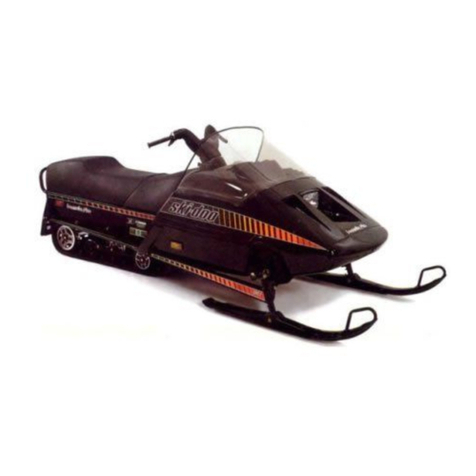
TABLE OF CONTENTS
CLEANING.......................................................................................................... 222
INSPECTION........................................................................................................ 223
ASSEMBLY ......................................................................................................... 223
INSTALLATION ..................................................................................................... 225
DRIVE PULLEY ADJUSTMENT ................................................................................... 226
03 – DRIVEN PULLEY ............................................................................................ 227
HPV VSA...................................................................................................... 227
REMOVAL .......................................................................................................... 228
DISASSEMBLY ..................................................................................................... 228
CLEANING.......................................................................................................... 228
INSPECTION........................................................................................................ 228
ASSEMBLY ......................................................................................................... 228
INSTALLATION ..................................................................................................... 229
ADJUSTMENT...................................................................................................... 230
04 – PULLEY DISTANCE AND ALIGNMENT.................................................................. 231
GENERAL........................................................................................................... 231
PROCEDURE ....................................................................................................... 231
PULLEY ALIGNMENT AND DISTANCE SPECIFICATIONS CHART. . . .. .. . . . .. . .. .. . . . .. .. . .. . . . .. .. . .. . . . .. .. . 232
05 – BRAKE ........................................................................................................ 233
HYDRAULIC BRAKE ........................................................................................ 233
GENERAL........................................................................................................... 234
BRAKE FLUID ...................................................................................................... 234
MASTER CYLINDER ............................................................................................... 234
CALIPER ............................................................................................................ 236
BRAKE PADS ....................................................................................................... 236
BRAKE DISC........................................................................................................ 237
BRAKE LIGHT SWITCH . .. .. . . . .. . . . . . . .. . . . .. . . .. . . . . . . .. . . . .. . . . .. .. .. . . . .. . . . . . . .. . . . .. . . .. . .. .. . . . .. . .. .. . . . .. . 239
BLEEDING .......................................................................................................... 240
06 – GEARBOX AND FINAL DRIVE BELT...................................................................... 241
GEARBOX .................................................................................................... 243
OIL CHANGE ....................................................................................................... 243
SHIFTER ADJUSTMENT........................................................................................... 243
REVERSE SWITCH ADJUSTMENT .. . . . .. . . . . . .. . . . .. . . . .. . . . . . . .. . . .. . . . .. . .. .. . . . .. . . . . . .. . . . .. . . . .. . . . . . . .. . . . 244
REMOVAL .......................................................................................................... 244
DISASSEMBLY ..................................................................................................... 244
INSPECTION........................................................................................................ 245
ASSEMBLY ......................................................................................................... 245
INSTALLATION ..................................................................................................... 245
FINAL DRIVE BELT.......................................................................................... 245
INSPECTION........................................................................................................ 245
DEFLECTION ADJUSTMENT ..................................................................................... 246
REMOVAL .......................................................................................................... 246
INSTALLATION ..................................................................................................... 247
07 ELECTRICAL SYSTEM
01 – ALTERNATOR................................................................................................ 249
REMOVAL .......................................................................................................... 250
INSPECTION........................................................................................................ 250
INSTALLATION ..................................................................................................... 250
BELT TENSION ADJUSTMENT ................................................................................... 250
02 – BATTERY ..................................................................................................... 251
GENERAL........................................................................................................... 251
V

TABLE OF CONTENTS
REMOVAL .......................................................................................................... 251
CLEANING.......................................................................................................... 251
INSPECTION........................................................................................................ 251
BATTERY CHARGE TESTING ..................................................................................... 251
BATTERY CHARGING.............................................................................................. 252
BATTERY STORAGE ............................................................................................... 252
ACTIVATION OF NEW BATTERY.................................................................................. 252
INSTALLATION OF BATTERY ..................................................................................... 252
CABLE TERMINAL INSTALLATION .. . .. .. . . . .. . . . .. . . . .. .. . .. . . . .. . . . . . .. . . . .. . . . .. . . . .. . . .. . .. .. . . . .. . . . . . . .. . . . 252
03 – ELECTRIC STARTER ........................................................................................ 255
REMOVAL .......................................................................................................... 256
DISASSEMBLY ..................................................................................................... 256
CLEANING.......................................................................................................... 257
PARTS INSPECTION . .. . .. . . . .. .. . .. . . . .. . . . . . .. . . . .. . . . .. .. . .. . . . .. . . . . . .. . . . .. . . . .. .. . .. . . . .. . . . . . .. . . . .. . . . .. .. . 258
ASSEMBLY ......................................................................................................... 258
INSTALLATION ..................................................................................................... 259
STARTER SPECIFICATION . . . . .. . . . .. . . . .. . . . . . .. . . . .. . . . .. . . . .. . . . .. .. . .. . . . .. . . . .. . . . .. .. .. . . . .. . . . . . . .. . . . .. . . . 260
04 – TESTING PROCEDURE..................................................................................... 261
INSPECTION OF HEATING ELEMENTS . . . .. . . .. . . . .. . .. .. . . . .. . . . . . .. . . . .. . . . .. . . . . . . .. . . .. . . . .. . . . . . . .. . . . .. . . . 261
HEADLIGHT AND ACCESSORIES SYSTEMS TESTING. . . .. . . . .. . . .. . . . .. . . . . . . .. . . . .. . . .. . .. .. . . . .. . . . . . . .. . . . 261
08 REAR SUSPENSION
01 – SC-10 III SUSPENSION..................................................................................... 263
GENERAL........................................................................................................... 267
COMPONENT REMOVAL AND INSTALLATION................................................................. 267
SUSPENSION ASSEMBLY REMOVAL. . .. . . . .. .. . .. . . . .. .. . .. . . . .. .. .. . . . .. . .. .. . . . .. . . . . . .. . . . .. . . . .. . .. .. . . . .. . 268
DISASSEMBLY AND ASSEMBLY . . .. . . . .. . . . .. . . . . . .. . . . .. . . . .. . .. .. . . . .. . . . . . .. . . . .. . . . .. .. . .. . . . .. .. . .. . . . .. . . . 269
SHOCK ABSORBER INSPECTION . .. . .. . . . .. .. . . . .. . . . .. . . . .. .. . .. . . .. . .. .. . . . .. . .. .. . . . .. .. . .. . . . .. .. . .. . . . .. .. . 272
INSTALLATION ..................................................................................................... 272
LUBRICATION...................................................................................................... 272
02 – DRIVE AXLE.................................................................................................. 273
REMOVAL .......................................................................................................... 274
ASSEMBLY ......................................................................................................... 274
INSTALLATION ..................................................................................................... 275
LUBRICATION...................................................................................................... 275
ADJUSTMENT...................................................................................................... 275
03 – TRACK ........................................................................................................ 277
TRACK TYPE APPLICATION. . . .. . . . . . . .. . . . .. . . .. . . . . . . .. . . . .. . . . .. . . .. . . . .. . .. .. . . . .. . . . . . .. . . . .. . . . .. . . . .. . . . .. . 277
GENERAL........................................................................................................... 277
INSPECTION........................................................................................................ 277
REMOVAL .......................................................................................................... 277
INSTALLATION ..................................................................................................... 277
ADJUSTMENT...................................................................................................... 277
09 STEERING/FRONT SUSPENSION
01 – STEERING SYSTEM ........................................................................................ 281
GENERAL........................................................................................................... 282
STEERING ADJUSTMENT (SKIS) ................................................................................. 282
GRIP................................................................................................................. 285
STEERING WHEEL................................................................................................. 285
LOWER STEERING COLUMN .................................................................................... 287
SHORT AND LONG TIE-RODS.................................................................................... 287
VI

TABLE OF CONTENTS
STEERING ARM.................................................................................................... 288
LUBRICATION...................................................................................................... 289
02 – FRONT SUSPENSION...................................................................................... 291
DISASSEMBLY ..................................................................................................... 292
INSPECTION........................................................................................................ 292
INSTALLATION ..................................................................................................... 292
10 BODY/FRAME
01 – BODY.......................................................................................................... 295
INSTALLATION AND ADJUSTMENT .................................................................... 295
HEADLAMP BEAM AIMING ...................................................................................... 295
BULB REPLACEMENT............................................................................................. 295
REARVIEW MIRROR............................................................................................... 296
DECAL .............................................................................................................. 296
WINDSHIELD INSTALLATION .................................................................................... 296
GUARD.............................................................................................................. 297
BODY................................................................................................................ 297
WIRING HARNESS................................................................................................. 299
CABLES............................................................................................................. 299
TUBING ............................................................................................................. 299
PLASTIC MAINTENANCE AND REPAIR ................................................................. 299
MAINTENANCE .................................................................................................... 299
WINDSHIELD REPAIR ............................................................................................. 300
BODY REPAIR...................................................................................................... 300
TOOLS AND MATERIALS LIST ................................................................................... 302
02 – FRAME........................................................................................................ 305
FRAME CLEANING ................................................................................................ 305
FRAME WELDING ................................................................................................. 305
FRAME COMPONENT REPLACEMENT ......................................................................... 305
11 TECHNICAL DATA
01 – SI METRIC INFORMATION GUIDE ....................................................................... 307
SI* METRIC INFORMATION GUIDE.............................................................................. 307
02 – ENGINE ....................................................................................................... 309
03 – VEHICLE ...................................................................................................... 315
04 – TECHNICAL DATA LEGENDS ............................................................................. 317
ENGINE LEGEND .................................................................................................. 317
VEHICLE LEGEND ................................................................................................. 317
12 WIRING DIAGRAM
01 – WIRING DIAGRAM.......................................................................................... 319
WIRING DIAGRAM LEGEND...................................................................................... 319
WIRE COLORS..................................................................................................... 319
CONNECTOR HOUSING AREA................................................................................... 319
HOUSING REFERENCE CODE PER AREA....................................................................... 320
WIRE LOCATION IN CONNECTOR HOUSING .................................................................. 320
SYMBOLS DESCRIPTION......................................................................................... 322
UNPLUGING CONNECTORS...................................................................................... 323
TAB AND RECEPTACLE CONNECTORS REMOVAL ............................................................ 323
TAB AND RECEPTACLE CONNECTORS INSTALLATION....................................................... 332
VII

SAFETY NOTICE
SAFETY NOTICE
This manual has been prepared as a guide to correctly service and repair some 2004 Ski-Doo®snowmo-
biles. See model list below.
This edition was primarily published to be used by snowmobile mechanic technicians who are already
familiar with all service procedures relating to Bombardier†made snowmobiles. Mechanic technicians
should attend continuous training courses given by Bombardier†Training Dept.
Please note that the instructions will apply only if proper hand tools and special service tools are used.
This Shop Manual uses technical terms which may be slightly different from the ones used in the Parts
Catalog.
It is understood that this manual may be translated into another language. In the event of any discrep-
ancy, the English version shall prevail.
The content depicts parts and/or procedures applicable to the particular product at time of writing. Ser-
vice and Warranty Bulletins may be published to update the content of this manual. Make sure to read
and understand them.
In addition, the sole purpose of the illustrations throughout the manual, is to assist identification of the
general configuration of the parts. They are not to be interpreted as technical drawings or exact replicas
of the parts.
The use of Bombardier parts is most strongly recommended when considering replacement of any com-
ponent. Dealer and/or distributor assistance should be sought in case of doubt.
The engines and the corresponding components identified in this document should not be utilized on
product(s) other than those mentioned in this document.
This manual emphasizes particular information denoted by the wording and symbols:
WARNING
Identifies an instruction which, if not followed, could cause serious personal injury including pos-
sibility of death.
CAUTION: Denotes an instruction which, if not followed, could severely damage vehicle compo-
nents.
NOTE: Indicates supplementary information needed to fully complete an instruction.
Although the mere reading of such information does not eliminate the hazard, your understanding of the
information will promote its correct use. Always use common shop safety practice.
Bombardier Recreational Products Inc. (BRP) disclaims liability for all damages and/or injuries resulting
from the improper use of the contents. We strongly recommend that any services be carried out and/or
verified by a highly skilled professional mechanic. It is understood that certain modifications may render
use of the vehicle illegal under existing federal, provincial and state regulations.
WARNING
Torque wrench tightening specifications must strictly be adhered to. Locking devices (ex.: lock-
ing tab, self-locking fasteners, etc.) must be installed or replaced with new ones. If the efficiency
of a locking device is impaired, it must be renewed.
WARNING
Unless otherwise specified, engine should be turned OFF and cold for all maintenance and repair
procedures.
VIII

INTRODUCTION
INTRODUCTION
This shop manual covers the following BRP made
2004 Elite series models:
A34A01E
TYPICAL — ELITE SERIES
MODEL ENGINE COLOR MODEL
NUMBER
Elite SE
CAN/U.S. 1500 Silver 2227
Elite SE
Europe 1500 Silver 4070
VEHICLE IDENTIFICATION
NUMBER
VEHICLE IDENTIFICATION
NUMBER LOCATION
A34H02A
1
TYPICAL
1. Vehicle identification number
IDENTIFICATION NUMBER
MEANING
2 B P S 1 5 9 2 9 Y 1 0 0 0 0 0 1
A00A6EA
Model number Serial number
Model year: y = 2000
1 = 2001
2 = 2002
e c.
IX

INTRODUCTION
ENGINE SERIAL NUMBER
LOCATION
A34C0EC
1
TYPICAL
1. Engine serial number
LIST OF ABBREVIATIONS USED IN
THIS MANUAL
ABBREVIATION MEANING
Aampere
amp ampere
A•hampere-hour
AC alternate current
ACM acceleration and control
modulator
ADSA advanced direct shock action
AMG absorbed glass mat
APS air pressure sensor
ATS air temperature sensor
BDC bottom dead center
BTDC before top dead center
B.U.D.S. Bombardier Utility and
Diagnostic Software
°Cdegree Celsius
cc cubic centimeter
ABBREVIATION MEANING
CDI capacitor discharge ignition
CPS Crankshaft Position Sensor
CTR center
cm centimeter
cm²square centimeter
cm³cubic centimeter
DC direct current
DESS digitally encoded security
system
DPM digital performance
management
°Fdegree Fahrenheit
FC fan cooled
fl. oz fluid ounce
ft foot
GRD ground
H.A.C. high altitude compensator
hal. halogen
HI high
IFP internal floating piston
imp. oz imperial ounce
in inch
in²square inch
in³cubic inch
kkilo (thousand)
kg kilogram
km/h kilometer per hour
kPa Kilopascal
Lliter
lb pound
lbf pound (force)
lbf/in²pound per square inch
LH left hand
X

INTRODUCTION
ABBREVIATION MEANING
LO low
mmeter
MAG magneto
Max. maximum
Min. minimum
mL milliliter
mm millimeter
MPEM multi-purpose electronic
module
MPH mile per hour
Nnewton
N.A. not applicable
no. number
0continuity
0.L open line (open circuit)
O.D. outside diameter
OPT optional
oz ounce
P/N part number
PSI pound per square inch
PTO power take off
Rrectangular
RH right hand
RAVE Rotax adjustable variable
exhaust
RER Rotax electronic reverse
RPM revolution per minute
RMS root mean square
RRIM reinforced reaction injection
molding
Sp. Gr. specific gravity
ST semi-trapez
TDC top dead center
TPS throttle position sensor
ABBREVIATION MEANING
TRA total range adjustable
U.S. oz ounce (United States)
Vvolt
Vac volt (alternative current)
Vdc Volt (direct current)
VSA variable sheave angle
WTS water temperature sensor
ARRANGEMENT OF THIS
MANUAL
The manual is divide into 12 major sections:
01 Service Tools and Service Products
02 Maintenance
03 Troubleshooting
04 1503 Engine (4-TEC)
05 1503 Engine Management (4-TEC)
06 Transmission
07 Electrical System
08 Rear Suspension
09 Steering/Front Suspension
10 Body/Frame
11 Technical Data
12 Wiring Diagram
Each section is divided in various subsections, and
again, each subsection has one or more division.
XI

INTRODUCTION
GENERAL INFORMATION
The information and component/system descrip-
tions contained in this manual are correct at time
of publication. BRP however, maintains a policy
of continuous improvement of its products with-
out imposing upon itself any obligation to install
them on products previously manufactured.
Due to late changes, it may have some differences
between the manufactured product and the de-
scription and/or specifications in this document.
BRP reserves the right at any time to discontinue
or change specifications, designs, features, mod-
els or equipment without incurring obligation.
ILLUSTRATIONS AND
PROCEDURES
Illustrations and photos show the typical construc-
tion of the different assemblies and, in all cases,
may not reproduce the full detail or exact shape of
the parts shown. However, they represent parts
which have the same or a similar function.
CAUTION: Most components of those vehicles
are built with parts dimensioned in the metric
system. Most fasteners are metric and must
not be replaced by customary fasteners or
vice-versa. Mismatched or incorrect fasteners
could cause damage to the vehicle or possible
personal injury.
As many of the procedures in this manual are inter-
related, we suggest, that before undertaking any
task, you read and thoroughly understand the en-
tire section or subsection in which the procedure
is contained.
A number of procedures throughout the book re-
quire the use of special tools. Before commenc-
ing any procedure, be sure that you have on hand
all the tools required, or approved equivalents.
The use of RIGHT and LEFT indications in the text,
always refers to driving position (when sitting on
vehicle).
SELF-LOCKING APPLICATION
PROCEDURE
The following describes the most common appli-
cation procedures when working with self-locking
fasteners.
Use a metal brush or a tap to clean the hole prop-
erly then use a solvent (Methyl-Chloride), let act
during 30 minutes and wipe off. The solvent uti-
lization is to ensure the adhesive works properly.
LOCTITE®APPLICATION
PROCEDURE
The following describes the most common ap-
plication procedures when working with Loctite
products.
NOTE: Always use proper strength Loctite prod-
uct as recommended in this Shop Manual.
THREADLOCKER
Uncovered Holes (bolts and nuts)
A00A3LA
1
2
1. Apply here
2. Do not apply
–Clean threads (bolt and nut) with solvent.
–Apply Loctite Primer N (P/N 293 800 041) on
threads and allow to dry.
–Choose proper strength Loctite threadlocker.
–Fit bolt in the hole.
–Apply a few drops of threadlocker at proposed
tightened nut engagement area.
–Position nut and tighten as required.
XII

INTRODUCTION
Blind Holes
A00A3MA
1
2
1. On threads
2. On threads and at the bottom of hole
–Clean threads (bolt and hole) with solvent.
–Apply Loctite Primer N (P/N 293 800 041) on
threads (bolt and nut) and allow to dry for 30
seconds.
–Choose proper strength Loctite threadlocker.
–Apply several drops along the threaded hole and
at the bottom of the hole.
–Apply several drops on bolt threads.
–Tighten as required.
Stud in Blind Holes
A00A3NA
2
13
1. On threads
2. On threads and in the hole
3. Onto nut threads
–Clean threads (stud and hole) with solvent.
–Apply Loctite Primer N (P/N 293 800 041) on
threads and allow to dry.
–Put several drops of proper strength Loctite
threadlocker on female threads and in hole.
–Apply several drops of proper strength Loctite
on stud threads.
–Install stud.
–Install cover, etc.
–Apply drops of proper strength Loctite on un-
covered threads.
–Tighten nuts as required.
Preassembled Parts
A00A3OA
1
2
1. Apply here
2. Do not apply
–Cleanboltsandnutswithsolvent.
–Assemble components.
–Tighten nuts.
–Apply drops of proper strength Loctite on
bolt/nut contact surfaces.
–Avoid touching metal with tip of flask.
NOTE: For preventive maintenance on exist-
ing equipment, retighten nuts and apply proper
strength Loctite on bolt/nut contact surfaces.
XIII

INTRODUCTION
Adjusting Screw
A00A3PA
1
2
1. Apply here
2. Plunger
–Adjust screw to proper setting.
–Apply drops of proper strength Loctite thread-
locker on screw/body contact surfaces.
–Avoid touching metal with tip of flask.
NOTE: If it is difficult to readjust, heat screw with
a soldering iron (232 °C(450°F)).
STRIPPED THREAD REPAIR
Stripped Threads
A00A3QA
5
8
6
7
1
2
3
4
1. Release agent
2. Stripped threads
3. Form-A-Thread
4. Tape
5. Cleaned bolt
6. Plate
7. New threads
8. Threadlocker
Standard Thread Repair
–Follow instructions on Loctite FORM-A-
THREAD 81668 package.
–If a plate is used to align bolt:
–Apply release agent on mating surfaces.
–Put waxed paper or similar film on the sur-
faces.
–Twist bolt when inserting it to improve thread
conformation.
NOTE: NOT intended for engine stud repairs.
Repair of Small Holes/Fine Threads
Option 1: Enlarge damaged hole, then follow
STANDARD THREAD REPAIR procedure.
Option 2: Apply FORM-A-THREAD on the screw
and insert in damaged hole.
Permanent Stud Installation (light duty)
–Use a stud or thread on desired length.
–DO NOT apply release agent on stud.
–Do a STANDARD THREAD REPAIR.
–Allow to cure for 30 minutes.
–Assemble.
GASKET COMPOUND
All Parts
A00A3SA
2
1
13
1
1. Proper strength Loctite
2. Loctite Primer N (P/N 293 800 041) and Gasket Eliminator
515 (P/N 413 702 700) on both sides of gasket
3. Loctite Primer N only
–Remove old gasket and other contaminants
with Loctite Chisel remover (P/N 413 708 500).
Use a mechanical mean if necessary.
XIV

INTRODUCTION
NOTE: Avoid grinding.
–Clean both mating surfaces with solvent.
–Spray Loctite Primer N on both mating surfaces
andonbothsidesofgasket. Allowtodry1or
2 minutes.
–Apply gasket eliminator 515 (P/N 413 702 700)
on both sides of gasket, using a clean applicator.
–Place gasket on mating surfaces and assemble
immediately.
NOTE: If the cover is bolted to blind holes (above),
apply proper strength Loctite in the hole and on
threads. Tighten.
If holes are sunken, apply proper strength Loctite
on bolt threads.
–Tighten as usual.
MOUNTINGONSHAFT
Mounting with a Press
A00A3UA
1
2
3
1. Bearing
2. Proper strength Loctite
3. Shaft
Standard
–Clean shaft external part and element internal
part.
–Apply a strip of proper strength Loctite on shaft
circumference at insert or engagement point.
NOTE: Retaining compound is always forced out
whenappliedonshaft.
–DO NOT use anti-seize Loctite or any similar
product.
–No curing period is required.
Mounting in Tandem
–Apply retaining compound on internal element
bore.
–Continue to assemble as shown above.
CASE-IN COMPONENTS
Metallic Gaskets
A00A3VA 1
1. Proper strength Loctite
–Clean inner housing diameter and outer gasket
diameter.
–Spray housing and gasket with Loctite Primer N
(P/N 293 800 041).
–Apply a strip of proper strength Loctite on lead-
ing edge of outer metallic gasket diameter.
NOTE: Any Loctite product can be used here. A
low strength liquid is recommended as normal
strength and gap are required.
–Install according to standard procedure.
–Wipe off surplus.
–Allow it to cure for 30 minutes.
NOTE: Normally used on worn-out housings to
prevent leaking or sliding.
It is generally not necessary to remove gasket
compound applied on outer gasket diameter.
XV

INTRODUCTION
TIGHTENING TORQUE
Tighten fasteners to torque mentioned in exploded views and/or text, When they are not specified, refer
to following table. The table also gives the metric conversion.
WARNING
Torque wrench tightening specifications must strictly be adhered to. Locking devices (ex.: lock-
ing tabs, elastic stop nuts, self-locking fasteners, etc.) must be installed or replaced with new
ones, where specified. If the efficiency of a locking device is impaired, it must be renewed.
In order to avoid a poor assembling, tighten screws, bolts or nuts in accordance with the following pro-
cedure:
–Manually screw all screws, bolts and/or nuts.
–Apply the half of the recommended torque value.
CAUTION: Be sure to use proper tightening torque for the proper strength grade.
A00A8BS
Proper y
class
and
head
markings
Proper y
class
and
nu
markings
5
5
10
10
10
10
12
12
4.8
4.8
4.8
8.8
8.8
8.8
9.8
9.8
9.8
10.9
10.9
10.9
12.9
12.9
12.9
12.9
FASTENER GRADE/TORQUE
FASTENER
SIZE 5.8 Grade 8.8 Grade 10.9 Grade 12.9 Grade
M4 1.5 —2N•m
(13 —18 lbf•in)
2.5 —3N•m
(22 —27 lbf•in)
3.5 —4N•m
(31 —35 lbf•in)
4—5N•m
(35 —44 lbf•in)
M5 3—3.5 N•m
(27 —31 lbf•in)
4.5 —5.5 N•m
(40 —47 lbf•in)
7—8.5 N•m
(62 —75 lbf•in)
8—10 N•m
(71 —89 lbf•in)
M6 6.5 —8.5 N•m
(58 —75 lbf•in)
8—12 N•m
(71 —106 lbf•in)
10.5 —15 N•m
(93 —133 lbf•in)16 N•m (142 lbf•in)
M8 15 N•m(11lbf•ft) 24.5 N•m(18lbf•ft) 31.5 N•m(23lbf•ft) 40 N•m(30lbf•ft)
M10 29 N•m(21lbf•ft) 48 N•m(35lbf•ft) 61 N•m(45lbf•ft) 72.5 N•m(53lbf•ft)
M12 52 N•m(38lbf•ft) 85 N•m(63lbf•ft) 105 N•m(77lbf•ft) 127.5 N•m(94lbf•ft)
M14 85 N•m(63lbf•ft) 135 N•m(100lbf•ft) 170 N•m (125 lbf•ft) 200 N•m (148 lbf•ft)
XVI

INTRODUCTION
We would be pleased if you could
communica e o BRP any sugges ions
you may have concerning our publi-
ca ions.
!
A00A89
BRP SERVICE PUBLICATIONS REPORT
Publica ion i le and year Page
Machine Repor of error q Sugges ion q
Name
Address
Ci y and S a e/Prov. Da e
Zip code/Pos al code
BRP SERVICE PUBLICATIONS REPORT
Publica ion i le and year Page
Machine Repor of error q Sugges ion q
Name
Address
Ci y and S a e/Prov. Da e
Zip code/Pos al code
BRP SERVICE PUBLICATIONS REPORT
Publica ion i le and year Page
Machine Repor of error q Sugges ion q
Name
Address
Ci y and S a e/Prov. Da e
Zip code/Pos al code
XVII
Table of contents
Other Ski-Doo Offroad Vehicle manuals

Ski-Doo
Ski-Doo MX Z X 440 Manual

Ski-Doo
Ski-Doo CK3 Series Manual

Ski-Doo
Ski-Doo Legend Manual

Ski-Doo
Ski-Doo Tundra Series Manual

Ski-Doo
Ski-Doo CK 3 Manual

Ski-Doo
Ski-Doo Skandic Series Manual

Ski-Doo
Ski-Doo Escapade 1987 User manual

Ski-Doo
Ski-Doo Mini Z Manual

Ski-Doo
Ski-Doo CK3 Series Manual

Ski-Doo
Ski-Doo Mini Z Manual

Ski-Doo
Ski-Doo Scandic WT 550F Manual

Ski-Doo
Ski-Doo 1990 Elan User manual

Ski-Doo
Ski-Doo 1980 Everest 500 User manual

Ski-Doo
Ski-Doo Tundra Series Manual

Ski-Doo
Ski-Doo 2005 SUMMIT HIGHMARK X Install guide

Ski-Doo
Ski-Doo SCANDIC WT Manual

Ski-Doo
Ski-Doo Tundra Series Manual

Ski-Doo
Ski-Doo 2006 MX Z Manual

Ski-Doo
Ski-Doo Safari Scout User manual

Ski-Doo
Ski-Doo MX Z Iron Dog Manual