SKI AccuFlo Zero User manual
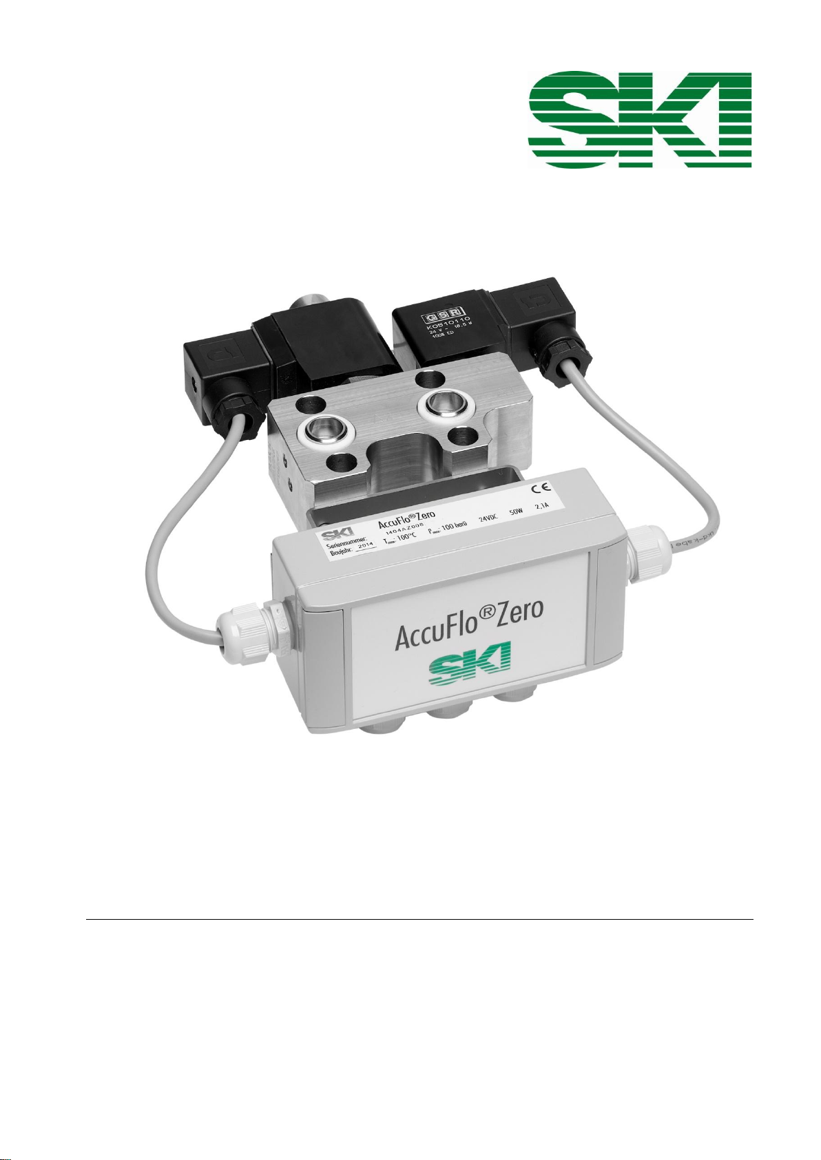
AccuFlo®Zero
Automatic Zero-Point Calibration
For Differential Pressure Transmitters
Installation and Operating Instructions

AccuFlo®Zero –Installation and Operating Instructions
2
Installation and operating instructions AccuFlo®Zero
Attention:
Please refer to the warning information on page 3 and 4 before commissioning!
Content
1General information ......................................................................................................3
1.1 Safety information...............................................................................................................................3
1.2 Qualified personnel.............................................................................................................................3
1.3 Further information .............................................................................................................................3
1.4 Special warnings.................................................................................................................................4
2Correct usage ................................................................................................................5
3Description of functions ...............................................................................................5
4Inspection of incoming goods......................................................................................6
5Electrical connections and assembling ......................................................................7
5.1 Installation of the AccuFlo®Zero .........................................................................................................7
5.2 Electrical connections.........................................................................................................................8
5.3 Status relay.........................................................................................................................................9
5.4 Manual zero-point calibration..............................................................................................................9
5.5 Terminal assignment ..........................................................................................................................9
6Commissioning............................................................................................................13
6.1 General procedure............................................................................................................................13
6.2 Successful set up..............................................................................................................................13
6.3 Optional correction of positioning with steam measurements and condensate in the system.........13
6.4 Delete a correction of positioning .....................................................................................................14
6.5 Signaling to the control station..........................................................................................................14
7Operation .....................................................................................................................14
8Errors............................................................................................................................14
8.1 Signaling of errors.............................................................................................................................14
8.2 LED lights up permanently................................................................................................................15
8.3LED does not light up .......................................................................................................................15
8.4 LED is flashing permanently.............................................................................................................15
9Technical data..............................................................................................................16
9.1 General information ..........................................................................................................................16
9.2 Electrical data ...................................................................................................................................17
10 Declaration of Confirmity............................................................................................18
S.K.I. Schlegel & Kremer Industrieautomation GmbH
Hanns-Martin-Schleyer-Str. 22 –41199 Mönchengladbach
Tel: +49 (0) 2166/62317-0

AccuFlo®Zero –Installation and Operating Instructions
3
Installation and operating instructions AccuFlo®Zero
1 General information
1.1 Safety information
This device left the factory free from safety problems. In order to maintain this status and to ensure safe
operation of the device, please observe the safety information and warnings contained in this instruction.
The device/system may only be set up and used in conjunction with this documentation.
Correct, reliable operation of the product requires proper transport, storage, positioning and assembly
as well as careful operation and maintenance by qualified personnel.
This device may only be used for the applications described in the technical description and only in
connection with devices or components from other manufacturers which have been approved or
recommended by S.K.I. GmbH.
You are obliged to respect the test certificates, provisions and laws applicable in your country during
connection, assembly and operation of the device/system.
The device can be operated both at high pressure and with aggressive and hazardous media.
Therefore, improper use of this device may lead to serious injury and/or considerable damage to
property. Especially, it must be noted when the device was in use and is to be exchanged.
Commissioning and operation of a device/system may only be performed by qualified personnel. This
personnel has to see to it that appropriate voltage is used (see type stamp), that ensures that in normal
operation or in case of default of the device or of components no hazardous voltages may damage the
device. Insofar, improper use of this device may lead to serious injury and / or considerable damage to
property.
1.2 Qualified personnel
The installation and operating must be realized by qualified personnel. Qualified personnel includes persons
familiar with the installation, assembly, commissioning and operation of the product and who have the
appropriate qualifications for their activities such as
They are authorized, trained or instructed in operating and maintaining devices and systems according
to the safety regulations for electrical circuits, for media under high pressure or aggressive or hazardous
media.
For explosion-proof devices: They are authorized, trained, or instructed in carrying out work on electrical
circuits for hazardous systems.
They are authorized, trained or instructed in safety standards for maintenance and use of appropriate
safety equipment.
Training in first aid.
1.3 Further information
For clarity reasons, this notice does not contain all detailed information of all types of products and may not
consider every possible application or maintenance.
Attention: If you need more information or have particular problems which are not covered sufficiently by the
operating instructions, get in touch with S.K.I. GmbH directly (see last page). You may find contact information
in the internet.
The contents of these instructions shall not become part of or modify any prior or existing agreement,
commitment or legal relationship. All obligations on behalf of S.K.I. GmbH are contained in the respective sales
contract which also contains the complete and solely applicable warranty conditions. Any statements contained
herein do not create new warranties or modify the existing warranty.
The content reflects the technical status at the time of printing. We reserve the right to make technical changes
in the course of further development.

AccuFlo®Zero –Installation and Operating Instructions
4
Installation and operating instructions AccuFlo®Zero
1.4 Special warnings
Exceeding pressure: Appropriate measures are to be taken to secure that the allowed operation pressure
according to the stamp on the type plate is not exceeded.
Normal usage: On acceptance and within the required control intervals, a compression test under overpressure
and a leakage test have to be conducted for the whole system.
Exceeding or underrunning of the allowed operation temperature limits: Appropriate measures are to be
taken to secure that the allowed operation temperature limits are not exceeded.
Damage: Please observe that the product is not dropped and that it is not affected by excess forces.
Too many load cycles: Appropriate measures are to be taken to secure that the allowed number of load cycles
is not exceeded. The maximum load cycles are defined in EN 13480-3; 10.2 c).
Opening under pressure: Appropriate measures are to be taken to secure that the valves of the product are
not opened under pressure.
Fire near the product: Appropriate measures are to be taken to secure that the product is taken out of
operation in case of damage.
Improper mounting of the flow computer: Please observe that the several components of the product are
mounted properly.
Improper mounting of the device: Please observe that the device is mounted properly.
Assembling of pieces of equipment, valves etc.: In case of assembling of pieces of equipment and when
starting the working load, the pressure devices shall not be exposed to any loads which may endanger the
operating safety. Especially, additional static and dynamic loads are not allowed.
Welding of pieces of equipment: Please observe that no welding, heat treatment or other interventions
concerning the safety are carried out. Necessary reparations have to be approved by the manufacturer.
Corrosion: Please observe that the product is used and installed as intended.
Electricity: Caution of voltage! Switch off the device before interfering in the wiring.
Other risks: Please observe that the operation instructions of the manufacturer are respected at all times.
Especially, pressure devices have to be used for the specified media.

AccuFlo®Zero –Installation and Operating Instructions
5
Installation and operating instructions AccuFlo®Zero
2 Correct usage
The AccuFlo®Zero is used for automatic zero-point calibrations. The device may only be used for the purposes
specified in these instructions. All changes to the device are the sole responsibility of the user if they are not
explicitly stated in these instructions,.
3 Description of functions
The AccuFlo®Zero continuously monitors the temperature of the measuring cell of the differential pressure
transmitter. The device performs a zero-point calibration in case the temperature change exceeds a pre-defined
threshold value. If no inacceptable temperature change occurs during an individually determined interval the
AccuFloZero® will perform a zero-point calibration to avoid long term drift of the differential pressure
transmitter’s zero point.
During any zero-point calibration the latest output signal will be upheld as a fixed value. Therefore, the
AccuFlo®Zero ensures that a continuous output signal is maintained even during zero-point calibration in order
not to disrupt subsequent control systems.
Communication between AccuFlo®Zero and differential pressure transmitter takes place via HART®-interface.
Thus the function of the AccuFlo®Zero is usually independent of the transmitter brand and model if the
transmitter supports the necessary functions via HART®. The automatic zero point calibration is executed
directly in the transmitter analog to a manual calibration with a possible present local computer or the use of a
HART®-terminal. Please contact us for a list of supported differential pressure transmitter models.
Properties
Integration in the system: Easy installation directly at the differential pressure transmitter.
Conservations of results: During the zero-point calibration the latest output signal generated by the
transmitter will be upheld as a constant output signal.
Duration of calibration: Approximately 30 sec.
Calibration by time interval: The zero-point calibration will be executed after an individually adjustable interval.
This standard interval is 24h.
Calibration by drift: The temperature of the cell in the transmitter is monitored and compared with a
value of the latest balance. Should this difference exceed an adjustable value, the
zero point balance will be executed. The standard value is 10 K.
Correction of the position: In case of deviations due to an improper assembling of the transmitter for steam
measurements a static offset may be fixed in the AccuFlo®Zero.
Communication
Analog output: The analog output of the transmitter is passed-through.
SPS or control terminal: Two relays transmit the status of the AccuFlo®Zero. These relays may be
combined to a sum alarm (see chapter 5.5, table 3 and following)
At any time, the zero-point calibration may be executed manually by a signal (see
chapter 5.4).

AccuFlo®Zero –Installation and Operating Instructions
6
Installation and operating instructions AccuFlo®Zero
4 Inspection of incoming goods
Please check the scope of supply for the following items:
AccuFlo®Zero
AccuFlo®Zero
1. AccuFlo®Zero
2. Threaded rods and screw nuts:
7/16-UNF or M10 (according to the
transmitter) for assembling of the
system.
3. PTFE-seals for the connection between
the AccuFlo®Zero and the transmitter.
4. (Optional) Two locking screws with
bleeder valve function for steam or
liquid applications.
5. Documentation
AccuFlo®Zero –Installation and Operating Instructions
7
Installation and operating instructions AccuFlo®Zero
5 Electrical connections and assembling
5.1 Installation of the AccuFlo®Zero
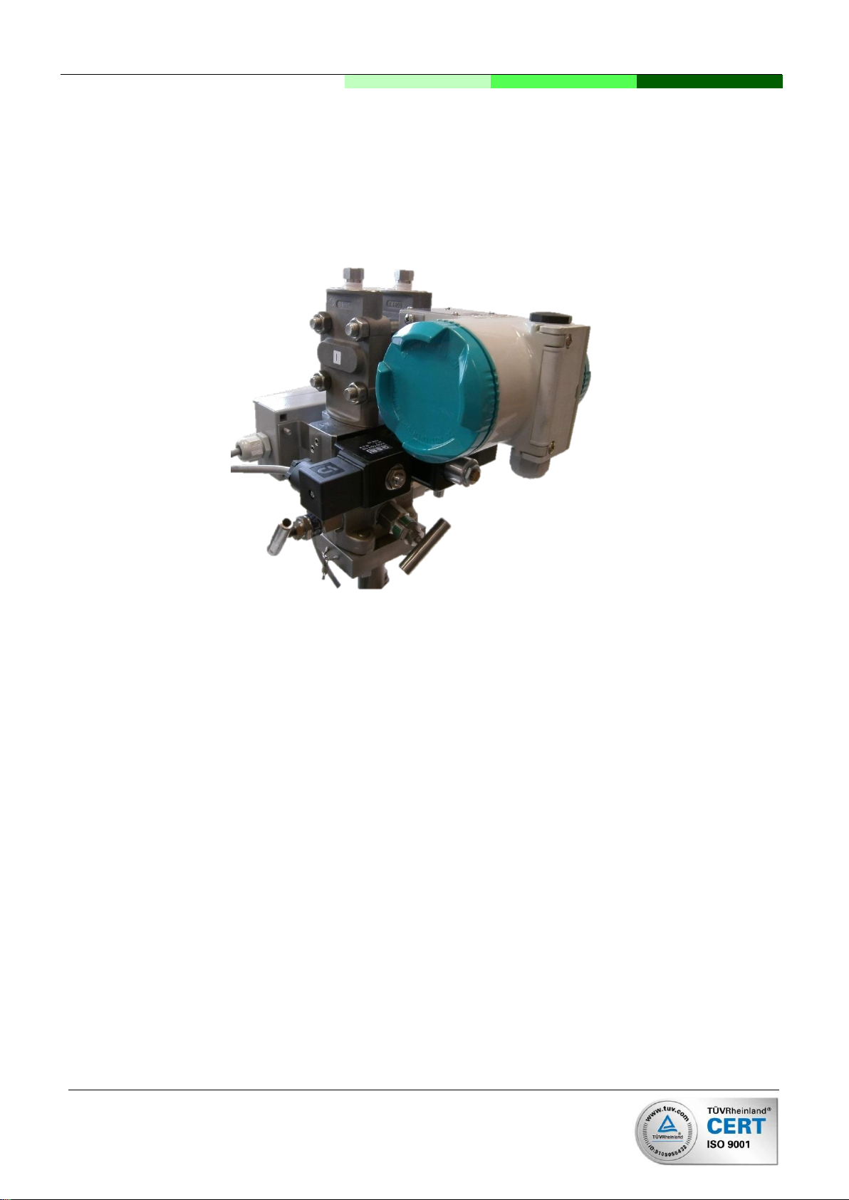
The AccuFlo®Zero has to be installed between the valve manifold and the differential pressure transmitter (see
Figure 1).
Figure 1: Assembled AccuFlo®Zero
The following has to be considered when installing the AccuFlo®Zero:
The use of the enclosed PTFE-seals prevent leakage when assembling the transmitter on the
AccuFlo®Zero and to the valve manifold.
The use of the right threaded rods (M10 or 7/16-UNF) guarantees the proper position of the devices.
This depends on the chosen transmitter.
The screws fix the AccuFlo®Zero and the transmitter to the manifold.
In case of measurement of liquids or steam the two locking screws without valve (see above in Figure 1:
Assembled AccuFlo®Zero) are to be replaced by the delivered locking screws with valve (bleeder valve).
After assembling and after maintenance these valves ensure that the impulse pressure pipes to the
transmitter are completely vented. After venting the impulse pipes the valves have to be tightened
thoroughly.
Instruction of procedure
Dismount the existing connection between the transmitter and the valve manifold. The existing screws
or threaded rods have to be removed from the transmitter. (This is only necessary if the transmitter and
the valve manifold are already connected).
Afterwards, the proper threaded rods have to be screwed into the transmitter.
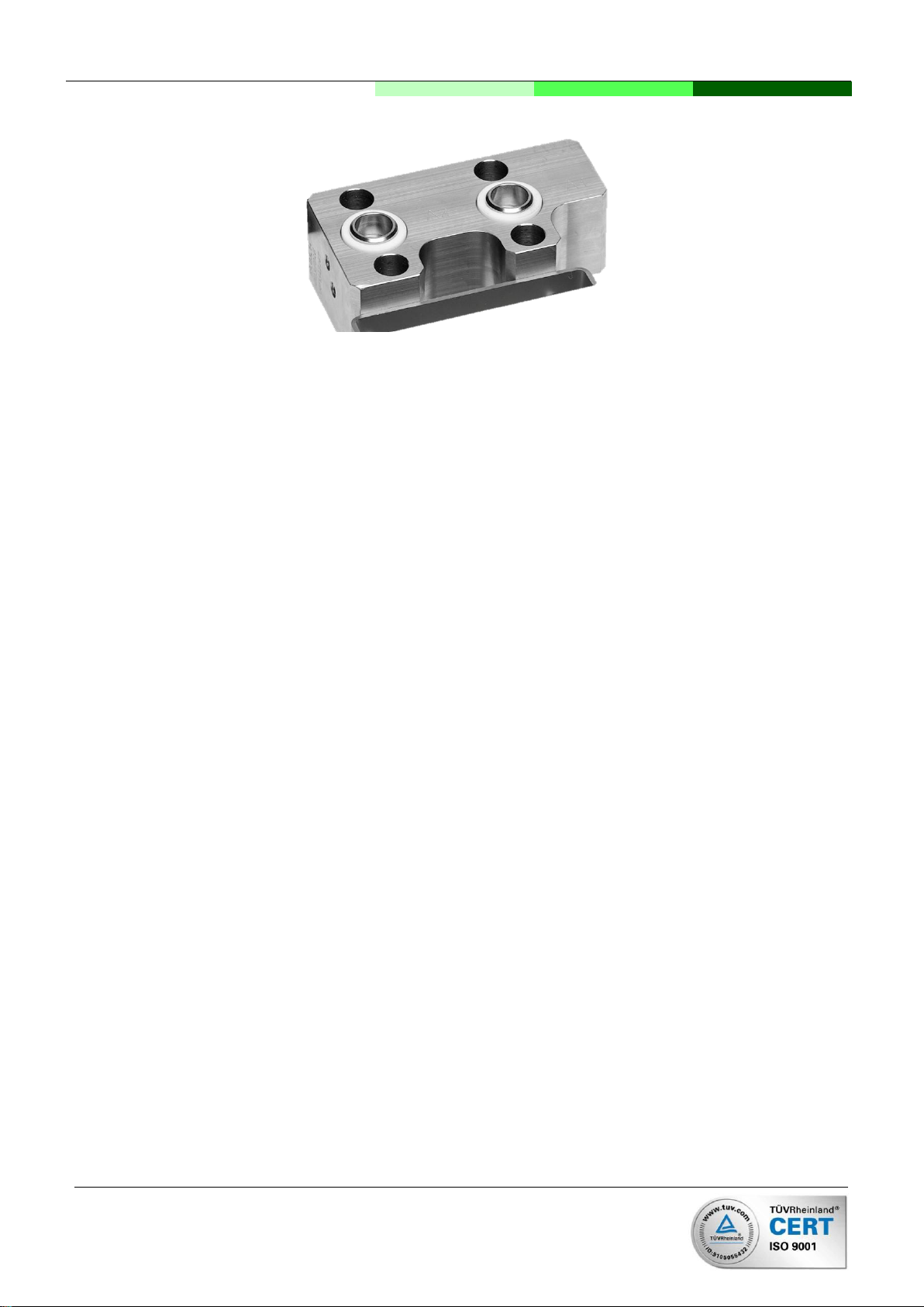
The seals have to be laid in the grooves of the AccuFlo®Zero (see figure Figure 2). The side with the
seals points to the transmitter. The junction box can be placed at the front or the back.
AccuFlo®Zero –Installation and Operating Instructions
8
Installation and operating instructions AccuFlo®Zero
Figure 2: Metal block of the AccuFlo®Zero
Then the AccuFlo®Zero is pushed upon the threaded rods.
Now the seals are laid in the grooves of the valve manifold (or existing ones are replaced). The valve
manifold is pushed upon the thread rods as well.
Last, the nuts are screwed loosely on the thread rods. After checking the right positions of all
components tighten the screws.
Attention: The assembling has to be checked thoroughly before commissioning!
5.2 Electrical connections
In the following chapter all electrical connections are described:
Power supply:
oThe AccuFlo®Zero needs a voltage supply of 24 V DC with a power rating of at least 2.1 ampere.
oWe recommend a switch-mode power supply.
oWe recommend positioning the power supply nearby the AccuFlo®Zero.
Wires from the AccuFlo®Zero to the transmitter:
oOne cable with 2 wires (two-wire interface 4–20 mA).
Wires from the AccuFlo®Zero to the control station:
oOne cable with 2 wires (two-wire interface 4–20 mA).
oOptional: one cable with 2 ore 3 wires for the status relay (or accordingly more wires for the
interface mentioned above).
oOptional: One cable with 2 wires for the manual triggering of the zero-point calibration (or
accordingly more leads for the interface mentioned above).
Attention: The AccuFlo®Zero does not dispose of a galvanic separation between the GND of the power supply
and the GND of the control station.

AccuFlo®Zero –Installation and Operating Instructions
9
Installation and operating instructions AccuFlo®Zero
5.3 Status relay
The AccuFlo®Zero includes two status relays which may offer following signals:
The relay “in operation” issues signal “1” if the AccuFlo®Zero is switched on and the transmitter is identified. In
case of error it issues a signal “0”. Possible errors: powerless AccuFlo®Zero, no transmitter identified, default on
the AccuFlo®Zero.
The relay “balanced” provides a 1-signal if the zero-point calibration is effected and real time results are
provided in the current loop. In any other case it provides a 0-signal: before the first zero-point calibration,
during the calibration if the calibration did not succeed. (Last results of the current loop is fixed and shown
statically during this period).
Both relays may be connected in series in the AccuFlo®Zero and provide a group signal. A 1-signal is only sent
if the AccuFlo®Zero is switched on, the transmitter is identified and the last zero-point calibration succeeded
(that means no zero-point calibration is needed). In all other cases (as well during the 30-seconds calibration) a
0-signal is provided.
There are two choices: either the AccuFlo®Zero sends a +24-V-signal to the control station or the relays switch
a signal sent by the control station.
5.4 Manual zero-point calibration
A zero-point calibration may be triggered by the control station or an external operator station. Then, the
terminal connection “G3” has to be connected with GND.
5.5 Terminal assignment
Overview of all terminal blocks on the AccuFlo®Zero:
Figure 3: Open AccuFlo®Zero
E1
E2
E3
E4
F1
F2
F3
F4
G1
G2
G3
G4
A1
A2
A3
A4
B1
B2
B3
B4
C1
C2
C3
C4
D1
D2
D3
D4
J1
J2
AccuFlo®Zero –Installation and Operating Instructions
10
Installation and operating instructions AccuFlo®Zero
Power supply of the AccuFlo®Zero:
Table 1: Jumper "J1" set/closed
Terminal
Description
Use
G4
+24 V
Power supply
E1
GND
24 V DC / 2 A
Connection between the AccuFlo®Zero and the differential pressure transmitter:
Table 2: Connection to the transmitter
Terminal
Terminal
in transmitter
Use
A4
+
Differential pressure transmitter 4–20 mA
D2
−
Connection between the AccuFlo®Zero and the control station:
Table 3: Analog signal to the control station
Terminal
Description
Use
A1
+
Analog output signal
A2
−
4–20 mA
If necessary:
Option 1: +24-V-signal from AccuFlo®Zero to the control
station mode „error“ and „OK“
Jumper „J1“ set/closed!
Table 4: Relay outputs –option 1:
Terminal
Description
Use
E3
+ (Calibrated)
Signal „Calibration Successful“
+24 V after successful zero-point calibration
E4
+ (Ready)
Signal „Ready“
+24 V if AccuFlo®Zero is ready

AccuFlo®Zero –Installation and Operating Instructions
11
Installation and operating instructions AccuFlo®Zero
Option 2: +24-V-signal from AccuFlo®Zero to the control
station mode as group message
Remove/open jumper „J2“. Connect terminal “E4” with “F4”!
Table 5: Relay output - option 2:
Terminal
Description
Use
E3
+
Signal „Ready and Calibration Successful”
+24 V if AccuFlo®Zero is ready and zero-
point calibration is successful
Option 3: Externally supplied signal from AccuFlo®Zero to
control station for status „Error“and „Ready“
Remove/open jumper „J2“.
Table 6: Relay outputs –option 3:
Terminal
Description
Use
E2
external + *
Externally supplied signal
E3
+ (Calibration)
Signal „Calibration“
+ of the manually supplied signal after
successful zero-point calibration
E4
+ (Calibration)
Signal „Ready“
+ of the manually supplied signal if the
AccuFlo®Zero is ready
Option 4: Externally supplied signal from AccuFlo®Zero to
control station as “group message“
Remove/open jumper „J2“.
Table 7: Relay outputs –option 4:
Terminal
Description
Use
E4
external + *
Externally supplied signal
E3
+ (Ready and
calibration
successful)
Signal „ Ready and calibration successful “
+ of the manually supplied signal, if the
AccuFlo®Zero is ready and the zero-point
calibration is successful
*Since mechanical relays may be used, also for example
alternating voltage may be chosen.

AccuFlo®Zero –Installation and Operating Instructions
12
Installation and operating instructions AccuFlo®Zero
If necessary: external triggering of the zero-point
calibration
Table 8: Signal „start zero-point calibration“ from the control
station to the AccuFlo®Zero
Terminal
Description
Use
D4
GND
GND of the AccuFlo®Zero
G3
GND = Start
calibration
If GND is connected to „G3“, the zero-point
calibration is initiated.

AccuFlo®Zero –Installation and Operating Instructions
13
Installation and operating instructions AccuFlo®Zero
6 Commissioning
6.1 General procedure
If all components are connected, please switch on the power. The control of the display of the differential
pressure transmitter shows the operational state of the transmitter. A LED in the AccuFlo®Zero (see Figure 3,
page 9) will light up after short time and indicate that the device is powered. After a few seconds the flashing of
the LED indicates that a HART®-communication to the transmitter is established. A few seconds later, an initial
zero-point calibration is triggered which is indicated by a continuous light of the LEWD. After a short time, a
sound of the magnetic valves is audible.
Attention: The electrical terminals are not to be dismounted during operation!
6.2 Successful set up
The successful set up is indicated by a permanent lightening of the LED (see Figure 3, page 9).
6.3 Optional correction of positioning with steam measurements and
condensate in the system
To avoid incorrect measurement of steam flows due to wrong positioning of the device, we recommend an offset
measurement of the zero-point. Please procedure as follows:
1. Ensure the process in the pipe system is stopped and there is no flow.
2. Ensure that the system (differential pressure transmitter, AccuFlo®Zero, manifold, impulse pressure
lines) and the condensate vessels are filled with water, are stable and completely vented..
3. Switch on the power of the AccuFlo®Zero and wait until the zero-point calibration is triggered once. (The
LED (see Figure 3, page 9) is blinking permanently for more than 20 seconds.)
4. Now, the transmitter is reconnected with the process. Since the system is switched off, the transmitter
should measure a differential pressure close to “0” (The display of the transmitter may have to be
adapted to show the differential pressure. If you prefer to control the exit power of the transmitter, the
result should be around 4.00 mA.
In this case, no correction of the position has to be effected.
In the transmitter does not read 0 there is a wet-leg error due to the unequal heights of the water
columns of the “+” and the “-“-side of the transmitter. Please continue with step 5.
5. By establishing a short connection of the contacts „D1“ and „D2“ (see Figure 3, page 9) the actual
measurement result will be stored as offset for the correction of positioning.
6. Effect a zero-point calibration by establishing a short connection of the terminals “G3” and “D4”.
7. After the zero-point calibration the transmitter is reconnected with the process. Now, the display of the
transmitter indicates a result around “0”.

AccuFlo®Zero –Installation and Operating Instructions
14
Installation and operating instructions AccuFlo®Zero
6.4 Delete a correction of positioning
If no correction of positioning is needed, it may be deleted from the system. This is reasonable for example for
the use of the transmitter on a different measure point after demounting. Procedure:
1. Switch on the power of the AccuFlo®Zero and wait until the zero-point calibration is effected once. (The
LED (see Figure 3, page 9) is blinking permanently for more than 20 seconds.)
2. A short bridging of the contacts “D3” and “D4 (see Figure 3, page 9) results in the deletion of the offset
of the positioning correction.
3. Effect a zero-point calibration throughout the short connection of the terminals “G3” and “D4”.
4. Now, the display of the transmitter indicates a result without positioning correction.
6.5 Signaling to the control station
Status information may be transmitted from the AccuFlo®Zero to the control station. Two relays are available.
For more information on the available signals please refer to chapter 5.3.
7 Operation
During operation, no user interference with the AccuFlo®Zero is necessary.
Normally, every 24 hours a new zero-point calibration is released automatically. The zero-point calibration is
also triggered if the measured cell temperature of the transmitter deviates more than 10 K (or from any other
defined threshold value) from the result of the last calibration.
The accurate operation is signalized by a permanent blinking of the LED (see Figure 3, page 9). Furthermore,
the signals of the AccuFlo®Zero may be evaluated (see chapter 5.3)
8 Errors
8.1 Signaling of errors
Errors are indicated by the status signals of the AccuFlo®Zero (see chapter 5.3). Furthermore, the LED in the
AccuFlo®Zero (see Figure 3, page 9) indicates the status of the device.

AccuFlo®Zero –Installation and Operating Instructions
15
Installation and operating instructions AccuFlo®Zero
8.2 LED lights up permanently
After switching on the LED lights up permanently for more than one minute or errors occur during the zero-point
calibration:
Is the connection to the transmitter is faultless?
Is the external load <300 Ω?
Error in communication:
oA switching power supply provokes less ripple in the used frequency range than a conventional
power supply with classical transformer. A substitution is recommended.
oShielded wires may decrease the influence of external interference. Connect the shield only
one-sided with the ground potential.
8.3 LED does not light up
The LED does not light up and the transmitter does not operate:
Is the power-supply faultless?
Are the electrical connections faultless?
8.4 LED is flashing permanently
The LED is flashing permanently and no calibration is performed:
The device is in waiting mode. This is an intended operational mode.
No sufficient cell temperature deviation is identified.
The interval of the automatic calibration has not yet expired.

AccuFlo®Zero –Installation and Operating Instructions
16
Installation and operating instructions AccuFlo®Zero
9 Technical data
9.1 General information
Automatic zero-point calibration
Cycle length between calibrations
Configurable at order (factory setting: 24 h)
Temperature trigger
Configurable at order (factory setting: 10 K
temperature difference between last calibration)
Length
30 s
Maintaining of analog output signal
Last available measurement output value is held
constant by transmitter during zero-point calibration
Commissioning mode
Correction of permanent zero-point errors due to
installation errors
Supported flow meters
All differential pressure based flow meters (ISO 5167
and AGA-3-primary elements, pitot tubes, v-cones,
etc.)
Process and signal connection
Material of wetted parts
Stainless steel (1.4571)
Process connection manifold
IEC 61518 / DIN EN 61518 Groove Ø18.5 mm
Process connection transmitter
IEC 61518 / DIN EN 61518 Type A with spigot
Pressure rating
PN 100
Ambient conditions
Ambient temperature of wetted parts
–20 … 50 °C
Climate conditions
Humidity 0–100 %, external moisture condensation of
installed device permitted.
Protection class
IP 65 ( IEC 60529)
Electromagnetic protection
According to EN55011:2009+A1:2010, Group 1,
Class B und EN61326-1:2013
Design
Weight
2.8 kg
Dimensions
120x40x140 mm³
Life expectancy
At least 10.000 calibrations
Retrofittability
For all differential pressure based flow meters
Certificates and standards
Pressure Equipment Directive
DGRL 2014/68/EU
For gases fluid group 1, liquids fluid group 1;
fulfills requirements according to Art. 4 (3) (good
engineering practice)

AccuFlo®Zero –Installation and Operating Instructions
17
Installation and operating instructions AccuFlo®Zero
9.2 Electrical data
Attention: before assembling and operation you have to operating voltage and the copolarity. Furthermore,
choose the correct terminals (see chapter 5.5).
Electrical connections
Supply voltage
24 V DC; at least 2.1 A
Signal to the status relay
Option 1: +24-V-signal from AccuFlo®Zero to control
station
Option 2: connected AC/DC-signal (max. 48 V) with
supply from the control station
Inputs
Transmitter
Two-wire-interface 4–20 mA
Supply of the transmitter
Provided
Digital communication
HART®
Maximum wire length between AccuFlo®Zero
and transmitter
5 m
Outputs
Output signal
Two-wire-interface 4–20 mA
Maximum wire length between AccuFlo®Zero
and control station
1 km with standard wire and 2 km at use of wires with
low capacity (< 95 pF/m)
Maximum load
300 Ω
Status relays
Two status relays for signaling of „zero-point
calibration successful“ and „ready“ (may be grouped
up to one signal)
Interfaces
External RS485-Bus
AccuMind®(flow computer unit of SKI GmbH)
Configuration
Permanent bridges
Basic functions are to be chosen by using jumpers.
Short-time bridges
A manual zero-point calibration or a correction of
positioning may be influenced by a quick connection
of terminals

AccuFlo®Zero –Installation and Operating Instructions
18
Installation and operating instructions AccuFlo®Zero
10 Declaration of Confirmity

AccuFlo®Zero –Installation and Operating Instructions
19
Installation and operating instructions AccuFlo®Zero

AccuFlo®Zero –Installation and Operating Instructions
20
Installation and operating instructions AccuFlo®Zero
S.K.I. Schlegel & Kremer
Industrieautomation GmbH
Postfach 41 01 31
D-41241 Mönchengladbach
Hanns-Martin-Schleyer-Str. 22
D-41199 Mönchengladbach
Tel: +49 (0) 2166/62317-0
Web: www.ski-gmbh.com
Registered trademarks and logos are the property of their owners. Subject to technical changes.
The illustrations may contain optional installations.
BA-AccuFloZero-en-L-1643.docx
Table of contents
Other SKI Test Equipment manuals


Popular Test Equipment manuals by other brands


Apera Instruments
Apera Instruments PH60F-Z instruction manual

Rhopoint
Rhopoint UFT operating instructions

RenewAire
RenewAire PA ERV Series Installation, operation and maintenance manual

SENTRONIC
SENTRONIC M-SYSTEM Mini-M Series quick start guide

Keithley
Keithley Interactive SourceMeter 2450 Declassification and security instructions

ABB
ABB SACE PR010/T instructions

Kikkoman
Kikkoman Lumitester PD-30 instruction manual

Hartridge
Hartridge CRi-PC Operating and servicing manual

Tektronix
Tektronix TBS1022 Security instructions

Keysight Technologies
Keysight Technologies N9910X-888 quick start guide

Keysight
Keysight 16034G Operation manual

KINGSINE
KINGSINE K68i instruction manual