Table of Contents
1
5
6
6
7
8
9
9
9
9
10
11
11
11
12
13
13
13
14
15
15
16
17
17
18
19
19
19
20
21
21
21
22
23
23
25
26
27
28
.........................................................................................
........................................................................................
................................................................................
...........................................................................................
.......................................................................................
..................................................................................
...........................................................................................................
.....................................................................
...........................................................................
......................................................................
.....................................................................
...................................................................................
...................................................................................
...................................................
................
............................................................
...................................................................
.....................................................
..................................................
.............................................................................
......................................................
.................................................................................
.......................................................................
........................................................................
..................................
...............................................................................
..............................................................
...............................................................
.....................................................................................
.............................................................................................
........................................................
........................................
.................................................................
......................................................................................
...........................................................................................
..........................................
...........................................................................................
...........................................................................................
..................................................................................
1. Read This First
2. List of contents
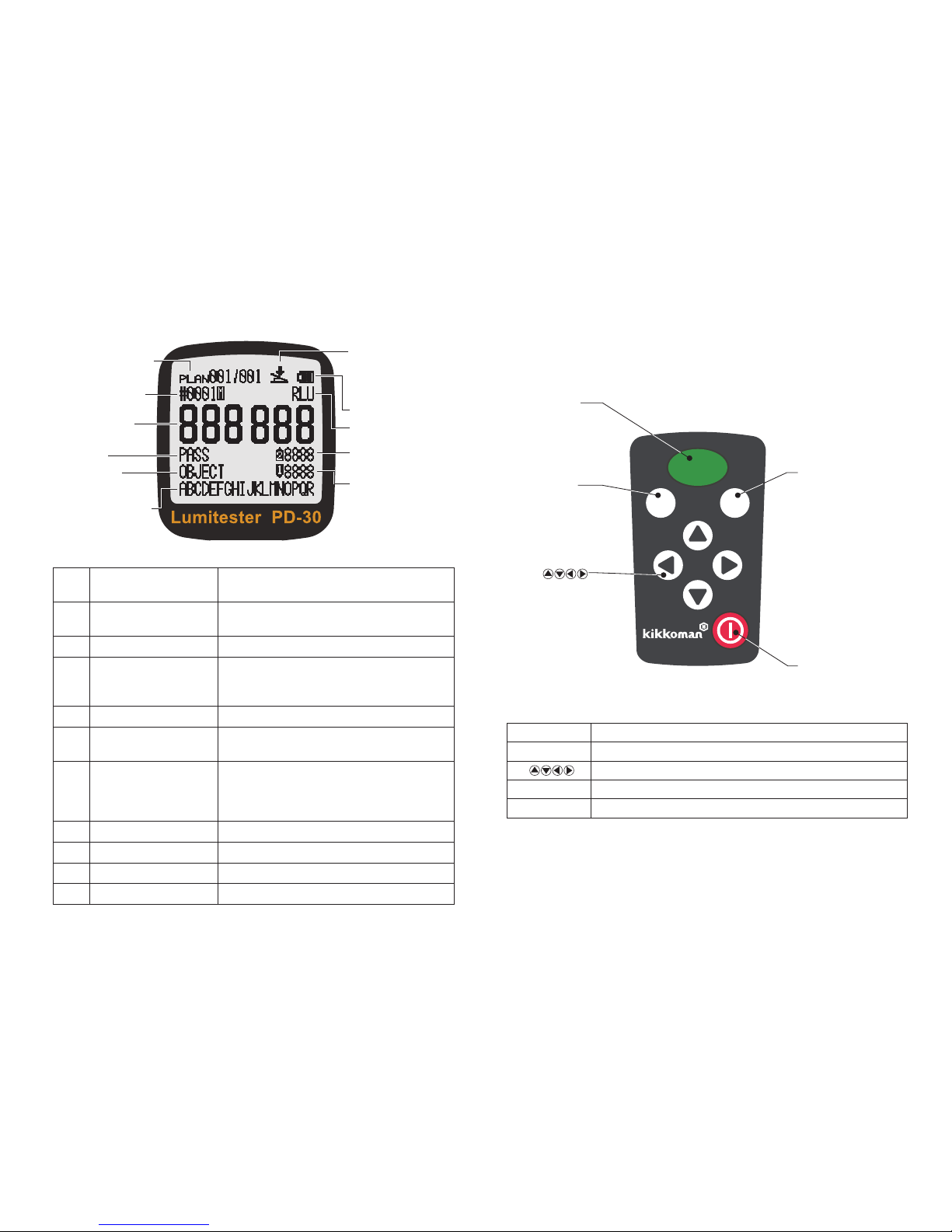
3. Name and Function
3.1 Instrument
3.2 Display panel
3.3 Operation panel
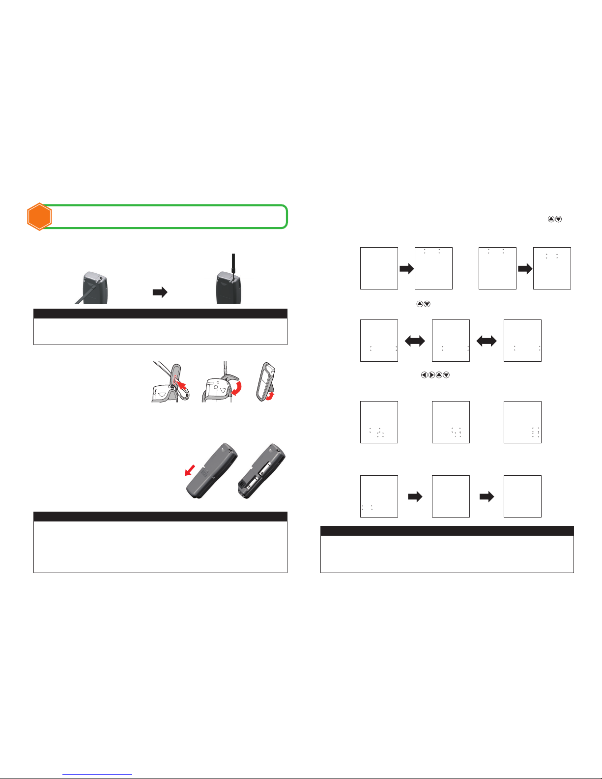
4.Setup
4.1 How to attach the strap
4.2 How to use the case
4.3 How to insert batteries
4.4 Initial power-on setting
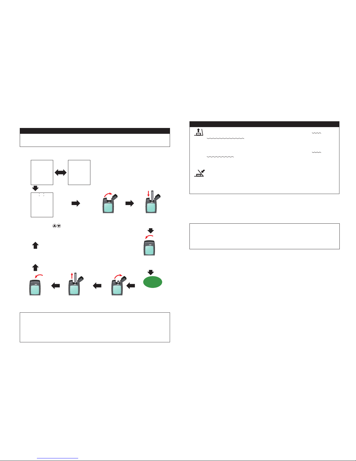
5.Operation Method
5.1 Basic operation
5.1.1 How to turn on the power
5.1.2 MODE measurement and PLAN measurement
5.1.3 MODE measurement
5.1.3.1 Rank judgement
5.1.3.2 Measurement procedure
5.1.4 How to turn o the power
5.2 F (function) setting
5.2.1 Display of memory data
5.2.2 Level Set
5.2.3 Date/Time Set
5.2.4 User selection
5.2.5 Temperature compensation setting
5.2.6 Self-check
5.2.7 Language selection
5.2.8 Memory data clear
5.3 PC connection
6.Maintenance
6.1 Maintenance of the main body
6.2 Maintenance of measurement chamber
6.3 Replacement of batteries
7.Troubleshooting
7.1 Error codes
7.2 Other problems and countermeasures
8.Specications
9.External View
10.After-sales Service
Lumitester PD-30
Instruction Manual
Thank you very much for purchasing the Lumitester PD-30.
All of this Instruction Manual must be read before operation of
this product for safe and proper use.
This Instruction Manual should be kept for future reference.