SKI uFLOW 100LSE-QAL User manual

BA-µflowQAL-en-L-1740.docx
µFLOW 100LSE-QAL
compact calculator for
gas applications
Instruction manual
Valid from software version LSE-QAL-211

2
content
Explanations of symbols _____________________________________________________ 3
General Hints______________________________________________________________ 3
Qualified Personnel_________________________________________________________ 3
Technical data _____________________________________________________________ 4
Dimensions___________________________________________________________________________4
Mechanical mounting___________________________________________________________________4
Cleaning _____________________________________________________________________________ 4
General hints for Electrical connection _____________________________________________________5
Connection examples for inputs___________________________________________________________5
Connection examples for the output________________________________________________________ 5
The terminals in detail __________________________________________________________________6
Choice of function (QAL or LSE) _________________________________________________________7
Exchange of the fuses___________________________________________________________________ 7
The displays _______________________________________________________________ 7
Menu tree _________________________________________________________________ 9
Short example for changing parameter value________________________________________________ 11
Access _____________________________________________________________________________ 11
Sensorbyte –menu point SENSORS (Level C/65) ___________________________________________ 11
k-Factor –Menu point k-factor (level D/7) _________________________________________________ 12
The transfer characteristic ______________________________________________________________ 12
Application of the RS232 Interface _______________________________________________________ 12
Link and control of the µFLOW with a PC _________________________________________________ 12
Adjusting the Baudrate - menu option BAUD (level D/46)_____________________________________ 12
Adjusting the duration of the transmission cycle _____________________________________________ 12
Parameters __________________________________________________________________________ 13
Protocol ____________________________________________________________________________ 13
Data format__________________________________________________________________________ 13
Trouble shooting __________________________________________________________ 14
Description of the failure _______________________________________________________________ 14
Possible reason_______________________________________________________________________14
EC-Declaration of Conformity _______________________________________________ 15

3
Explanations of symbols
Warning of a danger place (caution: consider documentation)
ISO 3864, No. B.3.1
Warning of dangerous electrical voltage
ISO 3864, No. B.3.6
General Hints
For reasons of clarity this manual does not contain detailed information about all types of products and
cannot take into account every conceivable case of installation, operation or maintenance.
If you require further information or should problems occur which are not sufficiently explained in the
manual, you can consult us directly to obtain the necessary information.
May we also draw your attention to the fact that the contents of the manual are not part of a previous or
existing agreement, approval or legal relationship or an amendment thereof. All obligations of the S.K.I.
GmbH result from the contract of purchase which also contains the full and solely valid warranty
agreement. These contractual warranty conditions are neither extended nor restricted by the contents of
the manual.
Qualified Personnel
are persons familiar with the installation, assembly, commissioning and operation of the product and who
have the appropriate qualifications for their activities such as:
Training or instruction or authorization to operate and maintain devices/systems
according to the standard of safety technology for electrical installations.
Training or instruction in the proper care and use of protective equipment in accordance
with appropriate safety practices.
Rendering first aid.
attention
During start up no buttom on the front panel must be pressed
CAUTION
This equipment is a Limit Class A once. It can cause radio disturbance in
residential. On this case costumer has to take care appropriate measure.
This equipment should only be installed and operated after qualified personnel
have ensured that suitable power supply (see name plate) will be used and that
during normal operation or in case of a defect in the system or in components no
hazardous situation can occur. Therefore serious injuries and/or considerable
material damage cannot be ruled out in the event of improper handling of the
device.
The perfect and safe operation of this equipment is conditional upon proper
transport, proper storage, installation and assembly as well as on careful operation
and commissioning.
4
Technical data
indication: LC-Display, 2 lines with 16 signs
nominal voltage: 230 VAC (10%)
115 VAC (optional)
24 VDC (optional)
frequency range: 50 Hz 10%
nominal current: 65 mA @230/115V 50Hz
500 mA @24 VDC
nominal power 15 VA @230/115V 50Hz
12 VA @24 VDC
maximum main interference: 150 V/20 ms, followed by automatic RESET by integrated monitoring
module with backup of the count
EMV tests: according to EN 55011/ 55011-A1; EN 61326-1/ 61326-A1 and
EN 50082-1/2
Functional test: Watchdog, FAIL function with drop-out contact in the event of fault
Available auxiliary power: 24 VDC/160 mA for transmitter supply (with auxiliary power 115/230
VAC only) No transmitter supply is possible with auxiliary power 24 V
DC
analog inputs: 5x 0/4-20 mA switchable via software
1x switchable to Pt100 direct input
measuring range for Pt100: –200°C....+500°C
Internal resistance 24 Ohm per current input, >10 Mfor Pt100
Analog/Digital converter 16 bit resolution with integrated 50Hz-suppression; complete
electrical isolation from the computer and all outputs(except in the
case of transmitter supply)
Frequency input: 0,1 up to 10kHz
Analog outputs: 1x 0/4-20 mA, optional 2x 0/4-20 mA
max. load: 500 Ohm
Contact (open collector): max. 1W, max 30 V
resolution of the outputs: 14 bits, completely electrically isolated from the computer and all
inputs
relay outputs: 1x free configurable, 1x Fail-relay, 1x service relay
max. load of the contacts: 250VAC/8A
*Caution: Before installation and operation costumer has to check the nominal voltage.
Only the declaration on the type plate is guilty!
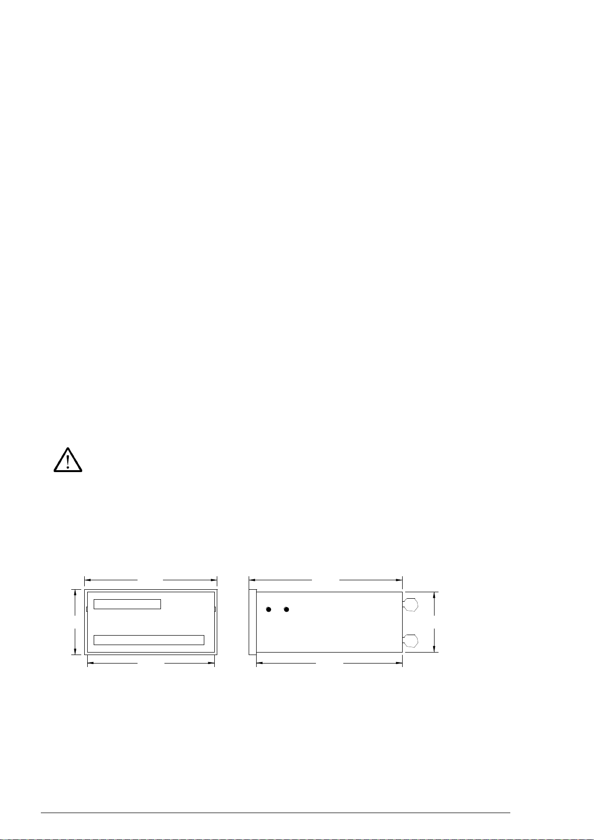
Dimensions
enclosure: glass-fibre-reinforced Noryl, front panel 144x72 mm²(DIN)
material: Noryl SE1 GFN2
protection class: IP 20 (enclosure); IP64 (display unit)
depth: ca. 170 mm
panel cut-out: 5.45“ x 2.7“ (138 x 68 mm²)
5.67“ 6.41“
Mechanical mounting
The standard µflow is a panel mounting unit. After preparing the panel cut-out, costumer has to mount the
µFlow while using the delivered mounting brackets. Please pay attention to use the delivered seal
between panel and µFlow-housing.
Cleaning
The µFlow has to be cleaned only with a dry duster.
65mm
135mm
144mm
72mm
163mm
155mm

5
picture 3: without temperature measurement
picture 4: without pressure
measurement
General hints for Electrical connection
Signal leads must be shielded, one end of the shield has to be connected to mass. Signal
and main leads have to be layed separately.
For electrical installation following determinations are to be observed:
power supply wiring has to be designed for nominal current
power supply has to be installed, so that the power supply of µFlow can be switched off
switch off power supply before opening the µFlow
Connection examples for inputs
Connection examples for the output
picture 6: frequency input for the flow
signal
Picture 5: active signals, the transmitters
are powered by an external
supply.
HE = auxiliary power
picture1: passive current inputs, the
µFlow powers the transmitters
picture 2: passive current inputs, with
Pt100 direct connection instead of
using a temperature transmitter
25
31
µFlow
33
36 o. 37
P
I =
I =
temperatur
e
pressure
k
T
-
+
-
I =
Q
flow
+
+
-
µFlow
press
ure
I =
-
Pt100
P
Q
flow
+
+
I =
-
24
25
26
31
33
36 o.
37
+
P
pressure
-
I =
31
flow
+
Q
-
I =
µFlow
33
36 o.
37
+
tempera-
ture
I =
T
-
flow
+
I =
Q
-
25
36 o.
37
33
µFlow
I =
I =
I =
temperatu
r
T
HE
press
urek
flow
Q
P
HE
HE
-
25
+
-
31
33
+
-
+
µFlow
34o.35
flow
+
Q
-
18
19
µFlow
37
37
37
37

6
Connection examples for outputs
The terminals in detail
Long terminal row short terminal row
terminal
name
use
terminal
name
use
1
L/DC+
Power supply, (24 V DC + optional)
24
B
2
N/DC-
Power supply, (24 V DC - optional)
25
A/IN5
Current input T1 or
3
PE
mass
26
b
4
RXD
Transmit Data
27
B
Limit switches 2 –4 (purging)
TXD
Receive Data
28
A/IN6
Limit switch 1 (operating)
6
DGND
Data Ground
29
b
Power supply for limit switches
7
CNT
contact NPN Open collector
30
IN4
Not used
8
DGND
GND for pulse output
31
IN3
Current input pressure
9
CO
32
IN2
Current input Flow 2
10
NO
Relay 1 (purging relay)
33
IN1
Current input Flow 1
11
NC
34
GND
GND for transmitters
12
CO
35
GND
GND for transmitters
13
NO
Relay 2 (maintenance relay)
36
24V
Auxiliary power for transmitters
14
NC
37
24V
Auxiliary power for transmitters
15
CO
16
NO
Fail-Relay
17
NC
18
Freq+
Frequency input
19
Freq-
20
OUT2-
Analog output 2 (Option)
21
OUT2+
22
OUT1-
Analog output 1
23
OUT1+
picture 7: contact (open collector) for
indicating that the flow velocity
is smaller than the chosen
value of the –Alarm (menu tree,
level 8a).
In this case the voltage drop at
the resistance rises to appr. 24
volts.
picture 8: analog output
outputs are active, there is no need
for an external power supply. The
max. load is 500
Picture 11:main circuit board with
Jumpers for the
frequency input
Picture 12:CPU circuit board with the DIP-
switches for the temperature input
and QAL/LSE
+
-
22(20-OUT2)
23(21-OUT2)
µFlow
Fuse for
24V DC supply
Sof
tw
are
RTD1
or
Temp1
LSE
or
QAL
ON
ON
1
2
1
2
Pt100
Main fuse
Trafo
1
2
3
4
5
6
7
8

7
Choosing the signal for the temperature input (Pt100 or current)
Choosing the software function
Picture 12 shows the location of the DIP switches for the adjustment of the temperature input and the
software function. The switches are reachable after dismounting the back panel. Additional setting for
QAL-Software: Level 54 in the menu tree has to be changed to “extern”.
switch
1
2
Pt100
off
on
Current
on
off
Exchange of the fuses
The main fuse is located on the main circuit board (see picture 11). The fuse for the 24 V auxiliary power
is located on the CPU circuit bord (see picture 11. The fuses are reachable after dismounting of the back
panel. The type of fuse to be used is depending on the power supply
Power supply
Main fuse
Fuse for 24V
230V AC
250V/80 mAT
250V/160 mAT
115V AC
250V/80 mAT
250V/160 mAT
24V DC
250V/0,5 AT
-
Status displays and status signals
Operating
On the next page the displays that can be chosen during a trouble-free operation are shown. The fail-
relay is energized and the maintenance relay is de-energized.
Disabled state
The function of the device is monitored permanently by a „Watch dog”. In case of a malfunction the fail-
relay de-energizes. E.g.: If the supply voltage falls below a permissible value the fail-relay de-energizes
and the display will be darker.
Maintenance
Before carrying out a maintenance both “Prog"-keys have to be pressed simultaneously. The
Maintenance Relay energizes and the following display will be shown:
switch
1
2
LSE
off
off
QAL
on
on
M
a
i
n
t
e
n
a
n
c
e
!
I
D
=
0
0
0
0
8
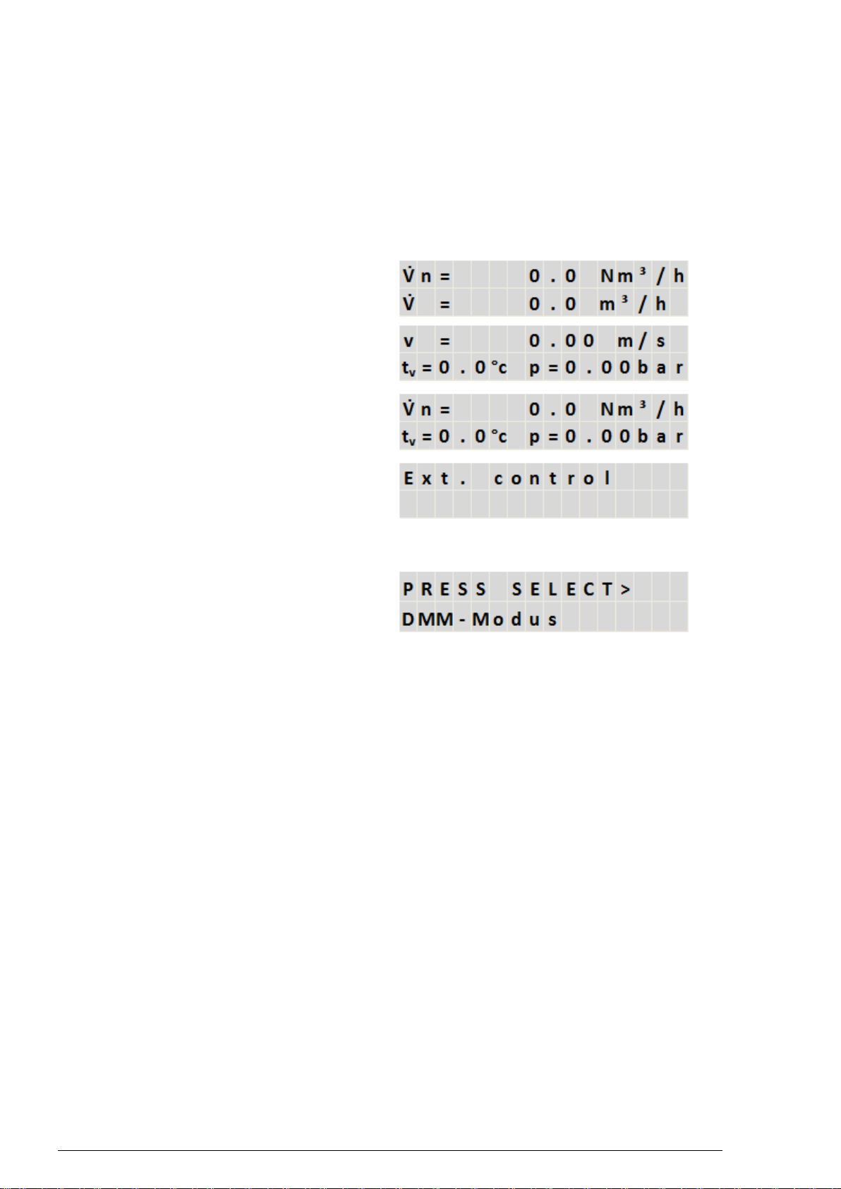
The displays
The following table show the different displays. By pressing the "" key, it is possible to switch between
the displays in descending order of the table. By pressing the "" key, it is possible to switch in the
opposite direction. After pressing the SELECT key, the TAG-no., which can be programmed by the user,
will be indicated. After pressing the SELECT key again, you get back to the normal display mode.
standard volumetric flow
and Actual volumetric flow
flow velocity,
temperature and pressure
standard volumetric flow,
temperature and pressure
air purging device
(ext. switch or time control)
branching of subdisplays for value reading
only available with access for Laboratory, OEM
or Factory
9
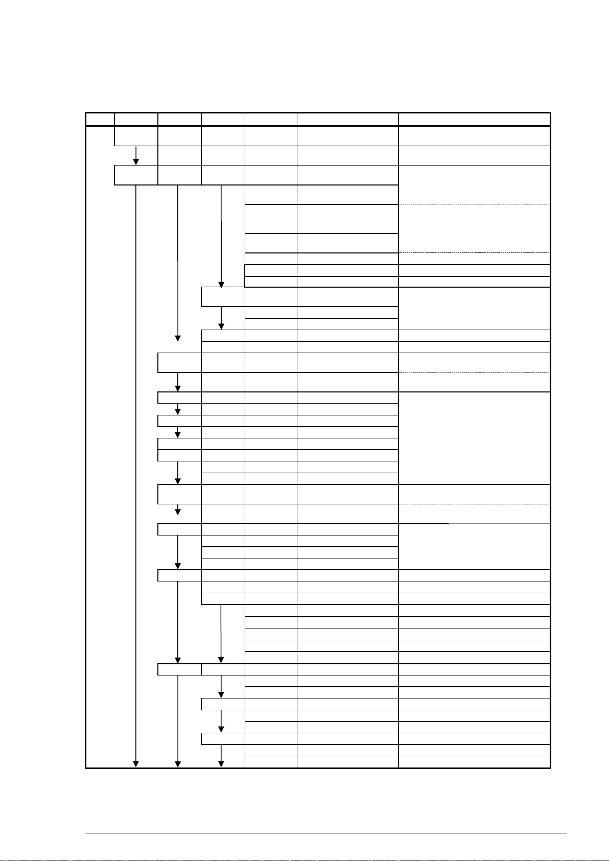
Menu tree
attention: For some parts of the menu the access is denied.
Level
A
B
C
D
Input / indication
comments
1
Info
Version
Ver. GAS-1.9917ff
Indication of the software version, no
input possible
2
Ser.No..
SN: ....
Indication of the serial number, no input
possible
3
Params
Flow1
dp
dP1.min
Input of dP-value for
0/4mA
Does not appear, if a velocity sensor is
chosen
4
dP1.max
Input of dP-value for
20mA
5
dp2.min
Input of dP-value for
0/4mA
Attention: if no second dp- transmitter is
connected, the values for dp2.min +
dp2.max must be set to zero
6
dP2.max
Input of dP-value for
20 mA
7
k-factor
Input of value
Specification of the k-factor
8
density
Input of value
in kg/Nm³
8a
-Alarm
Input of value
0-60 m/s
9
velocity
Puls/V
Input of value
Does not appear, if a dp-sensor is
chosen
10
Vmin
Input of value
Zero point in m³/h
11
Vmax
Input of value
span in m³/h
12
Pipe-ID
Input of value
Internal pipe diameter
13
cutoff
Input of value
cutoff in %
14
Temp
T1.min
temperature according to
0/4mA
15
T1.max
temperature according to
20mA
16
COMP 1
G1min
Input of value
in Vol. %
17
G1max
Input of value
in Vol. %
18
COMP 2
G2min
Input of value
in Vol. %
19
G2max
Input of value
in Vol. %
20
LIMIT
Input of value
in Vol. %
21
density
Rho1
Input of value
in kg/Nm³
22
Rho2
Input of value
in kg/Nm³
23
Rho3
Input of value
in kg/Nm³
24
press
p.min
Pressure according to
0/4 mA
25
p.max
Pressure according to
20 mA
26
RG_DAT
CO2-CON
Input of value
in %
27
N2-CON
Input of value
in %
28
Ho,n
Input of value
in MJ/m³
29
density
Input of value
in kg/Nm³
30
Signal
Damping
Input of value
31
Timebas
Hours, minutes, seconds,
choosing the timebase
32
UNIT
VN
Nm³, Nl
Unit for standard volumetric flow
33
*
VN
Nm³, Nl
Unit for summation of VN
34
m
kg, t, lbs
Unit for mass flow
35
*
m
Kg, t, kt
Unit for summation of m
36
t
°C, K, F
Unit for temperature
37
p
bar, kPa, hPa, psi
Unit for pressure
38
Outputs
Relay1
fnction
VN, V.akt, m, t., p
Function of Relay
39
Charact
min, max
Characteristic of Relay
40
value
Input of value
41
Relay2
fnction
VN, V.akt, m, t., p
Function of Relay
42
Charact
min, max,
Characteristic of Relay
43
value
Input of value
44
Analog1
fnction
VN, V.akt, m, t., p
Function of analog output
45
Charact
4-20, 0-20
Current characteristic
46
Lo-Val
Input of value
Value for 0/4 mA
Only available, if the
process GASKOMP is
chosen in level 75
Only available, if the
process AGA is chosen
in level 75
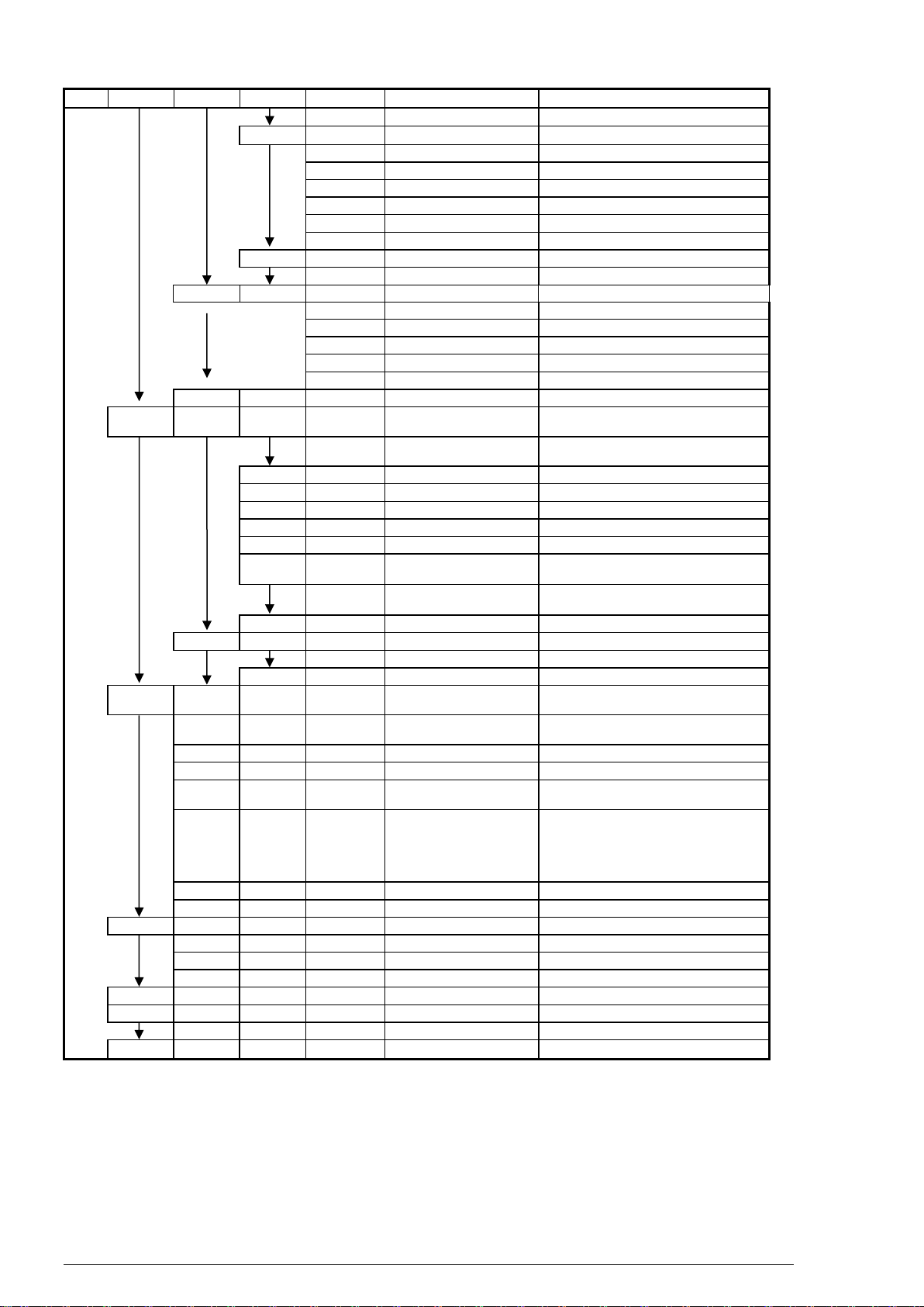
10
Level
A
B
C
D
Input / indication
comments
47
Hi-VAL
Input of value
Value for 20 mA
48
Analog2
fnction
VN, V.akt, m, t., p
Function of analog output
49
Charact
4-20, 0-20
Current characteristic
50
Lo-Val
Wert eingeben
Value for 0/4 mA
51
Hi-VAL
Input of value
Value for 20 mA
52
53
54
55
RS232
Cycle
Input of value
56
Baud
4800, 9600
Baud rate
Purging
Wait
1… 120 sec
Waiting for signal of position indicator
Cycle
0… 6000 min
Duration between purging cycles
Duration
5… 60 sec
Duration of purging
Extern
Extern/timer
External or time triggered control
Level
High/Low
Level for external signal
Pulse Length
1… 20 *10 ms
Pulse length for external signal
57
Tag.No.
Input of signs
Specification of TAG-No
58
calibrt
inputs
IN1
Lo-VAL
Connect 4mA to input,
press ENTER o. Reset
Calibration of current input 1 low value
59
Hi-VAL
Connect 20mA to input,
press ENTER o. Reset
Calibration of current input 1high value
60
IN2
see IN1
see IN1
see IN1
61
IN3
see IN1
see IN1
see IN1
62
IN4
see IN1
see IN1
see IN1
63
IN5
see IN1
see IN1
see IN1
64
IN6
see IN1
see IN1
see IN1
65
RTD1
LO-VAL
Connect 0 to input,
press ENTER o. Reset
Calibration or Pt100 input low value
66
HI-VAL
Connect 330 to input,
press ENTER o. Reset
Calibration or Pt100 input high value
67
RTD2
see RTD 1
see RTD 1
68
outputs
OUT1
DAU-LO
adjustment: 4,0 mA
Output calibration for 4 mA
69
DAU-HI
adjustment: 20,0 mA
Output calibration for 20 mA
70
OUT2
see OUT1
see OUT1
71
Config
Remote
Remote Control
To leave remote control press the
RESET keys
72
Usernam
Input of value
Input of a username by using the arrow
keys
73
Languag
Deutsch, English
Choose language
74
Struct
Sensors
Input of value
Choosing the sensor structure
75
Process
Ideal, AGA, Ethyl,
Gaskomp
Calculation basis for the density
76
Reset
SW-Res, HW-Res, both,
none
Reset of parametrisation and/or
Structure ATTENTION!
new calibration and parametrisation
required
77
Acc_Cnt
N.o.acc.: 21
Account counter
78
In-Byte
Input of value
Choosing inputs as 0..20 or 4..20 mA
79
Factory
SERIAL.
Input of value
Serial number
80
Access
Reset of account counter
81
HW-Byte
Input of value
Selecting the outputs
82
Name
Input of signs
Startup message
83
-Reset
Reset of summations
84
Access
ID-No.
Input of value
Choosing the access
85
Level
list
Choosing the access
86
Measure
Back to normal operation
*internal adders do not have a run over, that means that depending on configuration the value of the
counter can be so high, that it is not possible to indicate the unit and the formula sign. For this reason
it is necessary to reset the adders in time.
11
Short example for changing parameter value
It is necessary for you to change the value of temperature for 20 mA. Follow the short instruction below:
Access
The following table shows the most important ID-codes with the available parts of the menu.
Code
0000
1508
2552
xxxx
xxxx
xxxx
Menu
blocked
worker
Eng.
Labor.
OEM
Factory
INFO
x
x
x
x
x
PARAMS
x
x
x
x
CALIBRG
x
x
x
CONFIG
x
x
FACTORY
x
-RESET
x
x
x
x
x
ACCESS
x
x
x
x
x
MEASURE
x
x
x
x
x
Sensorbyte –menu point SENSORS (Level C/65)
The sensorbyte indicates, which inputs are available and how they can be used.. The following table
should enable you to choose the correct sensorbyte.
inputs
criteria:
0
criteria
1
choose
0 or 1
Bit
temperature 1
Transmitter
PT 100
0
1
0
Temperature 2
Transmitter
PT 100
0
2
0
pressure
Gauge pressure
abs pressure
1
4
4
Flow input 1 kind of sensor
velocity
dp
1
8
8
Flow input 1 signal
rad/current
lin/frequency
0
16
0
Flow input 2 kind of sensor
velocity
dp
0
32
0
Flow input 2 signal
rad/current
lin/frequency
0
64
0
Sensorbyte
=
12
Press simultaneously both PROG-keys. If flow computer has a password, you have to set ID-no..
Programm „2552“. Now you allowed to change most of all menu points (see table below „Access“).
Now press -key. „PARAMS“ is indicated on the left side of display. Press SELECT-key. Press -
key as long as „TEMP1“ is shown on left side of display. Press SELECT-key. Press -key as long as
you can read „TEMP1,max“ on left side of display. Press SELECT-key. Now you can change value of
temperature while using -, -, - and -key. Finish parameter setting while pressing SELECT-
key. Press -key as long as „ENDE“ is shown on left side of display. Press SELECT-key. Press -
key as long as „MEASURE“ is shown on the side of display. Press SELECT-key. Now the flow
computer save parameter changing and starts measuring mode. If you want to protect parameter
mode press both PROG-keys. Then press -key as long as „ACCESS“ is shown on the left side of
display. Press SELECT-key. Press one time -key. Now „LEVEL“ is indicated. Press SELECT-key.
Now „locked“ is shown on the left side of display. Now press SELECT-key. Go to menu-point END
and then MEASURE to leave parameter mode. Now the flow computer is protected to not authorized
programming.
warning: RESET-keys are only in use for factory setting
12
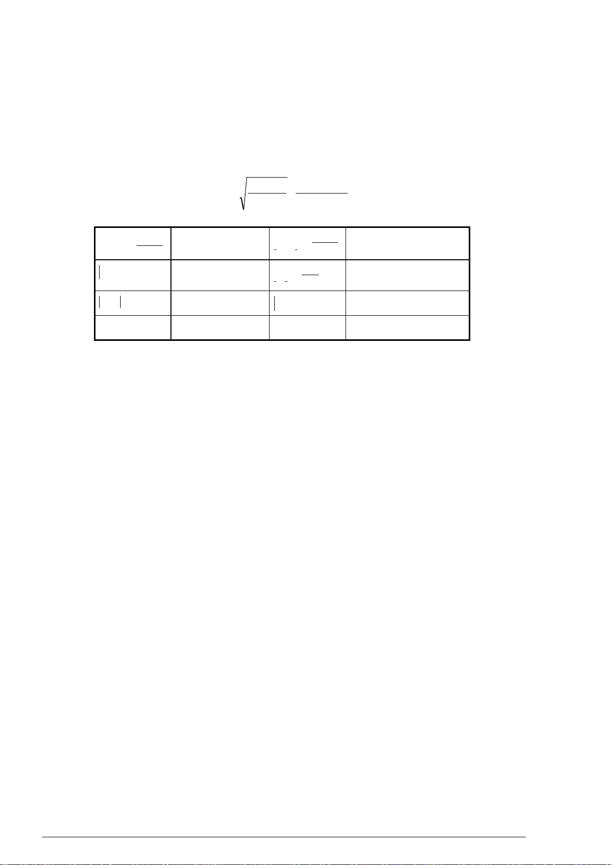
k-Factor –Menu point k-factor (level D/7)
By using an averaging pitot tube, the k-factor of the dp-sensor can be taken from the differential pressure
calculation sheet. For unknown k-factors the value can be calculated by using the following equation.
kT
p p V
D
N A
A
N
i
15 232
,
used units:
VNm
h
N3
Standard
volumetric flow
Nkg
Nm
3
Density at T=273,13K
and p=101,325 kPa
Dmm
i
Internal diameter of
the pipe
kg
m3
Density under operation
conditions
p mbar
Full scale
differential pressure
p kPa
A
Design medium pressure
T K
A
Design medium
temperature
The transfer characteristic
A square rooted or a linear characteristic can be chosen. The µFLOW offers the possibility to link a
second differential pressure transmitter for the extension of the measuring range by measuring point
switching. Under the menu options dp.min. and dp.max. the measuring range boundaries for this second
transmitter can be indicated in the same way as it is already described above for the first transmitter.
Application of the RS232 Interface
The RS232 interface supports data logging.
Link and control of the µFLOW with a PC
The connection between µFLOW and PC is made by a three-core cable with max. 10 m length. The TxD
clamp at the µFLOW is to be connected with the RxD line at the PC interface and the RxD clamp at the
µFLOW with the TxD line of the PC.
The terminal software of the selected COM interface should be adjusted to operation without protocol or
with XON / XOFF protocol. Only if a hardware protocol is intended, the appropriate handshake lines at
the serial interface are to be short circuited.
Adjusting the Baud rate - menu option BAUD (level D/46)
Possible are 4800 and 9600 Baud.
Adjusting the duration of the transmission cycle - menu option CYCLE (level D/45)
The transmission cycle influences directly the developing data flood. Since it concerns with currents in all
rule slow processes, the quantity of data which can be stored should be reduced to a meaningful
measure. The µFLOW therefore supports a minimum interval of 5 seconds.

13
Parameters
According to the transfer parameters selected in the very most applications the µFLOW transmits with
8 data bits
1 stop bit
without parity
with XON / XOFF log
The Baud rate as well as the time between two transfers are adjustable, other parameters are not
adjustable.
Protocol
Due to the low absolute transfer rates it should not come to any conflict in the communication between
µFLOW and PC. Therefore a protocol is actually unnecessary. Nevertheless the transmission activity of
the µFLOW can be controlled by transmitting XOFF by the PC and be continued with XON afterwards
again for all cases. If the interruption should last longer than a transmission cycle, then the data resulting
in the meantime are ignored.
Data format
The µFLOW transmits text character sequences (ASCii) with information about the momentary flow, the
status of the totalizer as well as the primary status data pressure and temperature. The individual values
are separated by blank (ASCii code 32).
A typical line read from left to right could look as follows:
1 2 3 4
1. actual value of the flow in adjusted unit
2. totalizer in adjusted unit
3. temperature in adjusted unit
4. pressure in adjusted unit
The entry and the processing of the measuring data is made according to the standard of the used hard-
and software on the PC.
2436 192873 23.4 101

14
Trouble shooting
Description of the failure
Possible reason
No indication on thr display
Auxiliary power is missing
Main fuse is defective (see page 8)
Instrument does not react on the current inputs
Sensorbyte chosen wrong ( see page 12)
Instrument does not react on the frequency input
Sensorbyte chosen wrong ( see page 12)
Setting of the jumper does not fit to the signal
( see page 6)
Instrument does not react on the Pt100 input
Sensorbyte chosen wrong ( see page 12)
DIP-switches in wrong position ( see page 8)
Auxiliary power for the sensors is missing
Fuse for 24VDC defective (see page 8)
There is no fuse from SN1001
External short circuit
Indicated measured and calculated values are not
realistic
Wrong parametrisation
Output current wrong
Wrong structure 0..20 mA instead of 4..20 mA or
the other way round
Zero or span value wrong
Of course this listing can not be complete. If any mistake occurs, which is not described here, please do
not hesitate to contact us.

15
EC-Declaration of Conformity
according to Article 10.1 of the Directive 2007/108/EEC
(EMC-Directive)
We,
S.K.I. Schlegel & Kremer Industrieautomation GmbH,
Hanns-Martin-Schleyer-Str. 22, 41199 Mönchengladbach
declare in the whole responsibility that the product:
Sensor Unit
__________________________________________________________________
Product
µFLOW
___________________________________________________________________
Type designation and (if necessary) serial number
the requirements under the Council Directive 2004/108/EC to compliance with the laws of Member States
relating to electromagnetic compatibility fulfilled.
The product complies with the requirements of the following guidelines:
EMISSION
EN 55011: 2009 –Limit Class A
(Limits and methods for the determination of electromagnetic radiations of industrial, scientific and
medical (ISM) equipment)
IMMUNITY
EN 61326-1: 2006
(Electrical equipment for measurement, control and laboratory use - Part 1 General Requirements)
- use of the product in residential and industrial areas -
This declaration is based on:
The above mentioned standards have been harmonized and published into the official journal of the EC
Nbr. C59/2011
29.03.2011 Friedhelm Kremer
General Manager

16
S.K.I. Schlegel & Kremer Industrieautomation GmbH
Postfach 41 01 31
D 41241 Mönchengladbach
Hanns-Martin-Schleyer-Str. 22
D 41199 Mönchengladbach
Telefon: +49 (0)2166-62317-0
Web: www.ski-gmbh.com
e-mail: info@ski-gmbh.com
Trademarks and logos are the property of their owners
Subject to technical changes. Illustrations may contain options
Table of contents
Other SKI Test Equipment manuals


Popular Test Equipment manuals by other brands


Risco
Risco VITRON quick start guide

Chauvin Arnoux
Chauvin Arnoux C.A 8220 user manual

Softing IT Networks
Softing IT Networks LinkXpert manual

Gastrolyzer
Gastrolyzer Gastro CH4ECK user manual

Tektronix
Tektronix ths3000 series Installation and safety manual

Kingfisher
Kingfisher KI7347C Series Quick reference guide


