Skil-aire Mini-Spot 1-3T Systems Manual

Mini-Spot 1-3T Systems
Operating and Maintenance Instructions
Cooling Operation
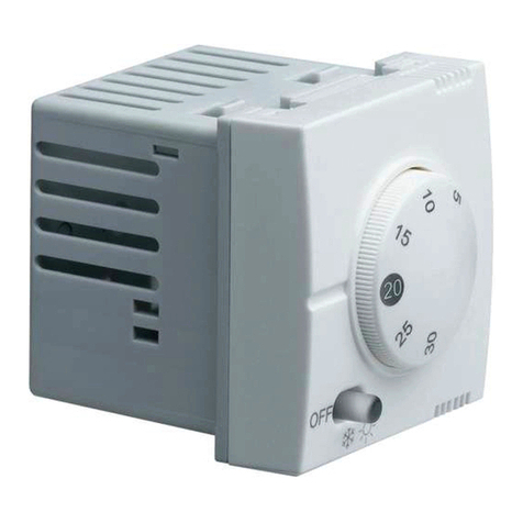
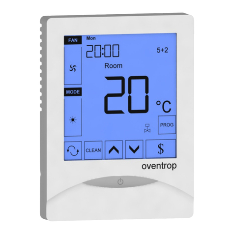
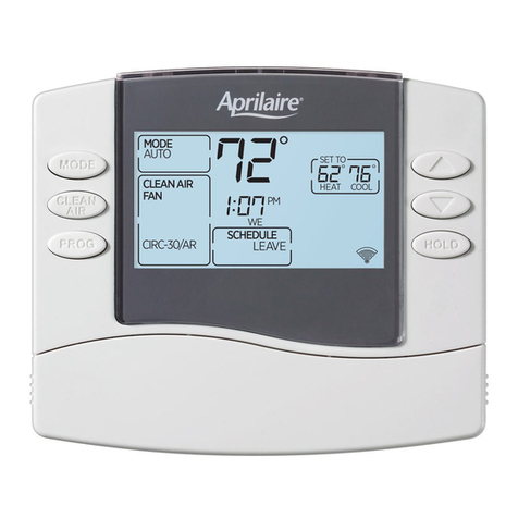
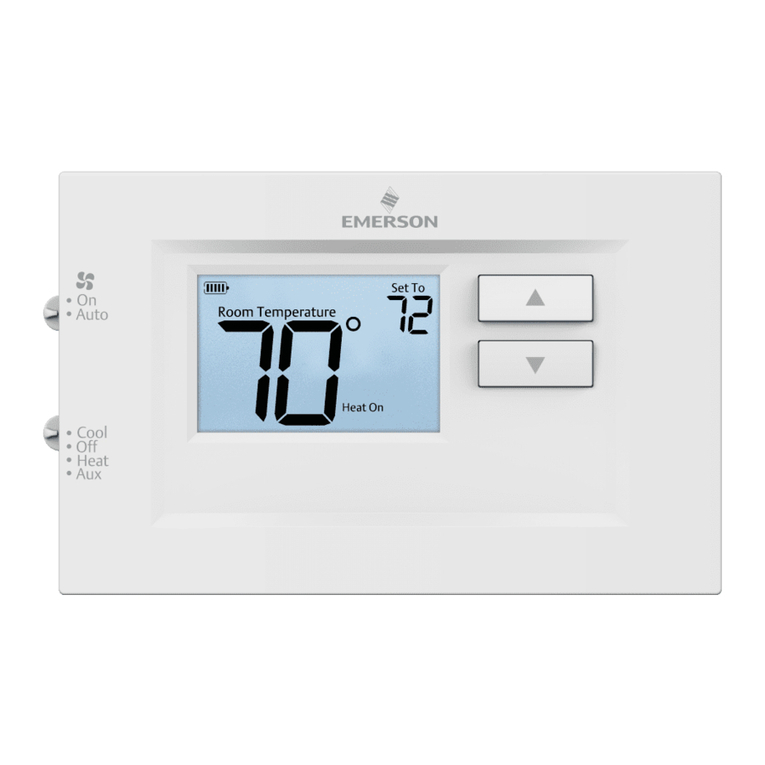
Wall Mounted Thermostat
A wall-mounted thermostat controls the cooling set point. Upon a call for cooling, compressor
contact and evaporator fan relay contacts close. This will energize compressor and
evaporator fan and condenser fan when applicable. As temperature falls below the room set
point, the compressor contacts and evaporator fan contacts will open de-energizing the
system.
Unit Mounted Thermostat
A unit-mounted thermostat controls the set point. Upon a call cooling, compressor contact
relay closes. This will energize compressor and condenser fan when applicable. As the
temperature falls below the room set point the compressor contacts will open.
Fan Operation
Wall Mounted Thermostat
The evaporator fan will operate in either auto or continuous mode, which is controlled by the
thermostat sub-base. In the auto on position, the evaporator fan will run continuously.
Unit Mounted Thermostat
On units with unit mounted thermostats, the evaporator fan relay is kept energized by factory
installed jumper between terminals R & G.
Humidification
When the humidity drops below the set point on the wall mounted humidistat; the auxiliary fan
relay is on if it was off. At the same time, the water solenoid is energized, supplying water to
the evaporator pad When the humidity set point is reached the auxiliary relay and solenoid
valve are de-energized.

INSTALLATION INSTRUCTIONS TO THE INSTALLER
A.) Hanging the unit.
B.) 1) Remove ceiling tile where unit is to be located and remove any adjacent tiles that
would be helpful in handling the unit while positioning it in the ceiling.
2) Secure suitable type material (such as slotted angle) in place. The material should
be capable of supporting the weight of the unit. Now attach all thread rods (3/8”
field supplied) to angle. The rods should have double nuts. See diagram #1 for
spacing of rods to ensure they will line up with hanger when unit is raised into the
ceiling.
3) Next drill holes for hanger positioning screws. Hangers’ positions are marked on
the sides of the units. Do not mount hangers to the unit at this time. Note: if it is
possible to remover one of the 4’ T bar section from the ceiling, then the hangers
can be mounted prior to lifting unit into ceiling.
4) Now raise unit into the ceiling. The use of a high jack is recommended, once unit
is above the ceiling attach mounting brackets to unit and then attach all thread rods
to hangers. Once all thread rods are attached to hangers raise unit several inches
above the ceiling to allow placement of the grille into the ceiling grid. After grille is
in place lower unit just far enough for the frame to form an airtight seal with the
foam backing on the grille. The unit is now ready for electrical wiring or water
piping.
B) Installing Remote Condenser Fan
1) The remote condenser fan can be mounted using a hanger strap or with hangers
provided with the fan and short pieces of angle(field supplied)
2) Prior to hanging the condenser fan section mount the 2x4 junction box to the top of
the unit. Attach wiring harness and connect fan motor wires to the wiring harness
supplied.
3) It is STRONGLY recommended that a field supplied flexible duct connector be
used when attaching condenser section to the evaporator sections.
C) Electrical
All field wiring should be done by a qualified electrician and should meet all local codes.
Knockouts for the unit power, control wiring, and condenser fan are located in the top of the
unit directly above the control section. A wiring harness for the remote condenser fan is
supplied with the unit. The end of the harness with the stacons is attached to the control
section of the unit. Connect the stacons to spade terminal on the main contact on the load
side.

D) Condensate
A ¾” mpt fitting is supplied on each side of the unit. Cap the fitting that will not be used.
E) Water Regulation valve (Water Cooled units only)
Water regulation valves are factory adjusted to maintain an approximate head pressure of
260 lbs psig. If adjustment becomes necessary remove the access panel on the condenser
side and adjust accordingly.
F) Humidifier
The evaporative type humidifier pad is factory installed. Connection of water line and
humidifier water valve is made on control panel side of unit. Humidifier should be connected
to 140 degrees F water supply to insure effective operation.
G) Zone Valve (Chilled Water Units)
A 2 or 3 way water valve is provided with the chilled water unit. This valve is factory installed
and is serviceable through access door adjacent to the control panel. The valve control head
is easily removable for replacement. There is also a manual operation capability built into the
valve to provide temporary operation should control head pressure fail.
H) Low Ambient Control (MAA/D Model Optional)
Low ambient controls that can be provided by means of a pressure activated switch mounted
in the compressor section of the unit. This control is factory adjusted but may be field
adjusted if necessary.
I) Motor Speed
All 2 and 3 ton units are shipped with three speed motors. Changing the motor leads in the
evaporator section of the unit may change the motor speed. Access to leads is through the
access door on the control panel side of the unit. Leads will either be color coded of number
coded.
On units with color-coded leads the colors represent the following speeds: On units with
number coded leads the Number represents the following speeds
YELLOW = COMMON = 1
RED = LOW SPEED = 4
BLUE = MEDIUM SPEED = 3
BLACK = HIGH SPEED = 2
To change the speed of the unit first disconnect power to the unit. Disconnect speed now in
used and cap this lead with suitable device. Reconnect lead from fan relay to speed desired.
Note 1: On units that have both humidifier and reheat the auxiliary relay is omitted and a
jumper is installed between terminals (R) and (G).
Note 2: 140 degrees domestic hot water should be supplied to humidifier in order to satisfy
rated capacity.
Note 3: a small plastic orifice installed between the solenoid valve and the evaporator pad
regulates the water flow.
Note 4: the humidistat and dehumidistat can either be wall mounted or unit mounted.

DEFROST CONTROL FOR HEATPUMP UNIT
The Skil–Aire heat pump utilizes a defrost system controlled by a temperature sensing
device. The defrost cycle initiates when the bulb attached to the outdoor coil senses a
temperature of 30 F or less. This means that the unit (when in the heating cycle) will go into
a defrost cycle only id the outdoor coil is cold enough to accumulate frost. The defrost cycle
ends when the outdoor coil temperature rises to 80 F.?
DE-HUMIDIFICATION AND REHEAT
(Wall Mounted thermostat)
Upon an increase in humidity beyond the set point on the wall mounted de-humidistat the
cooling cycle is energized. The unit will remain in cooling until the humidity level in the room
reaches the set point on the de-humidistat. If the room temperature falls below the set point
on the room thermostat the reheat coil will energize to offset the cooling effect of the de-
humidification cycle. There must be at least a low load in the room to maintain room
temperature.
(Unit Mounted thermostat)
On units with a unit mounted thermostat the reheat is controlled by the same thermostat that
controls the cooling cycle. Reheat can not be energized except when there is a call for de-
humidification which functions the same as the units with wall mounted controls.
SYSTEM SAFETIES
The unit has several inherent safety devices. High and Low pressure switches are an
integral part of the refrigeration system. Should an unsafe high and or low-pressure condition
exist the appropriate safety device will trip. Condensate overflow switches are installed on
the drain pan of each unit. There are two switches and should the condensate level rise to
an unsafe level the switches will cause the unit to shut down operation. This is accomplished
by interrupting the low voltage power supply from the 24-volt transformer. Both compressor
and fan motor have an internal automatic reset safety, which is the thermal type.
MAINTENANCE
Filter Changes: The unit is supplied with a 20 x 20 x 1 disposable filter. Access to
the filter is through the hinged return air grille. This filter should be
changed a minimum of four times per year. A higher frequency of
filter changes may be necessary depending on the area where the
unit is installed.
Fan motor Lubrication: The evaporator fan motor should be oiled once per year using a
SAE#10 or SAE#20 non-detergent oil. There are oil ports at each
end of the motor.
Evap. and Cond. Coil: Clean both coils with a stiff brush. Be careful of the coil fins due
to the fact that they are razor sharp. After brushing use a vacuum
or compressed air to clean away brushed off dirt.
Remote Condenser Coil: Clean coil as stated above or use low pressurized water or steam.
Condensate pan & Drain: Check and clean on a bi-monthly basis.
Humidifier: Check canister on a bi-monthly basis for material builds up,
replaces as required.

Reheat: Reheat units have a tendency to collect minute dust/dirt particles.
When energized, these particles will burn off. Energize reheat
during normal maintenance procedures. NOTE: disable halon
system to prevent possible discharge during reheat test.
CHARGING PROCEDURE
Before charging make sure that no air was allowed to enter the system. If pre charged tubing
was not used evacuate the system completely and check for leaks. When charging the unit
do not use liquid refrigerant in the suction side. Charge with vapor refrigerant only. A manual
shut-off valve is provided between the receiver and expansion valve. By shutting off this valve
charging the system can be accomplished faster. Be sure to open the valve when charging is
completed.
Note: The low-ambient refrigerant control valve will bypass whenever the head pressure is
lower than 220 psig. This is normal.
AIR COOLED UNITS- REFRIGERANT LINE SIZING
Unit tonnage CircuitLiquid Drain Line Hot Gas Line
1 1 ½”½”
2 1 5/8”7/8”
3 1 5/8”7/8”
1) Each circuit will have a liquid drain line and a hot gas line.
2) The liquid line is an n oversized liquid line that runs between the condenser and receiver
(unit). Its size allows vapor in the receiver to return to the condenser against the flow of
liquid refrigerant.
3) On horizontal runs the hot gas line should be pitched downward in the direction of flow ½”
for every ten feet (10 ft)
4) On vertical rises the hot gas line should be trapped every twenty feet (20 ft)
5) Refrigerant lines should be properly supported to avoid pulsation vibrations.
6) Avoid running refrigerant lines in areas where low noise levels are required.
AIR COOLED UNITS –REFRIGERANT CHARGE
The tables below indicate the amount of refrigerant required per circuit to adequately operate
the unit. Please note; if you are charging the unit in a warm ambient condition not all of the
recommended charge is needed to operate the unit at that condition. However, all the
recommended charge must be used in order for the equipment to operate properly the year
round.
1) Basic Unit charges
Unit tonnage Circuits Charge per circuit (lbs)
1 1 5
2 1 8
3 1 11

2) Interconnection pipe charge
For split-systems you need to consider the refrigerant charge being held in the
interconnection piping (liquid drain line, hot gas line). The amount of charge
held in the hot gas line is minimal. Therefore, we will consider only the liquid
line for calculation purposes.
Liquid line size copper tubing Charge per circuit
½” O.D. .7 lbs/10 ft
5/8” O.D. 1.2 lbs/10 ft
7/8” O.D. 2.4 lbs/10 ft
3) Total Charge
To calculate the total charge, add one (1) the basic unit charge and two-(2)
piping charge. Remember the amounts given above are per circuit
IMPORTANT
If your unit is equipped with a
CANISTER HUMIDIFIER:
The canister must be changed approximately one to two times per year.
Please call
1-800-625-SKIL
For parts and information.
Please have your model number ready:
For 208/230 volts, use model #102
For 460 volts, use model #104
FU INFORMATION
Warning the manufacturer’s warranty does not cover any damage or defect to the air
conditioner caused by the attachment of use of any components, accessories or
devices (other than those authorized by the manufacturer) into, onto or in conjunction
with the air conditioner. You should be aware that the use of unauthorized
components, accessories or devices may adversely affected the operation of the air
conditioner and may also endanger life and property. The manufacturer disclaims any
responsibility for such loss or injury resulting from the use of such unauthorized
components, accessories or devices
GENERAL
The information contained in this manual has been prepared to assist in the proper
installation, operation and maintenance of the air conditioning system. Improper
installation, or installation not made in accordance with these instructions, can result in
unsatisfactory operation and/or dangerous conditions, and can cause the related
warranty not to apply.
Read this manual and any instructions packaged with separate equipment required to
make up the system prior to installation. Retain this manual for future reference. To
achieve unit design operation efficiency and capacity, the indoor cooling coils listed in
the condensing unit specification sheet should be used.

CHECKING PRODUCT RECEIVED
Upon receiving unit, inspect if for any shipping damage. Claims for damage, either
apparent or concealed, should be filed immediately with the shipping company. Check
condensing unit electrical characteristics and accessories to determine if they are
correct. Check system components (evaporator coil, condensing unit, evaporator
blower, etc. to make sure they are properly matched.
Remove shipping bracket under compressor if supplied. With the thermostat in the
“Off” position, turn the power on to the furnace and the condensing unit. Before
starting condensing unit allow 12 hours time to elapse, giving the crankcase heater (if
provided) time to drive refrigerant from the compressor, thus preventing damage
during start-up. Start the condensing unit and the furnace with the thermostat. Make
sure the indoor air handler is operating.


Table of contents
