Skipper DL850 Specification sheet

Document no: DM-D002-SC Rev 4.03.00A
Edition: 20110624
SKIPPER Electronics AS Telephone: +47 23 30 22 70
Enebakkveien 150 Telefax: +47 23 30 22 71
P. O. Box 151, Manglerud E-mail: support@skipper.no
0612 Oslo, Norway Co. reg. no: NO-965378847-MVA
www.skipper.no
DL850 (270 kHz)
Operation and Installation Manual
2 Axis Doppler Speed Log

Version: 20110624Sw: 04.03.00Page 2 of 80
SKIPPER Electronics AS DL850 270 kHz Operation and Installation
Important: During installation, DO NOT CUT THE TRANSDUCER CABLE.
The transducer, transducer cable and transceiver cabinet are all “balanced parts”. Therefore
cutting the cable may deteriorate performance and will also void the warranty.
Weitergabe sowie vervielfältigung dieser unterlage, verwertung
und mitteilung ihres inhaltes nicht gestattet, soweit nicht
ausdrücklich zugestanden. Zuwiderhandlungen verpflichten zu
schadenersatz.
Toute communication ou reproduction de ce document,
toute exploitation ou communication de ou son contenu sont
interdites, sauf autorisation expresse. Tout manquement à
cette règle est illicite et expose son auteur au versement de
dommeges et intèrèts.
Copying of this document, and giving it to others and the use
or communication of contents thereof, are forbidden without
express authority. Offenders are liable to the payment of
damages.
Sin nuestra expresa autorización, queda terminantemente
prohibida la reproducción total o parcial de este documento,
asì como su uso indebido y/o su exhibición o comunicación
a terceros. De los infractores Se exigirá el correspondiente
resarcimiento de daños y perjuicios.
Information:
Please visit our web site www.skipper.no for additional information. Here you will find
product bulletins, software updates, instruction manuals, installation procedures etc.

Version: 20110624 Sw: 04.03.00 Page 3 of 80
Contents
1. INTRODUCTION..................................................................................6
System Summary ..........................................................................................................6
Sensor (Transducer) and Transceiver............................................................................6
Operator Unit ................................................................................................................7
Interfacing.....................................................................................................................7
Outputs ...........................................................................................................................................7
Inputs..............................................................................................................................................7
Alarms ............................................................................................................................................7
2. OPERATION........................................................................................10
Parameter entry ...........................................................................................................10
Primary Screens ..........................................................................................................11
Screen pilot, Menu 1, trip/speed alarm. .......................................................................................12
Screen pilot, Menu 2, system. ......................................................................................................13
Screen shallow water, (only in non docking version). .................................................................14
Screen docking, arrow view (only in docking version). ..............................................................15
Screen docking, bar graph view (only in docking version)..........................................................16
Screen open sea, system...............................................................................................................17
Setup and Function Control Screens...........................................................................18
Screen com, Menu 1, NMEA setup..............................................................................................19
Screen com, Menu 2, NMEA com setup......................................................................................20
Screen status, Menu 1, units.........................................................................................................22
Screen status, Menu 2, date/time..................................................................................................23
Screen status, Menu 3, boat setup/buzzer.....................................................................................23
Screen status, Menu 4, pulse settings...........................................................................................24
Screen status, Menu 5, analogue settings.....................................................................................24
Screen status, Menu 6, speed limits and hysteresis......................................................................25
Screen status, Menu 7, signal good/signal suspected...................................................................25
Screen status, Menu 8, speed test/demo (simulate)......................................................................25
Screen calibration, Menu 1, calibration. ......................................................................................26
Screen calibration, Menu 2, manual override. .............................................................................27
Screen calibration, Menu 3, mounting settings............................................................................27
Screen diagnostics, Menu 1..........................................................................................................28
Screen diagnostics, Menu 2, filtering/averaging. .........................................................................29
Screen diagnostics, Menu 3, settings ...........................................................................................29
Principal Functions ....................................................................................................30
Doppler Log Principle..................................................................................................................30
Water Track Characteristics..........................................................................................................30
Echo sounder option.....................................................................................................................30
Non-volatile Parameter Memory..................................................................................................31
Fixed Key Functions...................................................................................................31
Screen Select ................................................................................................................................31
Backlight adjustment (brightness)................................................................................................31
Day/Night.....................................................................................................................................31
DL850 270 kHz Operation and Installation SKIPPER Electronics AS

Version: 20110624Sw: 04.03.00Page 4 of 80
Soft Key Functions .....................................................................................................32
Speed limits functionality.............................................................................................................32
3. USER MAINTENANCE.....................................................................34
Transducer Maintenance .............................................................................................34
Operator Unit and Transceiver Unit Maintenance ......................................................34
4. INSTALLATION .................................................................................35
Handling warning........................................................................................................35
Transducer Installation................................................................................................36
Location........................................................................................................................................36
Operator Unit Installation ...........................................................................................36
115/230 V selection on Combo Terminal board...........................................................................36
AC Voltage selection ....................................................................................................................37
Fuses.............................................................................................................................................37
Back-up Battery Jumper JP200....................................................................................................38
Power indication and function LEDs ...........................................................................................39
Interfacing...................................................................................................................41
Alarm relay...................................................................................................................................41
Log Pulse Outputs ........................................................................................................................41
Inputs............................................................................................................................................42
Analogue interfaces......................................................................................................................42
NMEA interface ...........................................................................................................................42
Options........................................................................................................................42
Repeaters/Slaves...........................................................................................................................42
External Interface Ports................................................................................................................43
Operator Unit - Connecting External Equipment .......................................................44
Operator unit - Terminal connections .........................................................................45
Misc I/O connections .................................................................................................46
Alarm connections .....................................................................................................47
5. START-UPAND SYSTEM ADAPTION............................................48
System Adaption .........................................................................................................48
Analogue outputs and log pulse outputs range selection .............................................................48
Units of Measure ..........................................................................................................................48
NMEA Setup ................................................................................................................................48
Doppler log transmitted (talker) (IEC 61162-1:2007(E) (NMEA 0183) messages .....................49
Docking option parameter setup ..................................................................................................50
6. CALIBRATION PROCEDURE ........................................................51
Calibration routine: ......................................................................................................................52
Activation of the hidden menus ..................................................................................................52
Step 1. Heading error correction: .................................................................................................53
Step 2a. Manual speed calibration/adjustment:............................................................................53
Step 2b. Semi Automatic calibration: ..........................................................................................54
SKIPPER Electronics AS DL850 270 kHz Operation and Installation

Version: 20110624 Sw: 04.03.00 Page 5 of 80
7. TROUBLE SHOOTING.....................................................................56
Basic System Integrity ................................................................................................56
Installation problems...................................................................................................57
Interface problems ......................................................................................................58
Basic functionality ......................................................................................................58
Typical Status Screen Contents...................................................................................59
Typical diagnostic screen contents..............................................................................61
Master reset procedure................................................................................................64
8. SPECIFICATIONS..............................................................................65
Dimensions .................................................................................................................65
Functional Properties ..................................................................................................65
Performance ................................................................................................................66
Environmental.............................................................................................................66
9. SERVICE..............................................................................................67
10. APPENDIX 1......................................................................................68
Miscellaneous Installation Diagrams..........................................................................68
PCB positions in Transceiver Unit ...............................................................................................69
LEDs on PCBs in Transceiver Unit..............................................................................................70
DL 850 System Overview ............................................................................................................71
Operator Unit - Transceiver Unit Interconnection .......................................................................72
270 kHz Sensor Cable Connection...............................................................................................73
Transceiver Unit Dimensions.......................................................................................................74
Dimensional Drawing Cabinet.....................................................................................................75
115/230 V selection on backplane inside Transceiver unit ..........................................................76
12. APPENDIX 2......................................................................................77
Upgrading Software .....................................................................................................................77
CPU PCA-6742VE setup .............................................................................................................78
13. APPENDIX 3......................................................................................79
The echo sounder function ...........................................................................................................79
Screen Pilot, Menu 1, trip/speed alarm. .......................................................................................79
Screen Pilot, Menu 2, ES mode settings. .....................................................................................80
Screen diagnostics, Menu 3, ES mode, SL BT mode, GPS->BT.................................................80
DL850 270 kHz Operation and Installation SKIPPER Electronics AS

Version: 20110624Sw: 04.03.00Page 6 of 80
1. Introduction
System Summary
The system is a navigation, 2 axis (transversal and longitudinal) Doppler speed log with a large
LCD. The display graphics is continuously shown on the LCD along with available navigation
details. Comprehensive interfaces are available including IEC 61162-1:2007(E) (NMEA 0183) input
and output. All IMO (International Maritime Organization) requirements for speed logs are met or
exceeded.
Sensor (Transducer) and Transceiver
The Doppler sensor consists of a head with hydro-acoustic elements. Two different versions of the
sensor head (270 kHz and 540 kHz) exist, both with 2 axis log function. The 540 kHz, has in addition,
one extra element for the auxiliary echo sounder option. The sensor is connected to a transceiver
cabinet located within 40 m of the sensor.
The connection from the transceiver cabinet to the operator unit is via a serial RS-422 data link and
may be up to 1000 m. Transceiver and operator unit power supply options are 115/230 V AC or 24 V
DC. The power consumption for the transceiver unit is app. 80 Watt at 115/230 V AC or 60 Watt at 24
V DC.
Three beam transducer (270 kHz)
ab
3 dimensional view Seen from above
Five beam transducer (540 kHz)
ab
3 dimensional view Seen from above
(Transversal)
B1
B1
B2
B2
B3
B3 120
o
240
o
(Transversal)
B1
B1
B3
B3
B4
B2
90
o
180
o
B4
270
o
B5 B2
B5
(Longitudinal)
(Longitudinal)
(Fore)
(Aft)
(Starboard)(Port)
(Starboard)(Port)
(
Fore
)
(Aft)
SKIPPER Electronics AS DL850 270 kHz Operation and Installation

Version: 20110624 Sw: 04.03.00 Page 7 of 80
Operator Unit
The operator unit contains a graphic LCD display and a keyboard with fixed keys, softkeys and a
rotating encoder. The function of each softkey button depends on the active screen, and the buttons are
labelled on the lower rim of the LCD. The display is back lit, and back light intensity may be adjusted
by the user. Various user-selectable information layouts adapted to typical operational situations,
may be displayed continuously on the LCD. The operator unit can be flush mounted, wall mounted
or bracket mounted. Operator unit power supply options are 115/230 V AC or 24 V DC. The power
consumption is app. 70 Watt at 115/230 V AC or 50 Watt at 24 V DC.
Interfacing
The display unit has various interface possibilities.
Outputs
• 3 log outputs 10/100/200/400/1000 pulses per nautical mile.
• 2 outputs also gives speed direction.
• 3 analogue outputs 0 - 10 V or 4 - 20 mA.
• IEC 61162-1:2007(E) (NMEA 0183) interface output of speed/distance, temperature, alarm and
depth information.
• Functional alarm relay.
• Power failure alarm.
• Speed limit alarm.
• External VGA monitor.
Inputs
• IEC 61162-1:2007(E) (NMEA 0183) interface input for alarm, position, rate of turn, heading and
UTC (Coordinated Universal Time).
• External alarm reset.
Alarms
High and low speed alarms may be selected from the menus (screen pilot, menu 1). Alarms are
provided on both a potential free relay contact and as NMEA messages. Both ways can be used for
interface to external alarm systems. An optocoupler output is used as a separate output for power
failure alarm.
DL850 270 kHz Operation and Installation SKIPPER Electronics AS

Version: 20110624Sw: 04.03.00Page 8 of 80
ENCODER
BRIGHTNESS
DAY / NIGHT
SCREEN SELECT
SOFTKEYS
SOFTKEY
TEXTS
GRAPHICS
Fig. 1.1 Operator unit, panel layout.
SKIPPER Electronics AS DL850 270 kHz Operation and Installation

Version: 20110624 Sw: 04.03.00 Page 9 of 80
Fig. 1.2 System Diagram
Navigator
Gyro
Computer system
Cabinet
Analogue speed and direction output
0 -10 V/4 - 20 mA
115/230 VAC/24 V DC
2 x 2.5 sq. mm
screened
yard supply
NMEA 0183
NMEA 0183
NMEA 0183
Hull
External alarm reset
Standard supply except yard supply cables
1 pair each
xducer,
2.5 sq. mm
screened
yard supply
Pulse output
Optional remote VGA and/or
LCD monitor
Speed alarm
SB Gate Valve
NMEA 0183 Repeater
IR300
Logging to Compact Flash card
Transceiver Unit
Combo Tank
Steel
Pipe
(Yard Supply)
DL 850
50
MADE IN NORWAY
Power failure alarm
DB Gate Valve
4 tsp 0.325
sq.mm
max 1000 m
DL850 270 kHz Operation and Installation SKIPPER Electronics AS

Version: 20110624Sw: 04.03.00Page 10 of 80
2. Operation
When the installation is complete, and power is connected to the operator unit, the system is switched
on/off by a power switch inside the cabinet. The unit can also be switched off by pressing the system
OFF softkey button.
Note: The unit is still energized. Do not perform any connections before switching off the mains
on the terminal PCB inside the cabinet.
Parameter entry
The fixed function buttons and the softkey buttons along with the rotating encoder, facilitates entry of
parameters and other data. The following flowchart illustrates the procedure for changing settings. The
various screens are shown in detail in the operation section.
Fig. 2.1 Setting and Parameter Entry Flowchart
Example of parameter entry
Suppose you want to enter a value of 15 knots for the high speed alarm. Press the SPD ALARM
softkey in screen pilot, menu 1, and keep it pressed while you turn the encoder until you reach 15 knots.
Release the encoder and release the SPD ALARM softkey.
Any
Screen
Rotate encoder
in either
direction to
obtain desired
state or setting
Check for
desired result
Any valid fixed or
soft key
Advances to next
fixed state or
value
PRESS
BUTTON
ONCE
KEEP
BUTTON
PRESSED
RELEASE
BUTTON
SKIPPER Electronics AS DL850 270 kHz Operation and Installation
Version: 20110624 Sw: 04.03.00 Page 11 of 80
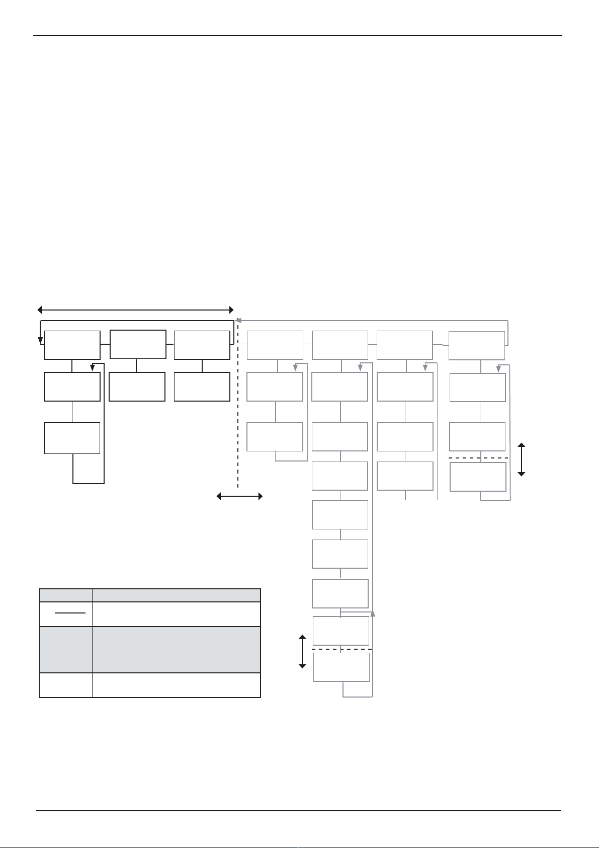
Primary Screens
Each of the operation screens contains a graphic picture and one or more menu sets configured on
the 6 softkey buttons. The three first screens are covering the primary functions. Manoeuvring within
these screens are easily done by pressing the screen select button.
The various screens can also be selected by keeping the screen select button pressed and rotating the
encoder in either direction. Turning the encoder clockwise cycle the screens as shown in figure below,
and counter clockwise rotation cycles the screens in the opposite direction.
The screen layouts are outlined in the following pages. The various menus and softkey functions are
described with each screen
PILOT OPEN SEA COM STATUS CALIB
2. System On/
off
1. Trip/Speed-
alarm
2. Manual
override
3. Mounting
settings
4. Pulse
settings
3. Boat setup/
Buzzer
5. Analogue
settings
8. Speed test/
Demo
2. COM setup
1. Units
1. System On/
off 1. NMEA setup
2. Date/Time
1. Calibration
*
*
1. Docking
views
SHALLOW/
DOCKING
Primary Screens
*
Symbol Description
Normal route using SCREEN SELECT
button.
- - - - - - - Use SCREEN SELECT button and encoder
to get past “barrier” and get access to
screen COM, STATUS, CALIB, and
DIAGNOSTICS
* Use “hidden” button on keyboard to enable
options.
Barrier
Note: Use SCREEN SELECT button
and the encoder to pass the barrier.
DIAGNOSTICS
1. On/off
**
6. Speed limit/
Hysteresis
Barrier
7. Signal good/
Suspected
2. Filter
*
3. Settings
Barrier
DL850 270 kHz Operation and Installation SKIPPER Electronics AS

Version: 20110624Sw: 04.03.00Page 12 of 80
The various softkey menus are selected by pressing repeatedly the MENU button on the left side of the
softkey menu. The number on the button indicates present active menu.
• “Brown” is speed over ground.
• “Blue” is speed through water.
• Drift angle is the angle between the longitudinal axis and resultant speed vector.
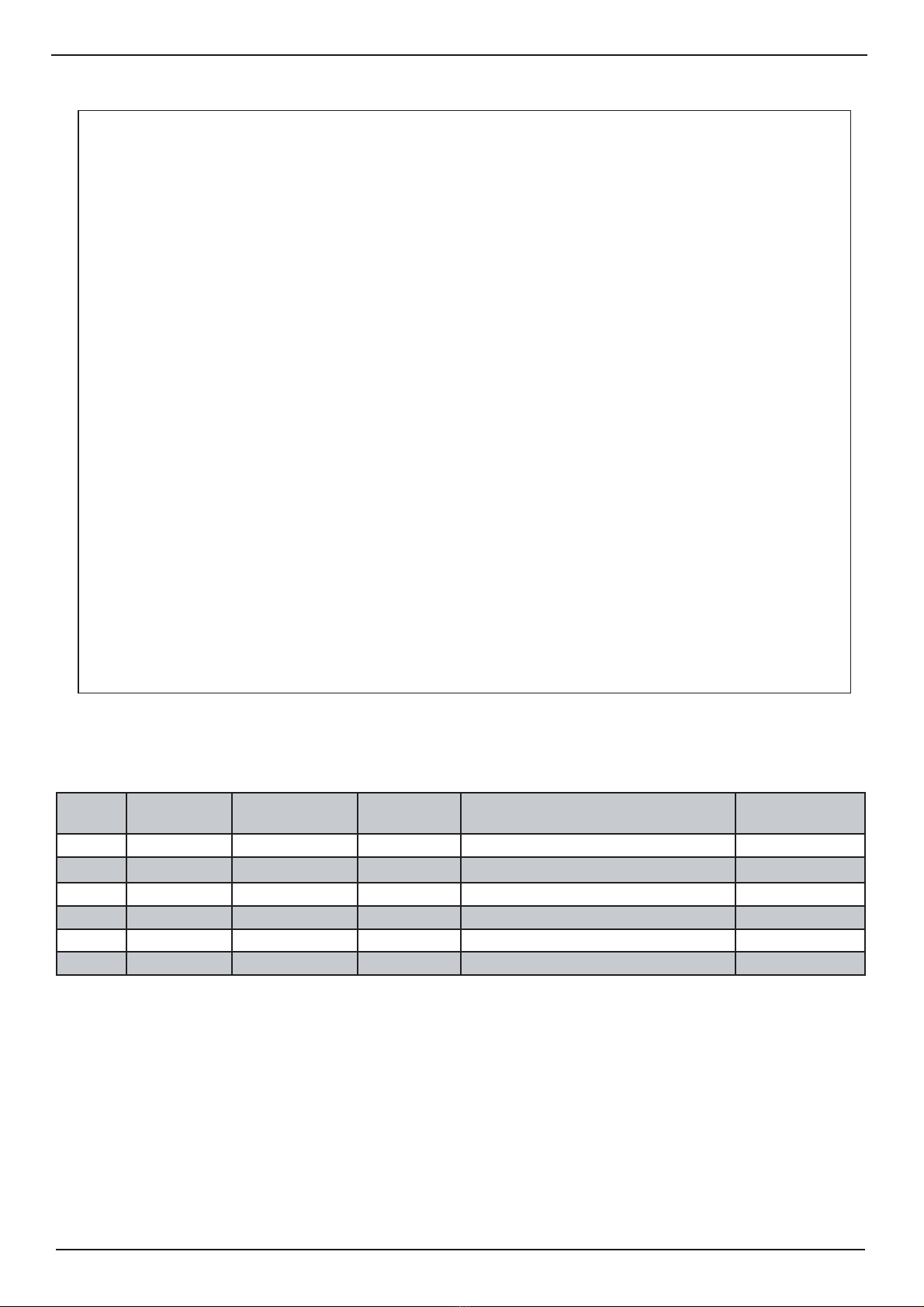
Screen pilot, Menu 1, trip/speed alarm.
Softkey Name Range/value Default value Description Activate with
hidden button
1 MENU 1 - 2 1 Menu 1 is selected.
2 Not used.
3 TRIP Reset Trip distance counter reset.
4 SPD ALARM -48.4 - 48.6 kn 20.0 kn High speed alarm.
5 SPD ALARM -48.6 - 48.4 kn 0.0 kn Low speed alarm.
6 SYSTEM On/Off On Turn system off.
SKIPPER Electronics AS DL850 270 kHz Operation and Installation
Version: 20110624 Sw: 04.03.00 Page 13 of 80
The various softkey menus are selected by pressing repeatedly the MENU button on the left side of the
softkey menu. The number on the button indicates present active menu.
Screen pilot, Menu 2, system.
Softkey Name Range/value Default value Description Activate with
hidden button
1 MENU 1 - 2 2 Menu 2 is selected.
2 Not used.
3 Normally not used. (See appendix 3).
4 Not used.
5 Not used.
6 SYSTEM On/Off On Turn system off.
DL850 270 kHz Operation and Installation SKIPPER Electronics AS

Version: 20110624Sw: 04.03.00Page 14 of 80
• Screen description “blue” shows resultant water speed and direction.
• Screen description “brown” shows resultant SOG (speed over ground) and direction. (Note: Value
should be close to GPS value).
• Temperature is temperature in water.
Screen shallow water, (only in non docking version).
Softkey Name Range/value Default value Description Activate with
hidden button
1 Not used.
2 Not used.
3 Not used.
4 Not used.
5 Not used.
6 SYSTEM On/Off On Turn system off.
SKIPPER Electronics AS DL850 270 kHz Operation and Installation

Version: 20110624 Sw: 04.03.00 Page 15 of 80
If bottom track is present, the docking screen will show measured longitudinal and transversal speed over
ground (SOG) at fore and calculated speed at stern point. Speed indication may either be presented by
values and arrows, or values and bars for directions.
Screen docking, arrow view (only in docking version).
Softkey Name Range/value Default value Description Activate with
hidden button
1 INDICATION Arrows/bar graphs Arrows Arrow indication is selected.
2 Not used.
3 Not used.
4 Not used.
5 Not used.
6 SYSTEM On/Off On Turn system off.
DL850 270 kHz Operation and Installation SKIPPER Electronics AS

Version: 20110624Sw: 04.03.00Page 16 of 80
The screen above shows the result if ROT (Rate Of Turn) information is not available.
Screen docking, bar graph view (only in docking version).
Sofkey Name Range/value Default value Description Activate with
hidden button
1 INDICATION Arrows/bar
graphs
Bar graphs Bar graph indication is selected.
2 Not used.
3 Not used.
4 Not used.
5 Not used.
6 SYSTEM On/Off On Turn system off.
SKIPPER Electronics AS DL850 270 kHz Operation and Installation

Version: 20110624 Sw: 04.03.00 Page 17 of 80
Screen open sea, system.
Softkey Name Range/value Default value Description Activate with
hidden button
1 Not used.
2 Not used.
3 Not used.
4 Not used.
5 Not used.
6 SYSTEM On/Off On Turn system off.
Note: This screen shows speed through water only.
DL850 270 kHz Operation and Installation SKIPPER Electronics AS

Version: 20110624Sw: 04.03.00Page 18 of 80
Setup and Function Control Screens
Each of the operation screens contains a graphic picture and one or more menu sets configured on the
6 softkey buttons. Manoeuvre to the setup and function control screens by keeping the screen select
button pressed and rotating the encoder in either direction. Turning the encoder clockwise cycle the
screens as shown in figure below, and counter clockwise rotation cycles the screens in the opposite
direction.
The screen layouts are outlined in the following pages. The various menus and softkey functions are
described with each screen.
PILOT OPEN SEA COM STATUS CALIB
2. System On/
off
1. Trip/Speed-
alarm
2. Manual
override
3. Mounting
settings
4. Pulse
settings
3. Boat setup/
Buzzer
5. Analogue
settings
8. Speed test/
Demo
2. COM setup
1. Units1. System On/off 1. NMEA setup
2. Date/Time
1. Calibration
*
*
1. Docking
views
SHALLOW/
DOCKING
Setup and Function Control Screens
*
Barrier
Barrier
DIAGNOSTICS
1. On/off
6. Speed limits/
Hysteresis
Note: Use SCREEN SELECT button
and the encoder to pass the barrier.
Symbol Description
Normal route using SCREEN SELECT
button.
- - - - - - - Use SCREEN SELECT button and
encoder to get past “barrier” and get
access to screen PILOT, SHALLOW
WATER/DOCKING and OPEN SEA.
* Use “hidden” button on keyboard to
enable options.
7. Signal good/
Suspected
2. Filter
*
3. Settings
Barrier
SKIPPER Electronics AS DL850 270 kHz Operation and Installation

Version: 20110624 Sw: 04.03.00 Page 19 of 80
Note: The displayed messages corresponds to currently selected port.
Screen com, Menu 1, NMEAsetup.
Softkey Name Range/value Default
value Description Activate
with hidden
button
1 MENU 1-2 1 Menu 1 is selected.
2 Not used.
3 COM 1-2 1 Select COM port. The ports can be configured to
give different messages on the different ports.
4 MESSAGE DPT, DBT, DBK, VTG,
VHW, VLW, VLW
IEC07, VBW, MTW,
ALR, STA
NMEA message selector. Each message may
be controlled individually by softkey 5. (Note:
See section NMEA setup, chapter 5 for more
information).
5 OUTPUT On/Off Off Setting for the message in softkey 4. Note: To
configure the serial output of the system, go
through all the messages by pressing softkey 4 and
set on/off value with softkey 5 to disable/enable a
message as required.
Yes (1 beep)
6DISPLAY Output/input/off Output Selects the information (received from the
external source or transmitted by the DL850) to be
displayed on the screen.
Output: Signals transmitted from DL850.
Input: Signals received from external source.
Off: No signals displayed on screen.
DL850 270 kHz Operation and Installation SKIPPER Electronics AS

Version: 20110624Sw: 04.03.00Page 20 of 80
Screen com, Menu 2, NMEAcom setup.
Softkey Name Range/value Default
value Description Activate
with hidden
button
1 MENU 1-2 2 Menu 2 is selected.
2 Not used.
3 COM 1-2 1 Choose COM port.
4 BAUD 1200, 2400, 4800, 9600,
19200, 38400, 57600, 115200
4800 Baud rate for chosen COM port. Yes (1 beep)
5 DATA None-7-1, Even-7-1, Odd-7-1
None-7-2, Even-7-2, Odd-7-2
None-8-1, Even-8-1, Odd-8-1
None-8-2, Even-8-2, Odd-8-2
None, 8, 1 Data format for chosen COM port.
Parity, data bits, stop bits.
Yes (1 beep)
6 COM
ERROR
Reset Reset field for COM errors. The program
memorizes the latest occurred NMEA
input error for further analysis. By using
this softkey, it is possible to reset the
error.
NOTE: Baud rate and data settings apply to both input and output for selected COM port. Not recommended
to use BAUD values above 38400 on terminals boards earlier than version E.
SKIPPER Electronics AS DL850 270 kHz Operation and Installation
Other manuals for DL850
2
Table of contents
Popular Boating Equipment manuals by other brands


Texas Power Paddle
Texas Power Paddle Mako Quick installation guide

Harken
Harken FlatWinder 250 Installation and maintenance manual

Lofrans
Lofrans Titan Installation and user manual

MINN KOTA
MINN KOTA MKA-58 manual

Scott Aerator
Scott Aerator De-Icer Dock Mount Aassembly Instructions

Trailer Valet
Trailer Valet 5X Operation manual