Lofrans Titan User manual

MADE IN ITALY
Verricelli Orizzontale
Horizontal Windlasses
Titan
MANUALE DI INSTALLAZIONE E D’USO - INSTALLATION AND USER’S MANUAL
MANUEL D’INSTALLATION ED D’UTILISATION - MANUAL DE INSTALACIÓN Y USO
INSTALLATION UND BEDIENUNG
CONSERVARE QUESTO MANUALE A BORDO
STORE THIS MANUAL ON BOARD
CONSERVER CE MANUEL À BORD
DIESES HANDBUCH AN BORD AUFBEWAHREN
GUARDAR ESTE MANUAL A BORDO
Via Philips, 5 - 20052 Monza (MB) (Italy)
www.lofrans.com - e-mail: contact@lofrans.it
Via Philips, 5 - 20052 Monza (MB) (Italy)
www.lofrans.com - e-mail: contact@lofrans.it

Verricello Salpa Ancora mod. Titan
1
ITALIANO
Gentile cliente,
grazie per aver scelto un prodotto
Lofrans.
Lofrans s.r.l. è una azienda leader nella
produzione e distribuzione mondiale di
impianti nautici realizzati secondo le
più moderne tecnologie, in conformità
ai requisiti indicati dalle normative
internazionali e dai più importanti enti
di certificazione. Tutti i nostri prodotti
sono costruiti con ottimi materiali adatti
al lavoro in ambiente marino e sono
soggetti a continui controlli per
migliorare i livelli qualitativi e renderli
privi di difetti di fabbricazione. Accanto
a tali requisiti, i salpa ancora Lofrans
s.r.l. sono una sintesi di affidabilità ed
efficienza, assicurando le massime
prestazioni durante ogni fase
dell'ormeggio, anche in quelle più
difficili. Con un prodotto Lofrans s.r.l.
si è sicuri di anni di affidabile
funzionamento.
© Copyright Lofrans s.r.l., 2010.
Tutti i diritti riservati.
Lofrans s.r.l. declina ogni responsabilità
per eventuali inesattezze dovute a errori
di stampa contenuti nel presente
manuale e si riserva il diritto di
apportare tutte le modifiche ritenute
opportune.
Per tale motivo Lofrans s.r.l. non
garantisce l'esattezza del manuale dopo
la data di pubblicazione e declina ogni
responsabilità per eventuali errori ed
omissioni.
ENGLISH
Dear Customer,
Thank you for choosing a Lofrans
product.
Lofrans s.r.l. is a leader company in the
production and worldwide distribution
of nautical systems manufactured
according to the most modern
technologies, in compliance with
international regulation requirements
and the most important certifying
bodies. All our products are
manufactured with excellent materials
suited for operations in marine
environments and are subject to
continuous checks to improve the
qualitative levels and make them
without any manufacturing defects.
Together with such requirements,
Lofrans s.r.l. anchor windlasses are a
synthesis of reliability and efficiency,
by guaranteeing the maximum
performances during each phase of
mooring, even in the most difficult.
With a Lofrans s.r.l. product, years of
reliable operations are guaranteed.
Lofrans© s.r.l. copyright, 2010. All
rights reserved.
Lofrans s.r.l. declines any liability for
possible inaccuracies due to print errors
in this manual and reserves the right to
introduce any changes deemed
appropriate.
For this reason, Lofrans s.r.l. does not
guarantee the accuracy of the manual
after the date of issue and declines all
liability for possible errors and
omissions.
FRANCAIS
Cher client,
Merci pour avoir choisi un produit
Lofrans.
Lofrans s.r.l. est une société leader au
niveau mondial, concernant la
production et la distribution
d’installations nautiques, utilisant les
technologies les plus modernes,
conformément aux conditions requises
par les normes internationales et par les
organismes de certification les plus
importants. Tous nos produits sont
fabriqués dans d’excellents matériaux,
adaptés au travail en milieu marin et ils
sont soumis à des contrôles continus,
afin d’améliorer leur niveau qualitatif et
éliminer les défauts de fabrication. De
plus, les guindeaux Lofrans s.r.l. sont
une synthèse entre fiabilité et
efficacité : ils garantissent les
meilleures performances en phase
d’amarrage, même les plus difficiles.
Les produits Lofrans s.r.l. fonctionnent
de façon fiable et on est tranquille pour
des années.
© Copyright Lofrans s.r.l., 2010.
Tous droits réservés.
Lofrans s.r.l. décline toute
responsabilité pour les éventuelles
inexactitudes dues aux erreurs
d’imprimerie qui pourraient apparaitre
dans ce manuel et elle se réserve le
droit d’apporter les modifications
qu’elle retiendra opportunes.
C’est la raison pour laquelle Lofrans
s.r.l. ne garantit pas l’exactitude du
manuel après sa date de parution et
décline toute responsabilité pour les
éventuelles erreurs ou omissions.
DEUTSCH
Sehr geehrter Kunde,
vielen Dank, dass Sie ein Produkt des
Unternehmens Lofrans s.r.l. gewählt
haben.
Lofrans s.r.l. ist ein führendes
Unternehmen bei der Produktion und
dem weltweiten Vertrieb nautischer
Anlagen, die mit modernsten
Technologien und entsprechend der
Vorgaben internationaler
Rechtsvorschriften sowie der
bedeutendsten Zertifizierungsinstitute
hergestellt werden. Alle unsere
Produkte werden mit hochwertigen
Materialien hergestellt, die für einen
Einsatz im Marinebereich geeignet
sind, und die ständigen Kontrollen zur
Verbesserung des Qualitätsniveaus
unterzogen werden, um sie frei von
Herstellungsmängeln zu halten. Neben
diesen Standards sind die Ankerwinden
des Unternehmens Lofrans s.r.l. eine
Synthese aus Zuverlässigkeit und
Effizienz, die, auch unter schwierigsten
Bedingungen, maximale
Leistungswerte beim Ankern
sicherstellen. Mit einem Produkt der
Lofrans s.r.l. hat man die Sicherheit
eines jahrelangen, zuverlässigen
Betriebs.
© Copyright Lofrans s.r.l., 2010. Alle
Rechte vorbehalten.
Lofrans s.r.l. haftet nicht für eventuelle
Ungenauigkeiten auf Grund von
Druckfehlern im vorliegenden
Handbuch und behält sich das Recht
vor, jederzeit alle Änderungen
vorzunehmen, die als sachdienlich
angesehen werden.
Aus diesem Grund garantiert Lofrans
s.r.l. nach dem Veröffentlichungsdatum
nicht für die Genauigkeit des
Handbuchs und übernimmt keinerlei
Haftung für eventuelle Fehler und
Irrtümer.
ESPANOL
Estimado cliente,
gracias por haber elegido un producto
Lofrans.
Lofrans s.l. es una empresa leader en la
producción y distribución mundial de
equipos náuticos realizados con las
tecnologías más modernas, conforme a
los requisitos indicados por las
normativas internacionales y por los
entes de certificación más importantes.
Todos nuestros productos están
construidos con óptimos materiales
adecuados al trabajo en ambiente
marino y están sometidos a controles
continuos para mejorar los niveles
cualitativos y eliminar todo defecto de
fabricación. Además de tales requisitos,
los molinetes Lofrans s.l. son una
síntesis de fiabilidad y eficiencia,
asegurando las máximas prestaciones
durante cada fase del amarre, incluso en
las más difíciles. Con un producto
Lofrans s.l. se asegura años de
funcionamiento fiable.
© Copyright Lofrans s.l., 2010. Todos
los derechos reservados.
Lofrans s.l. declina toda
responsabilidad por eventuales
inexactitudes debidas a errores de
imprenta presentes en este manual y se
reserva el derecho de aportar todas las
modificaciones que considere
oportunas.
Por esta razón, Lofrans s.l. no garantiza
la exactitud del manual después de la
fecha de publicación y declina toda
responsabilidad por eventuales errores y
omisiones.

Verricello Salpa Ancora mod. Titan
2
INDICE
1 INTRODUZIONE…4
1.1 Scopo del manuale...4
1.2 Assistenza…4
1.3 Ricevimento e stoccaggio…4
2 INFORMAZIONI DI
SICUREZZA…5
3 INSTALLAZIONE…7
3.1 Contenuto della confezione…7
3.2 Attrezzature necessarie per
l’installazione…7
3.3 Accessori consigliati…7
3.4 Requisiti generali per
l’installazione...8
3.5 Prevenzione dall’elettrolisi...9
3.6 Installazione in coperta...10
4 IMPIANTO ELETTRICO…11
4.1 Sezione cavi elettrici…11
4.2 Solenoidi (control box)…11
4.3 Circuit breacker…11
4.4 Pannello di controllo remoto…11
4.5 Schema di collegamento…12
5 USO DEL SALPA ANCORA…15
5.1 Calare l’ancora…15
5.1.1 Calare l’ancora elettricamente...15
5.1.2 Calare l’ancora a gravità…16
5.2 Salpare l’ancora…17
5.3 Uso dell’emergenza manuale...18
5.4 Uso della campana di toneggio…19
5.5 Note per l’utilizzo...20
6 MANUTENZIONE...21
6.1 Programma di manutenzione…21
6.2 Manutenzione/sostituzione
Barbotin...22
7 INDIVIDUAZIONE GUASTI...23
8 DATI TECNICI...38
9 LITA PARTI...39
10 DIMENSIONI DI
INGOMBRO...45
11 DIMA DI FORATURA...46
12 CONDIZIONI DI GARANZIA..47
TABLE OF CONTENTS
1 INTRODUCTION…4
1.1 Purpose of the manual …4
1.2 Assistance…4
1.3 Receipt and storage….4
2 SAFETY INFORMATION….5
3 INSTALLATION….7
3.1 Contents of the package…7
3.2 Equipment necessary for
installation…7
3.3 Recommended accessories…7
3.4 General requirements for
installation….8
3.5 Prevention from electrolysis…9
3.6 Deck installation…10
4 ELECTRICAL SYSTEM…11
4.1 Electrical cable section…11
4.2 Solenoid valves (Control
Box)…11
4.3 Circuit breakers…11
4.4 Remote control electric panel
board…11
4.5 Wiring diagram…12
5 USE OF THE ANCHOR
WINDLASS…15
5.1 Lowering the anchor…15
5.1.1 Lowering the anchor
Electrically…15
5.1.2 Lowering the anchor by
gravity…16
5.2 Weighing the anchor…17
5.3 Use of the manual override…18
5.4 Use of the warping drum…19
5.5 Notes for use…20
6 MAINTENANCE…21
6.1 Maintenance programme…21
6.2 Gipsy
maintenance/replacement…22
7 TROUBLESHOOTING…26
8 TECHNICAL DATA…38
9 SPARE PARTS …39
10 OVERALL DIMENSIONS…45
11 DRILLING TEMPLATE…46
12 WARRANTY CONDITIONS...47
INDEX
1 INTRODUCTION...4
1.1 Objectif du manuel...4
1.2 Assistance...4
1.3 Réception et stockage...4
2 INFORMATIONS
CONCERNANT LA SECURITE...5
3 INSTALLATION...7
3.1 Contenu de l’emballage...7
3.2 Outillage nécessaire à
l’installation...7
3.3 Accessoires conseillées...7
3.4 Conditions générales requises pour
l’installation...8
3.5 Prévention contre l’électrolyse...9
3.6 Installation sur le plancher...10
4 INSTALLATION
ELECTRIQUE ...11
4.1 Section des câbles électriques...11
4.2 Solénoïdes (control box)...11
4.3 Disjoncteur...11
4.4 Panneau de commande à
distance...11
4.5 Schéma de branchement...12
5 UTILISATION DU GUINDEAU...15
5.1 Jeter l’ancre...15
5.1.1 Jeter l’ancre électriquement...15
5.1.2 Jeter l’ancre par gravité...16
5.2 Lever l’ancre...17
5.3 Utilisation du dispositif d’urgence
manuel...18
5.4 Utilisation de la poupée...19
5.5 Notes pour l’utilisation...20
6 ENTRETIEN...21
6.1 Programme d’entretien...21
6.2 Entretien/remplacement barbotin...22
7 LOCALISATION DES
PANNES...29
8 DONNEES TECHNIQUES...38
9 LISTE DES PIECES...39
10 DIMENSIONS
D’ENCOMBREMENT...45
11 GABARIT DE PERCAGE …46
12 CONDITIONS DE
GARANTIE…47
INHALTSVERZEICHNIS
1 EINFÜHRUNG...4
1.1 Zweck des Handbuchs...4
1.2 Kundendienst...4
1.3 Empfang und Lagerung...4
2
SICHERHEITSINFORMATIONEN...5
3 INSTALLATION...
3.1 Packungs-Inhalt...7
3.2 Für die Installation benötigte
Werkzeuge...7
3.3 Empfohlenes Zubehör...7
3.4 Allgemeine Voraussetzungen für
die Installation...8
3.5 Elektrolyse-Verhütung...9
3.6 Auf Deck Installation...10
4 ELEKTRISCHE ANLAGE...11
4.1 Querschnitt der Stromkabel...11
4.2 Relaisbox (Control-Box)...11
4.3 Sicherungsautomat...11
4.4 Fernbedienungs-Schalttafel...11
4.5 Anschluss-Schaltplan...12
5 BEDIENUNG DER
ANKERWINDE...15
5.1 Den Anker fallen lassen...15
5.1.1 Den Anker elektrisch fallen
lassen...15
5.1.2 Den Anker durch Schwerkraft
fallen lassen...16
5.2 Den Anker lichten...17
5.3 Verwendung der manuellen Not-
Aufholvorrichtung...18
5.4 Verwendung des Verholspills...19
5.5 Anmerkungen für den Einsatz...20
6 WARTUNG...21
6.1 Wartungsplan...21
6.2 Wartung/ Auswechseln der
Kettennuss...22
7 FEHLERSUCHE...32
8 TECHNISCHE ANGABEN...38
9 BAUTEILE-LISTE...39
10 ABMESSUNGEN...45
11 BOHRSCHABLONE...46
12 GARANTIEBEDINGUNGEN...47
INDICE
1 INTRODUCCIÓN...4
1.1 Objeto de este manual...4
1.2 Servicio posventa....4
1.3 Recepción y almacenaje……..4
2 INFORMACIONES DE
SEGURIDAD...5
3 MONTAJE...7
3.1 Contenido del embalaje…7
3.2 Herramientas necesarias para el
montaje...7
3.3 Accesorios aconsejados...7
3.4 Requisitos generales para el
montaje...8
3.5 Prevención de la electrólisis...9
3.6 Montaje en cubierta...10
4 EQUIPO ELÉCTRICO...11
4.1 Sección de los cables eléctricos...11
4.2 Solenoides (control box)...11
4.3 Circuit breacker...11
4.4 Panel de mandos a distancia...11
4.5 Esquema de conexión...12
5 USO DEL MOLINETE...15
5.1 Echar el ancla...15
5.1.1 Echar el ancla eléctricamente...15
5.1.2 Echar el ancla por gravedad..16
5.2 Levar el ancla....17
5.3 Uso de la emergencia manual...18
5.4 Uso del virador de atoaje...19
5.5 Notas para la utilización...20
6 MANTENIMIENTO...21
6.1 Programa de mantenimiento...21
6.2 Mantenimiento/sustitución del
barbotén...22
7 INDIVIDUACIÓN DE
AVERÍAS...35
8 DATOS TÉCNICOS...38
9 RESPONSABILIDAD DE LAS
PARTES...39
10 DIMENSIONES TOTALES...45
11 PLANTILLA DE
PERFORACIÓN...46
12 CONDICIONES DE
GARANTÍA...47

Verricello Salpa Ancora mod. Titan
3
PRODOTTO CONFORME ALLE
NORMATIVE CE
PRODUCT COMPLIANT WITH EC
REGULATIONS
PRODOTTO CONFORME ALLE
NORMATIVE CE
DAS PRODUKT ENTSPRICHT DEN
EG-RICHTLINIEN
PRODUCTO CONFORME A LAS
NORMAS CE

Verricello Salpa Ancora mod. Titan
4
1 INTRODUZIONE
1.1 Scopo del manuale
Attraverso questo manuale verranno
date informazioni relative alla sicurezza
e al corretto utilizzo del prodotto.
Seguire attentamente queste avvertenze
in modo da evitare possibili infortuni o
danneggiamenti.
PERICOLO!
Un avviso come questo indica
l’esistenza di un grave rischio,
che ha alte probabilità di
causare morte o un grave
infortunio, se non vengono
adottate le precauzioni
appropriate.
ATTENZIONE!
Un avviso come questo indica un
richiamo all'applicazione di
pratiche di sicurezza, oppure
richiama l'attenzione su
comportamenti poco sicuri che
potrebbero causare infortuni
personali o danni alla
imbarcazione.
1.2 Assistenza
I prodotti Lofrans s.r.l. sono supportati
in tutto il mondo da una rete di
distributori e assistenza autorizzati. In
caso di necessità contattare il
distributore locale Lofrans s.r.l..
Dettagli sul sito www.lofrans.it
1.3 Ricevimento e Stoccaggio
Al ricevimento della confezione,
verificare l’integrità dell’imballo. In
caso sia necessario immagazzinare il
prodotto per un periodo prolungato,
mantenere in luogo asciutto e protetto.
1 INTRODUCTION
1.1 Purpose of the manual
This manual will supply information on
safety and correct use of the product.
Follow these warnings carefully to
avoid possible accidents or damages.
DANGER!
A warning such as this
indicates the existence of a
serious risk that has high
probabilities to cause death or
a serious accident if
appropriate precautions are
not taken.
ATTENTION!
A warning such as this indicates
a reference to the application of
safety practices, or draws the
attention on unsafe behaviours
that might cause personal
injuries or damages to the boat.
1.2 Assistance
The Lofrans s.r.l. products are backed
throughout the world by a network of
authorised distributors and assistance.
In case of need, please contact your
local Lofrans s.r.l distributor. Details on
website www.lofrans.it
1.3 Receipt and Storage
Upon receipt of the package, verify the
integrity of packing. Should it be
necessary to store the product for a
prolonged period, keep it in a dry and
protected place.
1 INTRODUCTION
1.1 Objectif du manuel
Dans ce manuel, vous trouverez les
informations concernant la sécurité et la
bonne utilisation du produit. Suivre
attentivement ces avertissements de
façon à éviter de se blesser fortuitement
ou de détériorer l’appareil.
DANGER!
Ce type d’avertissement
indique qu’il existe un risque
grave, pouvant entrainer la
mort ou des blessures graves, si
les précautions nécessaires ne
sont pas adoptées.
ATTENTION!
Ce type d’avertissement
rappelle qu’il faut appliquer les
normes de sécurité ou qu’il faut
prendre garde à bien agir pour
ne pas risquer de se blesser ou
d’endommager l’embarcation.
1.2 Assistance
Les produits Lofrans s.r.l. jouissent
d’un réseau d’assistance à travers le
monde entier, par le biais de ses
distributeurs et du service d’assistance
agréé. En cas de besoin, contacter le
distributeur local Lofrans s.r.l.. Voir les
détails sur le site www.lofrans.it
1.3 Réception et Stockage
A la réception de la marchandise,
vérifier le bon état de l’emballage. Si le
produit doit être emmagasiné durant
une période prolongée, le conserver
dans un endroit sec et bien abrité.
1 EINFÜHRUNG
1.1 Zweck des Handbuchs
Mit diesem Handbuch werden
Informationen zur Sicherheit und der
richtigen Verwendung des Produktes
gegeben. Diese Hinweise sorgfältig
einhalten, um mögliche Unfälle und
Schäden zu vermeiden.
GEFAHR!
Ein Hinweis mit dieser Bezeichnung
weist auf das Bestehen einer
schweren Gefahr hin, die mit hoher
Wahrscheinlichkeit zum Tod oder
schweren Unfällen führt, wenn nicht
geeignete Vorsichtsmaßnahmen
getroffen werden.
ACHTUNG!
Ein Hinweis mit dieser
Bezeichnung verweist auf die
Anwendung von
Sicherheitspraktiken oder richtet die
Aufmerksamkeit auf nicht
sicherheitsgemäße erhaltensweisen,
die Personenunfälle oder Schäden
am Boot verursachen könnten..
1.2 Kundendienst
Für die Produkte des Unternehmens
Lofrans s.r.l. gibt es ein weltweites
Netz von Händlern und autorisierten
Kundendienststellen. Setzten Sie sich
gegebenenfalls mit dem örtlichen
Händler der Lofrans s.r.l. in
Verbindung. Einzelheiten auf der
Internetseite www.lofrans.it
1.3 Empfang und Lagerung
Beim Empfang der Packung die
Verpackung auf Schäden überprüfen.
Muss das Produkt für längere Zeit
gelagert werden, muss es an einem
trockenen und geschützten Ort
aufbewahrt werden.
1 INTRODUCCIÓN
1.1 Objeto de este manual
A través de este manual se
proporcionan informaciones sobre la
seguridad y la utilización correcta del
producto. Siga estas instrucciones
cuidadosamente para evitar posibles
accidentes o averías.
¡PELIGRO!
Este tipo de aviso indica la
existencia de un riesgo grave,
que tiene altas probabilidades
de causar la muerte o un
accidente grave, si no se
adoptan las precauciones
apropiadas.
¡ATENCIÓN!
Este tipo de aviso invita a la
aplicación de las prácticas de
seguridad, o bien llama la
atención sobre comportamientos
poco seguros que podrían causar
accidentes personales o daños al
barco.
1.2 Servicio posventa
Los productos Lofrans s.l. están
apoyados en todo el mundo por una red
de distribuidores y servicio posventa
autorizados. En caso de necesidad
contacte con el distribuidor local
Lofrans s.l.. Más detalles en la página
web www.lofrans.it
1.3 Recepción y almacenaje
A la recepción del paquete, controle la
integridad del embalaje. Si es necesario
almacenar el producto por un periodo
prolongado, manténgalo en un lugar
seco y protegido.

Verricello Salpa Ancora mod. Titan
5
2 INFORMAZIONI DI SICUREZZA
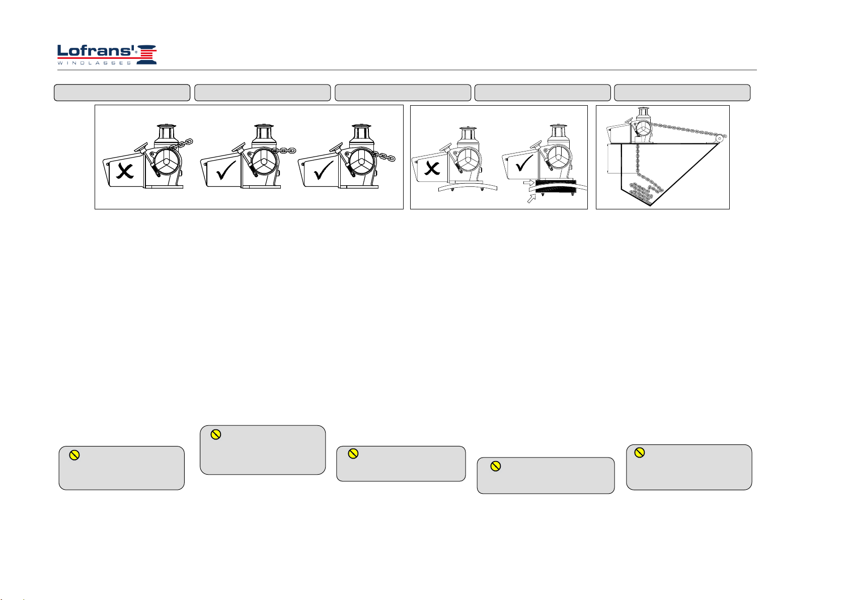
Le norme di sicurezza e gli enti
certificatori, richiedono tassativamente
che, durante lo stazionamento
all’ancora, il carico sia tenuto da un
ferma catena o da un punto di fissaggio
di elevata resistenza.
E’ responsabilità dell’utilizzatore
assicurarsi che durante la navigazione
l’ancora sia adeguatamente stivata e
fissata. Questa precauzione è tanto più
importante quanto maggiore è la
velocità di navigazione e peggiori siano
le condizioni del mare. Infatti un’ancora
filata per errore durante la navigazione
può avere effetti molto gravi. Data la
sua posizione e l’uso non sempre
frequente, il salpa ancore è
particolarmente esposto al rischio di
ossidazione e corrosione, pertanto è
necessario provvedere ad una costante
ispezione delle sue parti ed alla dovuta
manutenzione.
Assicurarsi di aver letto e compreso
ogni parte del presente manuale prima
di procedere con l’installazione e
l’utilizzo. Solo le persone che
conoscono come operare dovrebbero
essere autorizzate all’uso del salpa
ancore. In caso di dubbi circa
l’installazione o l’uso rivolgersi sempre
ad un consulente esperto.
• Salpa ancore utilizzati in modo
inappropriato possono causare danni a
persone e/o cose.
• Prestare la massima attenzione
durante l’uso di apparecchiature
potenti.
• Anche l’uso più accorto può essere
fonte di danni, anche gravi.
• I prodotti Lofrans vengono forniti
esclusivamente per l’uso nautico
diportistico. Lofrans declina ogni
responsabilità per usi impropri.
• Prestare la massima attenzione perchè
2 INFORMAZIONI DI SICUREZZA
Safety standards and certifying bodies
require peremptorily that, during the
standing of the anchor, the load must be
held by a chain stopper or a high
resistance fixing point.
The user is responsible for guaranteeing
that during navigation the anchor is
properly stowed and fixed. This
precaution is more important when the
navigation speed is higher and sea
conditions are worse. Indeed, an anchor
paid out by mistake during navigation
can have very serious effects.
Considering its position and not always
frequent use, the anchor windlass is
particularly exposed to oxidation and
corrosion risk; therefore, it is necessary
to arrange a constant inspection of its
parts and a due maintenance.
Make sure to have read and understood
every part of this manual before
proceeding with installation and use.
Only persons who know how to operate
should be authorised to use the anchor
windlass. Should there be doubts on its
installation or use, refer always to a
skilled consultant.
• Anchor windlasses used in an
inappropriate way can cause damages
to persons and/or things.
• Pay the utmost attention during the
use of powerful equipment.
• Even the most careful use can be a
source of damages, even serious.
• Lofrans products are supplied
exclusively for recreational nautical
use. Lofrans declines all responsibility
for improper uses.
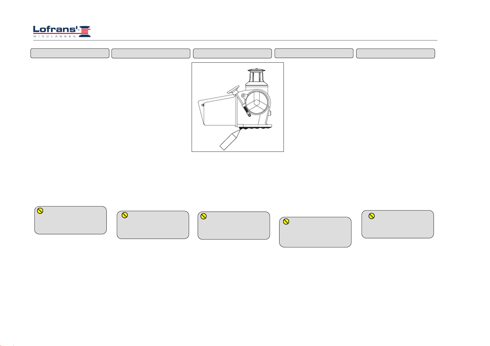
• Pay the utmost attention so that arms,
legs, fingers, hair, and clothes do not
get entangled in the chain or gipsy.
• Before operating the capstans, make
sure that there are no persons in water
in the vicinity.
• When the capstan is not used, the
2 INFORMATIONS SUR LA
SECURITE
Les normes de sécurité et les
organismes de certification exigent que,
durant le stationnement de l'ancre, la
charge soit retenue par un dispositif de
blocage de la chaîne ou par un point de
fixation à haut résistance.
L’utilisateur a la responsabilité de
garantir que l’ancre soit correctement
arrimée et fixée durant la navigation.
Cette précaution est d’autant plus
importante que la vitesse de navigation
est élevée et que les conditions de la
mer sont mauvaises. En effet, une ancre
qui file par inadvertance durant la
navigation est lourde de conséquences.
Etant donné sa position et son
utilisation pas toujours fréquente, le
guindeau est particulièrement exposé au
risque d’oxydation et de corrosion; il
est donc nécessaire de procéder à son
inspection constante et à son entretien.
Vérifier de bien avoir lu et compris le
manuel, dans toutes ses parties, avant
de procéder à l’installation et à
l’utilisation. Seules les personnes
sachant comment manœuvrer devraient
être autorisées à utiliser le guindeau. En
cas de doute sur l'installation ou sur
l'utilisation, toujours s’adresser à un
expert.
• Les guindeaux utilisés de façon
inappropriée peuvent provoquer des
dommages aux personnes et/ou aux
objets.
• Faire extrêmement attention lorsqu'on
utilise des appareillages puissants.
• Une utilisation très attentive peut
également être source de dommages,
voire graves.
• Les produits Lofrans sont
exclusivement fournis pour un usage
nautique de plaisance. Lofrans décline
toute responsabilité pour des usages
inappropriés.
2 SICHERHEITSINFORMATIONEN
Die Sicherheitsvorschriften und die
Zertifizierungs-Institute schreiben
ausdrücklich vor, dass während des
Ankerns die Last durch einen
Kettenstopper oder hochfesten
Befestigungspunkt gehalten wird.
Der Anwender trägt die Verantwortung,
dass der Anker während der Navigation
entsprechend verstaut und gesichert ist.
Diese Vorsichtsmaßnahme ist um so
wichtiger, je größer die
Navigationsgeschwindigkeit ist und je
schlechter Wetterbedingungen auf See
sind. Ein fälschlicherweise während
der Navigation abgefierter Anker kann
nämlich sehr schwere Auswirkungen
haben. Auf Grund ihrer Position und
der oftmals nicht häufigen Verwendung
ist die Ankerwinde besonders einer
Oxydations- und Korrosionsgefahr
ausgesetzt. Aus diesem Grund müssen
die Ankerwinden-Bauteile regelmäßig
kontrolliert und gewartet werden.
Vor der Installation und dem Einsatz
sicherstellen, dass das vorliegende
Handbuch in allen Teilen gelesen und
verstanden worden ist. Der Einsatz der
Ankerwinde darf nur Personen
genehmigt werden, die wissen, wie sie
zu bedienen ist. Bei Zweifeln bezüglich
der Installation und Bedienung, immer
an einen fachkundigen Berater wenden.
•Eine unsachgemäße Verwendung
von Ankerwinden kann Personen- und
Sachschäden verursachen.
•Beim Einsatz leistungsfähiger
Geräte sehr vorsichtig vorgehen.
•Auch ein sehr achtsamer Einsatz
kann Ursache von, auch schweren,
Schäden sein.
•Die Produkte des Unternehmens
Lofrans s.r.l. werden ausschließlich für
einen Einsatz im Rahmen von
nautischem Freizeitsport geliefert.
Lofrans s.r.l. haftet nicht für
2 INFORMAZIONI DI SICUREZZA
Las normas de seguridad y los entes de
certificación exigen que, durante el
fondeo con ancla, el esfuerzo se
descargue en un gancho/bloqueo para la
cadena o en un punto de fijación de
resistencia elevada.
Es responsabilidad del usuario controlar
que durante la navegación el ancla esté
estibada y sujetada adecuadamente.
Esta precaución es tanto más
importante cuanto mayor sea la
velocidad de navegación y peores las
condiciones del mar. De hecho, un
ancla filada por error durante la
navegación puede tener efectos muy
graves. Por su posición y por el uso a
veces poco frecuente, el molinete está
especialmente expuesto al riesgo de
oxidación y corrosión, por lo tanto es
necesario encargarse de una inspección
constante de sus partes y del debido
mantenimiento.
Asegúrese de haber leído y
comprendido cada parte del presente
manual antes de proceder con el
montaje y el uso. Deben ser autorizadas
a usar el molinete sólo las personas que
conocen el modo de hacerlo. En caso
de dudas sobre el montaje o el uso,
póngase siempre en contacto con un
consultor experto.
• Los molinetes utilizados en modo
inadecuado pueden causar daños a
personas y/u objetos.
• Ponga la máxima atención durante el
uso de aparatos potentes.
• Incluso el uso más prudente puede
causar daños, también graves.
• Los productos Lofrans se
proporcionan exclusivamente para el
uso náutico deportivo. Lofrans declina
toda responsabilidad en caso de
utilización impropia.
• Ponga la máxima atención, para que

Verricello Salpa Ancora mod. Titan
6
2 INFORMAZIONI DI SICUREZZA
braccia, gambe, dita, capelli e vestiti
non restino impigliati nella catena o nel
barbotin.
• Prima di manovrare con il verricello
assicurarsi che non ci siano persone in
acqua nelle vicinanze.
• Quando il verricello non viene
utilizzato l’ancora deve sempre essere
fissata ad un punto solido per evitare
danni.
• Il salpa ancore non deve mai essere
utilizzato come punto di ormeggio. Il
carico deve sempre essere tenuto da una
apposita bitta o punto solido.
•Il verricello non deve essere utilizzato
per funzioni differenti dal filare o
salpare l’ancora.
• Sulla campana di tonneggio non deve
essere mai utilizzata la catena.
• L’impianto deve sempre essere
protetto da un interruttore magneto
termico adeguato.
• Isolare sempre il circuito tramite
l’interruttore magneto termico quando il
salpa ancore non è in uso.
2 INFORMAZIONI DI SICUREZZA
anchor must always be fixed to a solid
point in order to avoid damages.
• The anchor windlass must never be
used as mooring point. The load must
always be held by a specific leat or
solid point.
• The capstan must not be used for
functions other than paying out or
weighing the anchor.
• The chain must never be used on the
warping drum.
• The system must always be protected
by a suitable circuit breaker.
• Disconnect always the circuit through
the circuit breaker when the anchor
windlass is not in use.
2 INFORMATION SUR LA
SECURITE
• Faire très attention à ce que Les bras,
les jambes, les doigts, les cheveux et les
vêtements ne s’entortillent pas dans la
chaîne ou le barbotin.
• Avant de manœuvrer le treuil du
guindeau, vérifier que personne ne se
trouve à proximité dan l’eau.
• Quand le treuil n’est pas utilisé,
l’ancre doit toujours être fixée à un
point solide pour éviter les
détériorations.
• Le guindeau ne doit jamais être utilisé
comme point d’amarrage. La charge
doit toujours être retenue par une bitte
ou un point solide.
• Le treuil ne doit pas être utilisé en-
dehors du fait de filer ou lever l’ancre.
• La chaîne ne doit jamais être utilisée
sur la cloche de touage.
• L’installation doit toujours être
protégée par un interrupteur
magnétothermique approprié.
• Toujours isoler le circuit au moyen de
l’interrupteur magnétothermique
lorsque le guindeau n’est pas utilisé.
2 SICHERHEITSINFORMATIONEN
unsachgemäße Verwendung.
•Sehr vorsichtig sein, damit sich
Arme, Beine, Finger, Haare und
Kleidungsstücke nicht in der Kette oder
der Kettennuss verhaken.
•Vor der Betätigung der Ankerwinde
sicherstellen, dass sich keine Personen
in der Nähe im Wasser aufhalten.
•Wenn die Ankerwinde nicht benutzt
wird, muss der Anker immer an einem
festen Punkt gesichert werden, um
Schäden zu vermeiden.
•Die Ankerwinde darf nie als
Vertaupunkt benutzt werden. Die Last
muss immer durch einen
entsprechenden Poller oder festen Punkt
gehalten werden.
•Die Ankerwinde darf nie zu einem
anderen Zweck als dem Abfieren oder
Lichten des Ankers verwendet werden.
•Am Verholspill darf nie die Kette
benutzt werden.
•Die Anlage muss immer durch einen
passenden, magnetthermischen
Motorschutzschalter abgesichert sein.
•Wird die Ankerwinde nicht genutzt,
muss der Stromkreis immer mit dem
magnetthermischen
Motorschutzschalter getrennt werden.
2 INFORMACIONES DE
SEGURIDAD
brazos, piernas, dedos, pelo y ropa no
queden atrapados en la cadena o en el
barbotén.
• Antes de maniobrar con el cabestrante
asegúrese que no haya nadie en el agua
en los alrededores.
• Cuando no se utiliza el cabestrante, el
ancla siempre tiene que estar sujetada a
un punto sólido para evitar daños.
• El molinete nunca debe ser utilizado
como punto de amarre. El esfuerzo
siempre lo debe soportar un amarradero
apropiado o un punto sólido.
• El cabestrante no debe ser utilizado
para funciones diferentes de filar o
levar el ancla.
• Nunca se debe utilizar la cadena
encima del virador de atoaje.
• La instalación tiene que estar
protegida por un interruptor magneto-
térmico adecuado.
• Aislar siempre el circuito mediante el
interruptor magneto-térmico cuando el
molinete no se usa.

Verricello Salpa Ancora mod. Titan
7
3 INSTALLAZIONE
3.1 Contenuto della confezione
Oltre al presente manuale, la confezione
contiene:
- salpa ancora completo di
motoriduttore
- Cassetta teleruttori/teleinvertitori
- Dima di foratura
- Leva
- Viteria
3.2 Attrezzature necessarie per
l'installazione
- Trapano
- Punta da 10 mm per legno e acciaio
- Chiavi esagonali da 10 mm, 13 mm e
17 mm
3.3 Accessori consigliati
Utilizzare esclusivamente accessori e
ricambi originali Lofrans, progettati e
costruiti in modo da assicurare
prestazioni, durata e mantenere valida
la garanzia. Per informazioni sui
ricambi disponibili, rivolgersi al
rivenditore locale o visitare il sito
www.lofrans.com
3 INSTALLATION
3.1 Contents of the package
In addition to the present manual, the
package contains:
- Anchor windlass complete with motor
reducer
- Remote control switch/remote control
reverser box
- Drilling template
- Handle
- Screws
3.2 Equipment necessary for
installation
- Drill
- 10 mm bit for wood and steel
- 10 mm., 13 mm., and 17 mm. hexagon
keys
3.3 Recommended accessories
Use exclusively original Lofrans
accessories and spare parts, designed
and manufactured to ensure
performances, duration and for keeping
valid the warranty. For information on
available spare parts, contact your local
reseller or visit website
www.lofrans.com
3 INSTALLATION
3.1 Contenu de l’emballage
Outre ce manuel, l’emballage contient:
- un guindeau avec son motoréducteur
- Un boitier de télérupteurs/télé-
inverseurs
- Gabarit de perçage
- Levier
- Visserie
3.2 Outillage nécessaire à
l’installation
- Perceuse
- Foret de 10 mm pour bois et acier
- Clés à six pans de 10 mm, 13 mm et
17 mm
3.3 Accessoires conseillés
Utiliser exclusivement les accessoires et
les pièces détachées originales Lofrans,
conçues et fabriquées de façon à
garantir les performances, la longévité
et la validité de la garantie. Pour de plus
amples informations sur les pièces
détachées disponibles, s’adresser au
revendeur local ou visiter le site
www.lofrans.com
3 INSTALLATION
3.1Packungs-Inhalt
Die Packung enthält, außer dem
vorliegenden Handbuch, folgendes:
- Ankerwinde komplett mit
Getriebemotor
- Kasten Fernrelais/ Fernumschalter
- Bohrschablone
- Hebel
- Schraubensatz
3.2 Für die Installation benötigte
Werkzeuge
- Bohrer
- 10mm-Bohrspitze für Holz und Metall
- Sechskantschlüssel mit 10 mm, 13
mm und 17 mm
3.3 Empfohlenes Zubehör
Ausschließlich Original-Zubehör und
Ersatzteile des Unternehmens Lofrans
s.r.l. verwenden, das so entwickelt und
hergestellt wurde, dass Leistung,
Haltbarkeit und Gültigkeit der Garantie
sichergestellt werden. Für
Informationen zu erhältlichen
Ersatzteilen, wenden Sie sich bitte an
den örtlichen Händler oder besuchen
Sie die Internetseite www.lofrans.com..
3 MONTAJE
3.1 Contenido del embalaje
Además del presente manual, el
embalaje contiene:
- molinete equipado con motor reductor
- Caja telerruptores/teleinversores
- Plantilla de perforación
- Palanca
- Tornillería
3.2 Herramientas necesarias para el
montaje
- Taladradora
- Broca de 10 mm para madera y acero
- Llaves hexagonales de 10 mm, 13 mm
y 17 mm
3.3 Accesorios aconsejados
Utilice exclusivamente los accesorios y
repuestos originales Lofrans,
proyectados y construidos para asegurar
prestaciones y duración, además de
mantener la validez de la garantía. Para
informaciones sobre los repuestos
disponibles, contacte con el vendedor
local o visite la página web
www.lofrans.com.

Verricello Salpa Ancora mod. Titan
8
3 INSTALLAZIONE 3 INSTALLATION 3 INSTALLATION 3 INSTALLATION 3 MONTAJE
30
3.4 Requisiti generali per
l’installazione
Per il corretto funzionamento del salpa
ancore, esso deve essere installato in
modo da soddisfare le seguenti
condizioni:
1 –Altezza puntale: deve essere tale
da garantire un’inclinazione della
catena inferiore ai 90 gradi.
2 - Deve essere garantito il
parallelismo tra i piani di coperta; se
ciò non dovesse accadere compensare
opportunamente la differenza.
3 - Profondità gavone: la caduta della
catena nel gavone deve essere tale per
cui, a catena completamente salpata,
occorre avere un minimo di 300 mm tra
la parte inferiore del ponte e la cima del
mucchio di catena raccolta.
Il mancato rispetto di
questi requisiti provocherà il
non corretto funzionamento del
salpa ancore.
3.4 General requirements for
installation
In order to operate the anchor windlass
correctly, it must be installed to meet
the following conditions:
1 –Bow roller height: it must be such
to guarantee a chain inclination lower
than 90 degrees.
2 –The parallelism between deck
floors must be guaranteed; should it not
occur, duly compensate the difference.
3 –Chain locker depth: the chain fall
into the chain locker must be such that
when the chain is completely stored,
there must be a minimum of 300 mm.
between the underside of the deck and
the top of the heaped chain.
Non-observance of these
requirements will cause the
malfunctioning of the anchor
windlass.
3.4 Conditions générales requises pour
l’installation
Pour que le guindeau fonctionne
correctement, celui-ci doit être installé
de façon à remplir les conditions
suivantes:
1 –Hauteur du gaillard: il doit
pouvoir garantir une inclinaison de la
chaîne inférieure à 90 degrés.
2 –Le parallélisme entre les plans du
plancher doit être garanti; si ce n’est
pas le cas, compenser la différence de
façon opportune.
3 –Profondeur du coffre : une fois la
chaîne complètement levée et sa chute
dans le coffre, on doit avoir un
minimum de 300 mm entre la partie
inférieure du pont et le sommet de
l’amas de la chaîne.
Si ces conditions ne sont pas
remplies le guindeau ne pourra
fonctionner correctement.
3.4 Allgemeine Voraussetzungen für
die Installation
Für den richtigen Betrieb der
Ankerwinde muss die Ankerwinde so
installiert werden, dass folgende
Voraussetzungen erfüllt sind:
1 - Höhe der Deckstütze: Sie muss so
sein, dass eine Neigung der Kette von
weniger als 90 Grad garantiert ist.
2 - Zwischen den Deckebenen muss
eine Parallelstellung garantiert werden.
Ist dies nicht der Fall, muss der
Unterschied auf geeignete Weise
ausgeglichen werden.
3 - Tiefe des Kettenkastens: Das
Ablassen der Kette in den Kettenkasten
muss so sein, dass bei vollständig
gelichteter Kette ein Mindestabstand
von 300 mm zwischen der Deck
Unterseite und dem obersten Teil des
eingesammelten Kettenhaufens gegeben
ist.
Die Nichtbeachtung dieser
Voraussetzungen führt zu einem
falschen Betrieb der Ankerwinde.
3.4 Requisitos generales para el
montaje
Para el correcto funcionamiento del
molinete, hay que instalarlo de forma
que estén satisfechas las condiciones
siguientes:
1 –Altura de la roda: debe garantizar
una inclinación de la cadena inferior a
los 90 grados.
2 - Debe estar garantizado el
paralelismo entre los planos de
cubierta; si no fuera así, compense
oportunamente la diferencia.
3 - Profundidad del pozo del ancla: la
caída de la cadena en el pozo debe ser
tal que, con el ancla completamente
levada, quede un mínimo de 300 mm
entre la parte inferior del puente y la
parte superior de la pila de cadena
recogida.
El no respeto a estos
requisitos provoca el
funcionamiento incorrecto del
molinete.
1
2
3

Verricello Salpa Ancora mod. Titan
9
3 INSTALLAZIONE 3 INSTALLATION 3 INSTALLATION 3 INSTALLATION 3 MONTAJE
3.5 Prevenzione dall'elettrolisi
Per imbarcazioni in alluminio è
essenziale che il salpa ancore sia isolato
dal ponte tramite una guarnizione non
conduttiva (non fornita). Inoltre è
importante che anche ancora e catena
siano isolate dallo scafo, inclusi chain
locker e sistemi di fissaggio.
Senza queste precauzioni il
fenomeno dell’elettrolisi porterà
a una rapida corrosione del
salpa ancore.
3.5 Prevention from electrolysis
For aluminium boats, it is essential that
the anchor windlass be insulated from
the deck through a non-conductive
gasket (not supplied). In addition, it is
important that also the anchor and the
chain be insulated from the hull,
including chain locket and fixing
systems.
Without these precautions,
the electrolysis phenomenon will
lead to a rapid corrosion of the
anchor windlass.
3.5 Pévention contre l’électrolyse
Pour les embarcations en aluminium, il
est fondamental que le guindeau soit
isolé du pont par une garniture non
conductrice (non fournie). Il est
également important d’isoler l’ancre et
la chaîne de la coque, y compris le
dispositif d’arrêt de la chaîne et les
systèmes de fixation.
Si ces précautions ne sont
pas prises, le phénomène de
l’électrolyse entrainera une
corrosion rapide du guindeau.
3.5 Elektrolyse-Verhütung
Für Boote in Aluminiumbauweise ist es
von wesentlicher Bedeutung, dass die
Ankerwinde mit einer nicht leitenden
Dichtung (gehört nicht zum
Lieferumfang) von Deck isoliert ist.
Außerdem ist es wichtig, dass auch der
Anker und die Kette, einschließlich
Kettenkasten und Befestigungssysteme,
vom Schiffsrumpf isoliert sind.
Ohne diese
Vorsichtsmaßnahmen führen
Elektrolyse-Erscheinungen zu
einer schnellen Korrosion der
Ankerwinde..
3.5 Prevención de la electrólisis
Para los barcos en aluminio es esencial
que el molinete esté aislado del puente
por medio de una junta no conductiva
(no presente en el paquete). Es
importante, además, que también el
ancla y la cadena estén aisladas del
casco, incluidos chain locker y sistemas
de sujeción
Sin estas precauciones el
fenómeno de la electrólisis
provocará una rápida corrosión
del molinete.

Verricello Salpa Ancora mod. Titan
10
3 INSTALLAZIONE 3 INSTALLATION 3 INSTALLATION 3 INSTALLATION 3 MONTAJE
3.6 Installazione in coperta
1 - Posizionare con cura la dima di
foratura sul ponte, assicurandosi del
corretto allineamento con la prua.
2 - Marchiare e forare come indicato in
figura. Lasciare vivi gli spigoli dei fori,
mentre la parte del bordo del foro
catena in direzione della prua deve
essere lisciato per un angolo di 45°.
3 - Posizionare con cura la parte
superiore del salpa ancora sulla coperta.
4 - Posizionare con cura il bicchiere
staccacatena in modo che lo
staccacatena sia allineato e distante 4-5
mm dalla gola del barbotin
5 –Collegare i cavi provenienti dalla
batteria al motore elettrico facendoli
passare per le aperture presenti sul
corpo riduttore.
Nota:
E’ consigliato sigillare la base del salpa
ancora alla coperta tramite colla
siliconica.
3.6 Deck installation
1 –Place carefully the drilling template
on the deck, by ensuring the correct
alignment with the bow.
2 - Mark and drill as indicated in the
figure. Let the edges of the holes sharp,
while the edge side of the holes of the
chain towards the bow must be
smoothed for an angle of 45° degree.
3 - Place carefully the upper part of the
anchor windlass on the deck.
4 - Carefully place the chain stripper
pipe so that the chain stripper is aligned
and away 4-5 mm from the gipsy throat.
5- Connect the wires from the battery
to the electrical engine by passing them
out through the openings in the gearbox
body.
Note:
It is recommended to seal the base of
the anchor windlass to the deck by
means of silicone glue.
3.6 Installation sur le pont
1 -Positionner soigneusement le gabarit
de perçage sur le pont, en s’assurant
qu’il est bien dans l’axe de la proue.
2 –Marquer puis percer comme indiqué
sur la figure. Laisser des arêtes vives
dans les trous mais lisser la partie du
bord de la chaîne, en direction de la
proue, sur un angle de 45 °.
3 –Positionner soigneusement la partie
supérieure du guindeau sur le plancher.
4 –Positionner soigneusement le godet
stoppeur de chaîne de façon à ce que ce
dernier soit aligné sur la gorge du
barbotin, à 4-5 mm de distance.
5 –Brancher les câbles de la batterie sur
le moteur électrique, en les faisant
passer par les ouvertures prévues sur le
corps du réducteur.
Remarque:
Il est conseillé de sceller la base du
guindeau sur le plancher avec du
silicone.
3.6 Auf Deck Installation
1- Die Bohrschablone sorgfältig auf
dem Deck positionieren. Sicherstellen,
dass sie richtig auf den Bug
ausgerichtet ist.
2- Wie in der Abbildung gezeigt
markieren und bohren. Die Kanten der
Bohrungen scharf lassen. Die Kante des
Kettenlochs in Richtung Bug muss
hingegen im 45°-Winkel geglättet
werden.
3 -Das Oberteil der Ankerwinde
sorgfältig auf dem Deck positionieren.
4 -Den Becher des Kettenabstreifers so
positionieren, dass der Kettenabstreifer
ausgerichtet ist und sich in einem
Abstand von 4-5 mm von der Rille an
der Kettennuss befindet.
5 –Die von der Batterie kommenden
Kabel an Elektromotor anschließen. Die
Kabel müssen durch die Öffnungen am
Gehäuse des Untersetzungsgetriebes
eingezogen werden.
Anmerkung:
Der Sockel der Ankerwinde sollte auf
dem Deck mit Silikonkleber abgedichtet
werden.
3. Montaje en cubierta
1 - Coloque con cuidado la plantilla de
perforación en el puente, asegurándose
de la alineación correcta con la roda de
proa.
2 - Marque y perfore como indicado en
la figura. Deje vivas las aristas de los
orificios, mientras que la parte del borde
del orificio de la cadena en dirección de
la proa debe ser lijada con un ángulo de
45°.
3 - Coloque con cuidado la parte
superior del molinete en la cubierta.
4 - Colocar con cuidado el vaso del
dispositivo de desenganche de la cadena
de forma che el dispositivo esté
alineado y a una distancia de 4-5 mm de
la garganta del barbotén
5 –Conectar los cables provenientes de
la batería al motor eléctrico haciéndolos
pasar por las aperturas presentes en el
cuerpo reductor.
Nota:
Se aconseja sellar la base del molinete a
la cubierta con cola silicónica.
1
2
3
4
5

Verricello Salpa Ancora mod. Titan
11
4 IMPIANTO ELETTRICO 4 ELECTRICAL SYSTEM 4 SECTION CABLES ELETRIQUES 4 ELEKTRISCHE ANLAGE 4 SISTEMA ELECTRICO
Model
Motor
Power
(W)
Voltage
(V)
Contactor (A)
Cable sizing according lengh of cable (positive + negative)
15-25 m
50-75 ft
> 25 m
> 75 ft
Titan
2000
24
100
50 mm2
1 AWG
90 mm2
000 AWG
4.1 Sezione dei cavi elettrici
Per ottenere le massime prestazioni dal
salpa ancora e salvaguardare l'impianto
elettrico, è essenziale che il salpa
ancora sia cablato con cavi di
sufficiente sezione come suggerito in
tabella.
4.2 Solenoidi (Control Box)
Collocare in un luogo asciutto vicino al
verricello.
4.3 Circuit breaker
I circuit breaker consigliati da Lofrans
hanno una curva di intervento e non un
semplice valore di targa. Gli interruttori
selezionati per ogni modello
garantiscono il corretto funzionamento
del sistema.
4.4 Pannello di controllo remoto
Il pannello di controllo remoto deve
essere montato in una posizione
comoda (come ponte, timone o
pozzetto), in modo che l'operatore
possa vedere il verricello durante la
manovra. Montare e sigillare il
pannello in modo che i terminali
risultino in un luogo asciutto.
4.1 Electrical cable section
In order to obtain the maximum
performances from the anchor
windlass and safeguard the electrical
system, it is essential that the anchor
windlass be wired with cables of
sufficient section as suggested in the
table.
4.2 Solenoid valves (Control Box)
Place it in a dry place near the capstan.
4.3 Circuit breakers
The circuit breakers recommended by
Lofrans have an intervention curve
and not a simple plate value. The
switches selected for each model
guarantee the correct operation of the
system.
4.4 Remote control electric panel
board
The remote control electric panel
board must be mounted in a
comfortable position (such as the
deck, the rudder or the cockpit), so
that the operator can see the capstan
during the manoeuvre. Mount and seal
the electric panel board so that the
terminals remain in a dry place.
4.1 Section des câbles électriques
Pour obtenir le meilleur rendement du
guindeau et préserver le circuit électrique
il est essentiel que le guindeau soit câblé
avec des câbles d’une section suffisante,
comme montré dans le tableau.
4.2 Solénoïdes (Control Box)
Placer dans un endroit sec, près du treuil.
4.3 Disjoncteur
Les disjoncteurs conseillés par Lofrans
ont une courbe d’intervention et pas une
simple valeur d’étiquette. Les
interrupteurs sélectionnés pour chaque
modèle garantissent le bon
fonctionnement du système.
4.4 Panneau de commande à distance
Le panneau de commande à distance doit
être monté dans un endroit pratique (le
pont, le gouvernail ou le cockpit), de
façon à ce que l’opérateur puisse voir le
treuil durant la manœuvre. Monter et
sceller le panneau de sorte que les
extrémités des câbles se trouvent en lieu
sec.
4.1 Querschnitt der Stromkabel
Um maximale Leistungswerte von der
Ankerwinde zu erhalten und die
elektrische Anlage zu schützen, ist es
von grundlegender Bedeutung, dass die
Ankerwinde mit Kabeln mit
ausreichendem Querschnitt (siehe
Angaben in der Tabelle) verkabelt wird.
4.2 Relaisbox (Control-Box)
An einem trockenen Ort in der Nähe der
Ankerwinde anbringen.
4.3 Sicherungsautomat
Die vom Unternehmen Lofrans
empfohlenen Sicherungsautomaten
haben eine Auslösekurve und keinen
einfachen Typenschild-Wert. Die für
jedes Modell ausgewählten Schalter
garantieren den richtigen Betrieb der
Anlage.
4.4 Fernbedienungs-Schalttafel
Die Fernbedienungs-Schalttafel muss
einer bequemen Position (wie Brücke,
Ruder oder Cockpit) montiert werden, so
dass der Bediener die Ankerwinde
während des Manövers sehen kann. Die
Fernbedienungs-Schalttafel so montieren
und abdichten, dass sich die Anschlüsse
an einem trockenen Ort befinden.
4.1 Sección de los cables eléctricos
Para obtener las máximas prestaciones
del molinete y proteger la instalación
eléctrica, es esencial que el molinete
esté cableado con cables de sección
suficiente, como se sugiere en la tabla.
4.2 Solenoides (Control Box)
Coloque en un lugar seco cerca del
cabestrante.
4.3 Circuit breaker
Los "circuit breaker" aconsejados por
Lofrans tienen una curva de
intervención, en vez de un simple
valor nominal. Los interruptores
seleccionados para cada modelo
aseguran el funcionamiento correcto
del sistema.
4.4 Panel de mandos a distancia
El panel de mandos a distancia se
debe montar en una posición cómoda
(como el puente, el timón o el pozo),
para que el operador pueda ver el
cabestrante durante la maniobra.
Monte y selle el panel de modo que
los bornes estén en un lugar seco.

Verricello Salpa Ancora mod. Titan
12
4 IMPIANTO ELETTRICO 4 ELECTRICAL SYSTEM 4 INSTALLATION ELECTRIQUE 4 ELEKTRISCHE ANLAGE 4 EQUIPO ELÉCTRICO
4.5 Schema di collegamento
4.5 Wiring Diagram
4.5 Schema de cablage
4.5 Schaltplan
4.5 Diagrama de cableado

Verricello Salpa Ancora mod. Titan
13
4 IMPIANTO ELETTRICO 4 ELECTRICAL SYSTEM 4 INSTALLATION ELECTRIQUE 4 ELEKTRISCHE ANLAGE 4 EQUIPO ELÉCTRICO
4.5 Schema di collegamento
4.5 Wiring Diagram
4.5 Schema de cablage
4.5 Schaltplan
4.5 Diagrama de cableado

Verricello Salpa Ancora mod. Titan
14
4 IMPIANTO ELETTRICO 4 ELECTRICAL SYSTEM 4 INSTALLATION ELECTRIQUE 4 ELEKTRISCHE ANLAGE 4 EQUIPO ELÉCTRICO
4.5 Schema di collegamento
4.5 Wiring Diagram
4.5 Schema de cablage
4.5 Schaltplan
4.5 Diagrama de cableado

Verricello Salpa Ancora mod. Titan
15
5 USO DEL SALPA ANCORA 5 USE OF THE WINDLASS 5 UTILISATION DU GUINDEAU 5 BEDIENUNG DER ANKERWINDE 5 USO DEL MOLINETE
Durante l'uso del salpa ancora,
non passare direttamente da una
direzione all'altra ma aspettare
che il salpa ancora si fermi prima
di dare il comando nella direzione
opposta.
5.1 Calare l'ancora
La calata dell'ancora si può effettuare
tramite comando elettrico o a gravità:
5.1.1 Calare l'ancora elettricamente
1 –Assicurarsi che la frizione sia
serrata e che il freno sia aperto. Aprire
tutti i dispositivi di fissaggio catena.
2 –Armare l’interruttore di sicurezza
3 - Premere il pulsante DOWN dal
comando a vostra disposizione. In
questo modo la calata della catena sarà
perfettamente controllabile e lo
svolgimento della catena regolare.
4 - Una volta calata la catena disarmare
l'interruttore di sicurezza.
5 - Chiudere i dispositivi di fissaggio
catena.
During the use of the anchor
windlass, do not change directly
from one direction to the other
but wait until the anchor windlass
stops before manipulating the
control into the opposite direction
5.1 Lowering the anchor
Lowering of the anchor can be carried
out through the electric control or by
gravity:
5.1.1 Lowering the anchor electrically
1 –Make sure that the clutch is
tightened and the brake is disengaged.
Disengage all chain fixing devices.
2 –Activate the safety switch
3 –Press the DOWN button from the
control at your disposal. In this way, the
lowering of the chain will be perfectly
controllable and the unwinding of the
chain regular.
4 –Once the chain is lowered,
deactivate the safety switch.
5 –Engage the chain fixing devices.
Lorsqu’on utilise le guindeau,
ne pas passer directement d’une
direction à l’autre mais attendre
que le guindeau s’arrête. Ensuite,
on peut commander la direction
inverse.
5.1 Jeter l’ancre
L’ancre peut être jetée depuis une
commande électrique ou par gravité:
5.1.1 Jeter l'ancre électriquement
1 –Vérifier que l’embrayage soit serré
et le frein ouvert. Libérer tous les
dispositifs de fixation de la chaîne.
2 –Armer l’interupteur de sécurité
3 –Appuyer sur le bouton DOWN sur
la commande à disposition. De cette
façon, on pourra parfaitement contrôler
l’opération et la chaîne se déroulera de
façon régulière.
4 –Une fois que la chaîne est
descendue, désarmer l’interrupteur de
sécurité.
5 –Refermer les dispositifs de fixation
de la chaîne.
Bei der Bedienung der
Ankerwinde niemals von einer
Richtung direkt auf die andere
umschalten, sondern abwarten,
dass die Ankerwinde anhält,
bevor der Steuerbefehl für die
andere Richtung gegeben wird.
5.1 Den Anker fallen lassen
Der Anker kann elektrisch oder durch
Schwerkraft fallen gelassen werden.
5.1.1 Den Anker elektrisch fallen
lassen
1 - Sicherstellen, dass die Kupplung
gezogen und die Bremse geöffnet ist.
Alle Ketten-Sperrvorrichtungen öffnen.
2 - Den Schutzschalter einschalten.
3 - Die Taste DOWN an der Ihnen
zur Verfügung stehenden Steuerung
drücken. Auf diese Weise kann das
Ablassen und das regelmäßige
Abwickeln der Kette perfekt kontrolliert
ùwerden.
4 - Ist die Kette abgelassen worden,
ùden Schutzschalter ausschalten.
5 - Die Ketten-Sperrvorrichtungen
schließen.
Durante el uso del molinete, no
pase directamente de una
dirección a otra sino espere que el
molinete se pare antes de
arrancar en la dirección
contraria.
5.1 Echar el ancla
Se puede echar el ancla por medio de un
mando eléctrico o por gravedad:
5.1.1 Echar el ancla eléctricamente
1 –Asegúrese de que el embrague esté
apretado y que el freno esté abierto.
Abra todos los dispositivos de sujeción
de la cadena.
2 –Arme el interruptor de seguridad.
3 - Presione el botón DOWN del mando
a su disposición. De esta manera, la
bajada de la cadena será perfectamente
controlable y el desenrollado será
regular.
4 - Una vez echada la cadena desarme
el interruptor de seguridad.
5 - Active los dispositivos de sujeción
de la cadena.
LOCK
UNLOCK

Verricello Salpa Ancora mod. Titan
16
5 USO DEL SALPA ANCORA 5 USE OF THE WINDLASS 5 UTILISATION DU GUINDEAU 5 BEDIENUNG DER ANKERWINDE 5 USO DEL MOLINETE
.Assicurarsi che il salpa
ancora non sia alimentato prima
di effettuare interventi manuali
5.1.2 Calare l'ancora a gravità
1 –Assicurarsi che la frizione sia
serrata e poi aprire chain stopper o
fermi di sicurezza. Aprire il freno.
2 - Aprire la gradualmente frizione per
mezzo della leva di manovra..
Nota: per regolare la velocità di discesa
della catena agire, per mezzo della leva,
sulla frizione. Ruotandola in senso
orario si aumenterà la frenatura della
catena (fino al completo arresto),
mentre in senso anti-orario si ridurrà la
frenatura.
3 - Fissare la catena (o la cima) ad una
presa di forza.
Aprendo completamente la
frizione l'ancora verrà calata con
estrema velocità. Di conseguenza,
il rapido passaggio della catena
nella cuffia e nel puntale potrebbe
danneggiarli. Si consiglia di
controllare sempre la velocità in
di calata dell’ancora.
.Make sure the anchor windlass
is not powered before carrying
out manual interventions.
5.1.2 Lowering the anchor by gravity
1 –Make sure that the clutch is
tightened and then disengage the chain
stopper or safety stops. Disengage the
brake.
2 –Disengage the clutch gradually
through the manoeuvre handle.
Note: to adjust the descent speed of the
chain act, through the handle, on the
clutch. By turning it clockwise, the
braking speed of the chain will increase
(until complete stop), while by turning
it anticlockwise, braking will be
reduced.
3 –Fix the chain (or the rope) to a
strong point.
By disengaging completely the
clutch, the anchor will be lowered
at high speed. Consequently, the
fast passage of the chain into the
hood and bow roller could
damage them. It is recommended
always to check the speed.
.Vérifier que l’alimentation du
guindeau est coupée avant de
procéder aux interventions
manuelles.
5.1.2 Jeter l’ancre par gravité
1 –Vérifier que l’embrayage est serré
puis ouvrir le stoppeur de chaîne ou les
blocages de sécurité. Ouvrir le frein.
2 –Ouvrir progressivement
l’embrayage au moyen du levier.
Remarque: pour régler la vitesse de
descente de la chaîne, agir sur
l’embrayage au moyen du levier. Si on
le tourne dans le sens des aiguilles
d’une montre, on augmente le freinage
de la chaîne (jusqu’à son arrêt complet).
En revanche, dans le sens inverse, on
réduit l’effet de freinage.
3 –Fixer la chaîne (ou le cordage) à une
prise de mouvement
Si on ouvre complètement
l’embrayage, l’ancre sera jetée à très
grande vitesse. Par conséquent, le
passage rapide de la chaîne dans le
couvercle et dans le gaillard pourrait
provoquer une détérioration. Il est
conseillé de toujours contrôler la
vitesse.
.Vor eventuellen manuellen
Eingriffen sicherstellen, dass die
Ankerwinde nicht mit Strom
versorgt ist.
5.1.2 Den Anker durch Schwerkraft
fallen lassen
1- Sicherstellen, dass die Kupplung
gezogen ist und dann den Kettenstopper
oder die Sperrvorrichtungen öffnen. Die
Brems öffnen.
2 - Die Kupplung nach und nach mit
Hilfe des Bedienhebels öffnen.
Anmerkung: Die Regulierung der Ablass-
Geschwindigkeit der Kette erfolgt über
den Hebel an der Kupplung. Wird er in
Uhrzeigersinn gedreht, wird die Kette
stärker gebremst (bis zum kompletten
Halt). Bei Drehen gegen den
Uhrzeigersinn wird die Bremskraft
verringert.
3 - Die Kette (oder das Tau) an einer
Zugkraft-Befestigung befestigen.
. Wird die Kupplung vollständig
geöffnet, wird der Anker extrem schnell
fallen gelassen. Durch die schnelle
Durchführung der Kette durch die
Haube und die Deckstütze können diese
Bauteile beschädigt werden. Es wird
empfohlen, die Geschwindigkeit immer
zu kontrollieren.
.Asegúrese de que el molinete
no esté alimentado antes de
efectuar intervenciones manuales.
5.1.2 Echar el ancla por gravedad
1 –Asegúrese de que el embrague esté
cerrado, luego abra el estopor (chain
stopper) o los cierres de seguridad. Abra
el freno.
2 - Abra gradualmente el embrague
mediante la palanca de maniobra.
Nota: para ajustar la velocidad de
descenso de la cadena actuar sobre el
embrague con la palanca. Girándola en
el sentido de las agujas del reloj se
aumenta el frenado de la cadena (hasta
la parada completa), mientras que en
sentido contrario a las agujas del reloj
se reduce el frenado.
3 - Sujete la cadena (o el cabo) a un
punto sólido.
Al abrir completamente el
embrague, el ancla bajará con
velocidad muy alta. Por lo tanto,
el pasaje rápido de la cadena en el
cárter y en la roda podría
perjudicarlos. Se aconseja
controlar siempre la velocidad.

Verricello Salpa Ancora mod. Titan
17
5 USO DEL SALPA ANCORA 5 USE OF THE WINDLASS 5 UTILISATION DU GUINDEAU 5 BEDIENUNG DER ANKERWINDE 5 USO DEL MOLINETE
5.2 Salpare l'ancora
1 - Accertarsi che l'interruttore magneto
idraulico o magneto elettrico sia armato.
2 - Assicurarsi che la frizione sia ben
serrata e il freno aperto. Estrarre la
leva di manovra dalla campana o dal
barbotin.
3 –Aprire chain stoppe e fermi di
sicurezza
4 - Premere il pulsante UP dal comando
a vostra disposizione fino a quando
l'ancora avrà acquistato la sua posizione
all'interno del puntale.
5 - Disarmare l'interruttore magneto
idraulico o magneto elettrico.
6 - Fissare la catena con il ferma catena.
In questo modo si eviterà un potenziale
danneggiamento del salpa ancora e si
eviteranno inattesi rilasci della catena.
Non eseguire l'operazione di
recupero della ancora affidandosi
solo alle batterie di bordo.
Accendere il motore
dell'imbarcazione (o il generatore)
per ottenere la forza elettro
motrice necessaria.
5.2 Weighing the anchor
1 –Make sure that the hydraulic
magnetic circuit breaker is activated.
2 - Make sure that the clutch is well
tightened and the brake is disengaged.
Take out the manoeuvre handle from
the drum or gipsy.
3 –Disengage the chain stopper and
safety stops.
4 –Press the UP button from the control
at your disposal until the anchor reaches
its position inside the bow roller.
5 –Deactivate the hydraulic magnetic
circuit breaker.
6 –Fix the chain with the chain stopper.
In this way a potential damage of the
anchor windlass will be avoided as well
as unexpected chain releases.
Do not carry out the anchor
recovery operation by relying only
on the onboard batteries. Start the
motor of the boat (or the
generator) to obtain the necessary
electromotive force.
5.2 Lever l’ancre
1 –Vérifier que l’interrupteur magnéto-
hydraulique est armé.
2 –Vérifier que l’embrayage est bien
serré et le frein ouvert. Extraire le
levier de manœuvre de la poupée ou
du barbotin.
3 –Ouvrir le stoppeur de chaîne et les
blocages de sécurité.
4 –Appuyer sur le bouton UP sur la
commande à votre disposition jusqu’à
ce que l’ancre ait pris position à
l’intérieur du gaillard.
5 –Désarmer l’interrupteur magnéto-
hydraulique ou magnéto-électrique.
6 –Fixer la chaîne avec le dispositif
d’arrêt. On évitera ainsi une
détérioration potentielle du guindeau et
des relâchements impromptus de la
chaîne.
Eviter autant de récupérer
l’ancre en n’utilisant que les
batteries du bord. Allumer le
moteur de l’embarcation (ou le
générateur) pour obtenir la force
motrice électrique nécessaire.
5.2 Den Anker lichten
1 - Sicherstellen, dass der magnet
Hydraulische bzw. magnet-elektrische
Schalter eingeschaltet ist.
2 - Sicherstellen, dass die Kupplung gut
angezogen und die Bremse geöffnet st.
Den Bedienhebel aus dem Verholspill
oder der Kettennuss herausziehen.
3 - Den Kettenstopper und die
Sperrvorrichtungen öffnen.
4 - Die Taste UP an der Ihnen zur
Verfügung stehenden Steuerung solange
drücken, bis der Anker seine Position in
der Deckstütze eingenommen hat.
5 - Den magnet-hydraulischen bzw.
Magnet elektrischen Schalter
ausschalten.
6 - Die Kette mit dem Kettenstopper
sichern. Auf diese Weise wird eine
mögliche Beschädigung der
Ankerwinde und ein versehentliches
Lösen der Kette vermieden.
Verlassen Sie sich beim
Einholen des Ankers nicht nur auf
die Bordbatterien. Den Bootsmotor
(oder den Generator) einschalten,
um die nötige elektromotorische
Kraft zuerhalten.
5.2 Levar el ancla
1 - Asegúrese de que el interruptor
magneto-hidráulico o magneto-eléctrico
esté armado.
2 - Controle que el embrague esté bien
cerrado y el freno abierto. Extraiga la
palanca de maniobra de la campana o
del barbotén.
3 –Abra el estopor (chain stopper) y los
cierres de seguridad.
4 - Presione el botón UP del mando a su
disposición hasta que el ancla llegue a
su posición al interior de la roda.
5 - Desarme el interruptor magneto-
hidráulico o magneto-eléctrico.
6 - Fije la cadena con el estopor (chain
stopper). De esta forma se evitará un
daño potencial del molinete y se evitará
que la cadena pueda desenrollarse
inesperadamente.
No efectúe la operación de
recuperación del ancla confiándola
sólo a las baterías de a bordo.
Encienda el motor del barco (o el
generador) para obtener la fuerza
electromotriz necesaria.

Verricello Salpa Ancora mod. Titan
18
5 USO DEL SALPA ANCORA 5 USE OF THE WINDLASS 5 UTILISATION DU GUINDEAU 5 BEDIENUNG DER ANKERWINDE 5 USO DEL MOLINETE
Per la salvaguardia del salpa ancore,
l'interruttore magneto idraulico o
magneto termico viene dimensionato in
modo che intervenga quando il salpa
ancora viene sottoposto a carichi
superiori a quelli per il quale è stato
progettato. Nel caso scattasse in seguito
ad un sovraccarico, armarlo di nuovo e
attendere qualche minuto prima di
azionarlo; l'attesa dell'azionamento
dopo un sovraccarico è necessaria per
lasciare il tempo ai circuiti di
raffreddarsi e recuperare le loro
funzionalità.
L’interruttore magnetermico
o idraulico non protegge da un
eccessivo aumento della
temperatura del motore dovuto
ad un azionamento prolungato del
salpa ancora. Dare quindi il
tempo necessario al motore per
raffreddarsi in modo da evitare
possibili danni al motore stesso.
5.3 Uso dell’emergenza manuale
Accertarsi che la frizione sia chiusa.
Aprire freno, chain stopper e fermi di
sicurezza. Inserire la leva di manovra
nel volantino e ruotare in senso orario
vincendola forza della molla contenuta
nel riduttore. In caso di fondale
profondo lo sforzo risulterà notevole.
To safeguard the anchor windlass, the
hydraulic magnetic circuit breaker is
sized so that it comes into action when
the anchor windlass is subjected to
higher loads than those for which it has
been designed. Should it get released
owing to an overload reactivate it again
and wait some minutes before operating
it; waiting for the operation after an
overload is necessary to allow the
circuits to cool and recover their
functionalities.
The hydraulic magnetic
circuit breaker does not protect
against an excessive increase in
the motor temperature due to a
prolonged operation of the
anchor windlass. Therefore, give
the motor the necessary time to
cool, to avoid possible damages to
the motor thereof.
5.3 Use of the manual override
Make sure that the clutch is engaged.
Disengage the brake, chain stopper, and
safety stops. Insert the manoeuvre
handle into the hand-wheel and turn
clockwise by overcoming the strength
of the spring contained in the reducer.
In case of deep sea, the effort will turn
out to be significant.
Pour préserver le guindeau,
l’interrupteur magnéto-hydraulique ou
magnéto-thermique a été conçu pour
intervenir quand le guindeau doit
supporter des charges supérieures à
celles prévues. S’il saute suite à une
surcharge, l’armer de nouveau et
attendre quelques minutes avant de le
remettre en marche. Cette attente est
nécessaire afin de laisser le temps aux
circuits de refroidir et récupérer leurs
fonctions.
L’interrupteur
magnétothermique ou
hydraulique n'offre pas de
protection contre une surchauffe
du moteur, qui serait due à
l'actionnement prolongé du
guindeau. Il faut donc laisser le
temps au moteur de refroidir afin
d’éviter qu’il ne se détériore.
5.3 Utilisation du dispositif d’urgence
manuelle
Vérifier que l’embrayage est fermé.
Ouvrir le frein, le stoppeur de chaîne et
les blocages de sécurité. Introduire le
levier de manœuvre dans le volant et
tourner dans le sens des aiguilles d’une
montre, pour vaincre la force exercée
par le ressort à l’intérieur du réducteur.
Si le fond est profond, l’effort sera
intense.
Um die Ankerwinde zu schützen ist der
magnet-hydraulische oder magnet-
thermische Schutzschalter so bemessen,
dass er ausgelöst wird, wenn die
Ankerwinde Lasten ausgesetzt wird, die
größer als die geplanten Lasten sind. Wird
der Schutzschalter wegen einer Überlast
ausgelöst, den Schutzschalter erneut
einschalten und einige Minuten warten,
bevor die Ankerwinde erneut betätigt wird.
Diese Wartezeit nach einer Überlast wird
benötigt, damit sich die Schaltkreise
abkühlen können und wieder
funktionsfähig sind.
Der magnet-thermische oder
hydraulische Schutzschalter schützt
nicht gegen einen übermäßigen
Anstieg der Motortemperatur, der
durch eine lange Betätigung der
Ankerwinde bedingt ist. Dem
Motor muss daher ausreichend Zeit
zum Abkühlen gegeben werden, um
mögliche Schäden am Motor zu
vermeiden.
5.3 Verwendung der manuellen Not-
Aufholvorrichtung
Sicherstellen, dass die Kupplung
geschlossen ist. Die Bremse, den
Kettenstopper und die
Sperrvorrichtungen öffnen. Den
Bedienhebel in das Handrad einsetzen
und gegen die Kraft der im
Getriebemotor enthaltenen Feder in
Uhrzeigersinn drehen. Bei großen
Wassertiefen kann ein großer
Kraftaufwand benötigt werden.
Para proteger el molinete, el interruptor
magneto-hidráulico o magneto-térmico
está realizado en modo que intervenga
cuando el molinete está sometido a
cargas superiores a aquellas para las que
ha sido proyectado. En el caso en que
se dispare a causa de una sobrecarga,
ármelo de nuevo y espere unos minutos
antes de accionarlo; la espera del
accionamiento después de una
sobrecarga es necesaria para dejar a los
circuitos el tiempo de enfriarse y
recuperar sus funcionalidades.
El interruptor magneto-
térmico o hidráulico no protege
de un aumento excesivo de la
temperatura del motor debido a
un accionamiento prolongado del
molinete. Por lo tanto, hay que
dar al motor el tiempo necesario
para enfriarse para evitar daños
posibles al motor.
5.3 Uso de la emergencia manual
Asegúrese que el embrague esté
cerrado. Abra freno, chain stopper y
cierres de seguridad. Introduzca la
palanca de maniobra en el volante y gire
en el sentido de las agujas del reloj
superando la fuerza del muelle
contenido en el reductor. Si el fondo es
profundo el esfuerzo será considerable.

Verricello Salpa Ancora mod. Titan
19
5 USO DEL SALPA ANCORA 5 USE OF THE WINDLASS 5 UTILISATION DU GUINDEAU 5 BEDIENUNG DER ANKERWINDE 5 USO DEL MOLINETE
UP
5.4 Uso della campana di tonneggio
La campana di tonneggio può essere
usata indipendentemente dal barbotin,
per aiutare le manovre di ormeggio.
1 - Serrare il freno e assicurarsi che
l’ancora sia opportunamente bloccata.
2 - Aprire la frizione. Questa operazione
renderà la campana indipendente dal
barbotin.
3 - Avvolgere almeno tre giri di cima
sulla campana in senso orario.
4 - Tenendo la cima in tensione, agire
sul comando UP ed eseguire la manovra
di ormeggio.
5 - A manovra terminata, rimuovere la
cima dalla campana e assicurarla ad una
bitta.
6 - Disarmare l'interruttore di sicurezza.
Rimuovere sempre la leva di
manovra quando non in uso
5.4 Use of the warping drum
The warping drum can be used
regardless of the gipsy, to help the
mooring manoeuvres.
1 –Tighten the brake and make sure
that the anchor is appropriately blocked.
2 - Disengage the clutch. This operation
will make the drum independent of the
gipsy.
3 –Turn clockwise around the drum
with three laps of rope.
4 –By keeping the end of the rope,
press the UP button and carry out the
mooring manoeuvre.
5 –Once the manoeuvre is ended,
remove the rope from the drum and
fasten it to a bollard.
6 –Deactivate the safety switch.
Always remove the manoeuvre
handle when not in use.
5.4 Utilisation de la poupée
La poupée peut être utilisée
indépendamment du barbotin, pour
rendre les manœuvres d’amarrage plus
aisées.
1 –Serrer le frein et vérifier que l’ancre
est correctement bloquée.
2 –Ouvrir l’embrayage. Cette opération
permet de séparer la poupée du
barbotin.
3 –Enrouler le cordage d’au moins trois
tours sur la poupée dans le sens des
aiguilles d’une montre.
4 –Tout en maintenant le cordage
tendu, agir sur la commande UP et
effectuer la manœuvre d’amarrage.
5 –Une fois la manœuvre terminée,
retirer le cordage de la poupée et le
fixer à une bitte.
6 –Désarmer l’interrupteur de sécurité
Toujours retirer le levier de
manœuvre si on ne l’utilise pas.
5.4 Verwendung des Verholspills
Das Verholspill kann unabhängig von
der Kettennuss verwendet werden, um
bei Festmach-Manövern zu helfen.
1 - Die Bremse festziehen und
sicherstellen, dass der Anker auf
geeignete Weise blockiert ist.
2 - Kupplung zum
Öffnen. Mit diesem Vorgang werden
Spill und Kettennuss voneinander
entkuppelt.
3 -Mindestens drei Umdrehungen das
Tau in Uhrzeigersinn auf dem Spill
aufwickeln.
4 - Das Taus gespannt halten, die
Steuerung UP betätigen und das
Festmach-Manöver ausführen.
5 - Nach Abschluss des Festmach
Manövers da Tau vom Spill abnehmen
und an einem Poller befestigen.
6 - Den Schutzschalter ausschalten.
Rimuovere sempre la leva di
manovra quando non in uso
5.4 Uso del virador de atoaje
El virador de atoaje se puede utilizar
independientemente del barbotén, para
ayudar las maniobras de amarre.
1 - Cierre el freno y asegúrese de que el
ancla está bloqueada adecuadamente.
2 - Abra el embrague. Esta operación
dejará el virador independiente del
barbotén.
3 - Enrolle al menos tres vueltas de
cabo en el virador en el sentido de las
agujas del reloj.
4 - Teniendo el cabo en tensión, actúe
sobre el mando UP y efectúe la
maniobra de amarre.
5 - Una vez terminada la maniobra,
quite el cabo del virador y asegúrelo a
un amarradero.
6 - Desarme el interruptor de seguridad.
Quite siempre la palanca de
maniobra cuando no se usa.
Table of contents
Other Lofrans Boating Equipment manuals

Lofrans
Lofrans GALAXY 703 User manual

Lofrans
Lofrans LION 1000 User manual

Lofrans
Lofrans SX4 User manual

Lofrans
Lofrans PROGRESS ONE Manual

Lofrans
Lofrans GECKO User manual

Lofrans
Lofrans AIRON Series Manual

Lofrans
Lofrans SX7 User manual

Lofrans
Lofrans Royal User manual

Lofrans
Lofrans Royal LW250AN User manual

Lofrans
Lofrans PROJECT 1000 User manual
Popular Boating Equipment manuals by other brands

Classic Accessories
Classic Accessories 05912 Instructions & Care

Quick
Quick HECTOR 1700 Series user manual

CMP
CMP Panther KPB30A installation manual

Selden
Selden Furlex 500 H Series Supplementary manual

Ultraflex
Ultraflex UC 130 Installation and maintenance manual

Westland
Westland T-Top Console Cover installation manual