manuals.online logo
Brands
  1. Home
  2. •
  3. Brands
  4. •
  5. Floe
  6. •
  7. Boating Equipment
  8. •
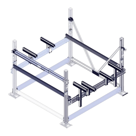
  9. Floe MAXIS User manual

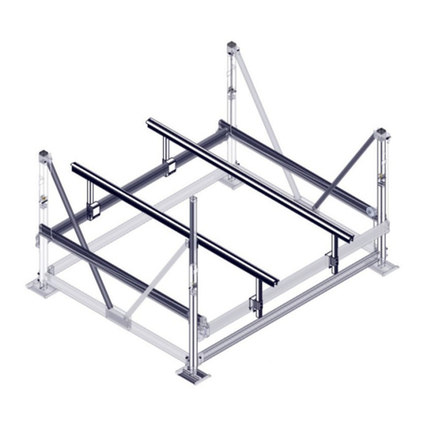
Floe MAXIS User manual

Other Floe Boating Equipment manuals

Floe VSD 6000 User manual

Floe

Floe VSD 6000 User manual

Floe VSD 6-8000 User manual

Floe

Floe VSD 6-8000 User manual

Floe 510-27100-00 Quick start guide

Floe

Floe 510-27100-00 Quick start guide

Floe V1600 PWC User manual

Floe

Floe V1600 PWC User manual

Floe 510-27300-00 Quick start guide

Floe

Floe 510-27300-00 Quick start guide

Floe 510-27400-00 Quick start guide

Floe

Floe 510-27400-00 Quick start guide

Floe VSD6500 User manual

Floe

Floe VSD6500 User manual

Floe VSD 6000 User manual

Floe

Floe VSD 6000 User manual

Floe VSD Guide

Floe

Floe VSD Guide

Floe VSD 6000 User manual

Floe

Floe VSD 6000 User manual

Floe FULL LENGTH BUNKS User manual

Floe

Floe FULL LENGTH BUNKS User manual

Floe 510-27500-00 Quick start guide

Floe

Floe 510-27500-00 Quick start guide

Floe SHOREWAY QUICK PIVOT User manual

Floe

Floe SHOREWAY QUICK PIVOT User manual

Floe 510-20000-00 User manual

Floe

Floe 510-20000-00 User manual

Floe INSTA-FLOAT Product manual

Floe

Floe INSTA-FLOAT Product manual

Floe 510-27200-00 Quick start guide

Floe

Floe 510-27200-00 Quick start guide

Floe V-2000 User manual

Floe

Floe V-2000 User manual

Floe X-SHALLOW 510-17100-00 Quick start guide

Floe

Floe X-SHALLOW 510-17100-00 Quick start guide

Floe 510-17700-00 User manual

Floe

Floe 510-17700-00 User manual

Floe VSD 5000 User manual

Floe

Floe VSD 5000 User manual

Floe 510-89304-00 User manual

Floe

Floe 510-89304-00 User manual

Floe PONTOON CRADLE PADS User manual

Floe

Floe PONTOON CRADLE PADS User manual

Floe VSD 8000 User manual

Floe

Floe VSD 8000 User manual

Floe V1600 PWC User manual

Floe

Floe V1600 PWC User manual
Popular Boating Equipment manuals by other brands

SureShade RTX Installation instructions manual

SureShade

SureShade RTX Installation instructions manual

Ideal Windlass CWM Installation, operation & maintenance instructions

Ideal Windlass

Ideal Windlass CWM Installation, operation & maintenance instructions

Access BIMINI Assembly instructions

Access

Access BIMINI Assembly instructions

Exalto 240BS manual

Exalto

Exalto 240BS manual

Faun C40 Trackway user manual

Faun

Faun C40 Trackway user manual

Humphree HCS-5 installation manual

Humphree

Humphree HCS-5 installation manual

Vetus BOW4512D Operation manual and installation instructions

Vetus

Vetus BOW4512D Operation manual and installation instructions

Dock Doctors SLIDING BOARDING STEP Assembly instructions

Dock Doctors

Dock Doctors SLIDING BOARDING STEP Assembly instructions

Mastervolt Mass Combi 12/2000-100 Quick installation

Mastervolt

Mastervolt Mass Combi 12/2000-100 Quick installation

SeaView PM5-FMD-8 installation instructions

SeaView

SeaView PM5-FMD-8 installation instructions

Hobie Mirage 360 manual

Hobie

Hobie Mirage 360 manual

Zattini Group bamar BOXTRON E14S Use and maintenance instruction manual

Zattini Group

Zattini Group bamar BOXTRON E14S Use and maintenance instruction manual

Hobie Getaway Hatch instructions

Hobie

Hobie Getaway Hatch instructions

NUCANOE 3005 Assembly instructions

NUCANOE

NUCANOE 3005 Assembly instructions

Westland T-Top Console Cover installation manual

Westland

Westland T-Top Console Cover installation manual

Furuno TZTL12F installation manual

Furuno

Furuno TZTL12F installation manual

ShoreLand'r DUB 2314 install guide

ShoreLand'r

ShoreLand'r DUB 2314 install guide

Wichard Gyb'Eas manual

Wichard

Wichard Gyb'Eas manual

manuals.online logo
manuals.online logoBrands
  • About & Mission
  • Contact us
  • Privacy Policy
  • Terms and Conditions

Copyright 2025 Manuals.Online. All Rights Reserved.

SHEET 1 OF 8
FLOE MAXIS EXTENSION KIT 6-10K
ASSEMBLY INSTRUCTIONS
KIT P/N 512-65030-00
TOOLS REQUIRED
-9/16” SOCKET/WRENCH
-3/4” SOCKET/WRENCH
-TORQUE WRENCH
-TAPE MEASURE
INSTRUCTION P/N: 611
-
6
5030
-
00
RELEASED 06/12/19
© Manufactured by:
Floe International Inc.
48473 State Hwy. 65
McGregor, MN 55362
www.floeintl.com
*LIFT
AND CANOPY
N
OT INCLUDED
SHEET 2 OF 8
BILL OF MATERIALS/EXPLODED VIEW
P/N 512-65030-00
KIT, MAXIS EXTENSION 6-10K
NUMBER PART NUMBER QTY. DESCRIPTION
1 001-70207-00 2 HHCS, ½-13 x 1 ¼” 18-8 ss
2 001-71021-00 2 FLAT WASHER, ½” 18-8 SS
3 001-76072-00 2 NUT, NYLOCK ½-13 ALUM.
4 002-00257-00 2 TUBE, MAXIS LEG EXTENSION 6-10K – 12”
5 002-00258-00 2 INSERT, CANOPY 6-10K W/ PIVOT HOLE – 44”
6 112-01075-00 2 ASS’Y, CANOPY INSERT W/ GUIDE HOLES – 44”
SHEET 3 OF 8
STEP 1
IF INSTALLED, REMOVE VINYL CAP FROM TOP OF EACH CORNER POST. USE A ½” X 1-1/4” BOLT
AND ½” WASHER FROM CANOPY HOOP HARDWARE (FIGURE 1.1). PLACE THE BOLT AND WASHER
INTO THE CORNER POST (FIGURE 1.2). SLIDE AN INSERT INTO EACH OF THE CORNER POSTS, THEN
START A ½” NYLOCK NUT (INCLUDED WITH CANOPY HOOP HARDWARE) ON THE BOLT, BUT DO
NOT TORQUE. CORNER POSTS ON THE TILTING SIDE USE INSERT P/N 002-00258-00 (ONE
THROUGH HOLE) (FIGURE 1.3). CORNER POSTS ON THE NON-TILTING SIDE USE THE INSERT P/N
112-01075-00 (TWO THROUGH HOLES) (FIGURE 1.4).
FIGURE 1.1
FIGURE 1.2
FIGURE 1.3
FIGURE 1.4
SHEET 4 OF 8
THE MAXIMUM HEIGHT OF THE INSERTS IS 38” (6” OF ENGAGEMENT IN THE CORNER POSTS). THE
MINIMUM HEIGHT OF THE INSERTS IS 26” (18” OF ENGAGEMENT IN THE CORNER POSTS) (FIGURE
1.5). TORQUE ½” NUT TO 60 FT-LBS (FIGURE 1.6). PROCEED TO INSTALL MAXIS CANOPY BY
REFERRING TO MAXIS CANOPY FRAME INSTRUCTIONS.
FIGURE 1.5
SHEET 5 OF 8
STEP 2 (IF INSTALLING MAXIS TILTING CANOPY)
INSTALL (1) ½” X 1 1/4” BOLT AND (1) ½” WASHER INTO EXTENSION TUBE. NOTE THAT THE
EXTENSION TUBE IS SLID OVER THE INSERTS ON THE NON-TILTING SIDE. DEPENDING ON THE
CONFIGURATION, IT IS EITHER ON THE MOTOR SIDE (CORNER POSTS “B” & “C”) OR THE LIFTING
SIDE (CORNER POSTS “A” & “D”). FOR EITHER CONFIGURATION, IT IS ALWAYS THE INSERT WITH
TWO THROUGH HOLES (112-01075-00) (FIGURE 2.1). START (1) ½” NYLOCK NUT ON THE ½” BOLT,
BUT DO NOT TORQUE. THEN, SLIDE EXTENSION ONTO INSERT (FIGURE 2.2).
FIGURE 2.1
FIGURE 2.2
SHEET 6 OF 8
FIRST, SET HEIGHT OF EXTENSION TUBE 7-3/8” FROM TOP OF CORNER POST. THEN, SWING LOWER
ACTUATOR MOUNT AND ACTUATOR TOWARDS EXTENSION TUBE (FIGURE 2.3). EXTENSION TUBE
WILL BE APPROXIMATELY 5-3/16” FROM TOP OF TUBE TO TOP OF ACTUATOR MOUNT. TORQUE 60
FT-LBS (FIGURE 2.4).
FIGURE 2.3
FIGURE 2.4
SHEET 7 OF 8
NOTE (MAXIS TILT KIT INSTALLATIONS)
SHEET 8 OF 8