Skipper CD401MR-SC Specification sheet

CD401MR-SC
Operation and Installation Manual
Multi Repeater
Document no: DM-R006-SC
Rev: 2242
for sw version 1.6x
Date: 2022-09-26
SKIPPER Electronics AS www.skipper.no
Enebakkveien 150 Telephone:+47 23 30 22 70
P. O. Box 151, Manglerud E-mail: support@skipper.no
0612 Oslo, Norway Co. reg. no: NO-965378847-MVA

Operation and Installation CD401MR-SC
Date: 2022-09-26Page 2 of 48
Weitergabe sowie vervielfältigung dieser unterlage,
verwertung und mitteilung ihres inhaltes nicht
gestattet, soweit nicht ausdrücklich zugestanden.
Zuwiderhandlungen verpichten zu schadenersatz.
Toute communication ou reproduction de ce
document, toute exploitation ou communication de ou
son contenu sont interdites, sauf autorisation expresse.
Tout manquement à cette règle est illicite et expose
son auteur au versement de dommeges et intèrèts.
Copying of this document, and giving it to others
and the use or communication of contents thereof,
are forbidden without express authority. Oenders
are liable to the payment of damages.
Sin nuestra expresa autorización, queda
terminantemente prohibida la reproducción
total o parcial de este documento, asì como su
uso indebido y/o su exhibición o comunicación
a terceros. De los infractores se exigirá el
correspondiente resarcimiento de daños y
perjuicios.
CD401MR-SC
Operation and Installation Manual

Date: 2022-09-26 Page 3 of 48
Operation and Installation CD401MR-SC
TABLE OF CONTENTS
Overview. 5
TermInology. Terms used in this manual 6
Units 6
Abbreviations 6
Introduction. The Multi Repeater 7
Chapter 1. Physical installation 8
The Dimming Inputs 9
Chapter 2. Setting up and using the Compact Multi Repeater Display 10
Principles 10
Runtime screens 10
Menu screens 10
Shifting screens 10
Activating the runtime screens 11
Menu Diagram 12
Setup of inputs 14
Changing of the baud rate 14
Demo mode 14
Master Reset (Factory Default Settings) 14
15
Runtime screens 15
Accepted NMEA sentences 15
Conguration and operational screen 16
Conguring of screens 16
Depth 17
Speed 18
Distance 19
Heading 20
Rotation 21
Pitch and Roll 22
Wind 23
Temperature 25
Drive 26
Clock/UTC 27
Display Dimming Control 27
Auxillary 28

Operation and Installation CD401MR-SC
Date: 2022-09-26Page 4 of 48
Error Handling 29
Chapter 4. Maintenance 30
Routine maintenance 30
Checking your version 30
Firmware upgrade 30
Mounting the Multi Repeater facing aft. 30
Appendix 1. 31
Specications and mechanical drawing 31
System specication 31
Display 31
inputs/outputs 31
Mechanical dimentions 32
Appendix 2. 33
Accepted NMEA 0183 sentences Summary 33
output NMEA 0183 sentences Summary 35
Detailed description 36
Appendix 3. 44
Compact display CD401 options 44
Converting the CD401 system 45
Cabling CD401MR-SC vs. CD401MR-SB 46
Notes: 47

Date: 2022-09-26 Page 5 of 48
Operation and Installation CD401MR-SC
OVERVIEW.
_____________________________________________________________________
Terminology
Terms, units and abbreviations used in this manual.
Introduction
This part introduces you to the elements of the Multi Repeater (MR) system.
Chapter 1 – Physical installation
Correct installation of the system will ensure problem free service for many years.
This section explains the main steps to get your system working.
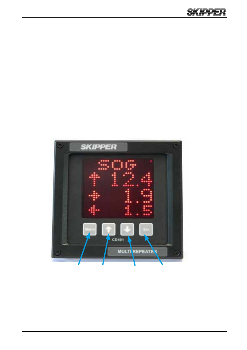
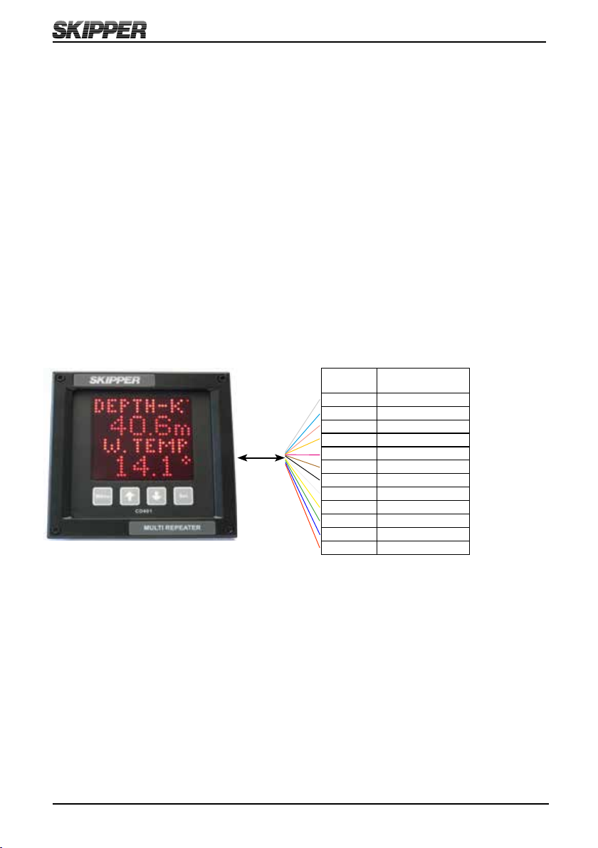
Chapter 2 – Setting up and using the Compact Multi Repeater display
The Compact Multi Repeater display is a exible intuitive display allowing data to be
displayed in a user friendly way. It is also a primary system and can be integrated into
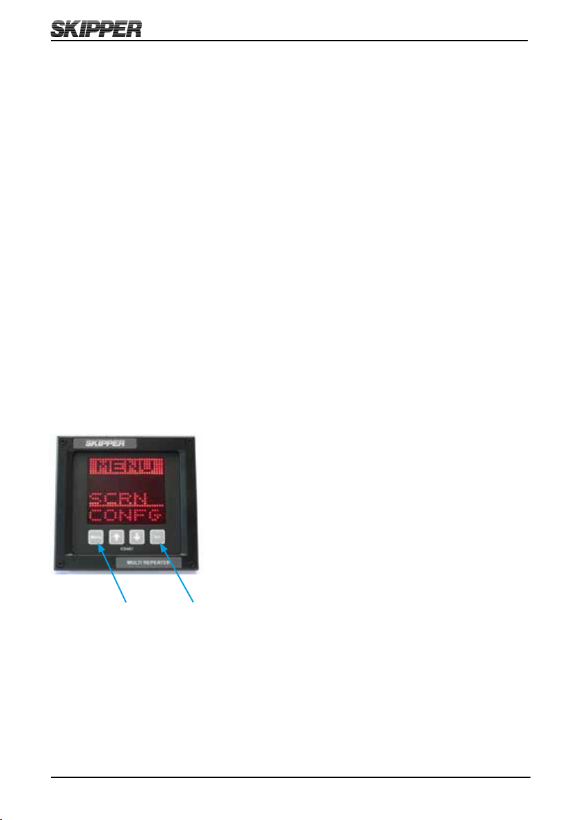
the navigation system as regulation stipulate. This chapter explains how to set up the
unit.
Chapter 3 – Operation
Once the system is installed and operational, the user can change the screen to show
the data of interest at any time. This section explains the operation of the system.
Chapter 4 – Maintenance
It is a good idea to verify your systems performance from time to time. This chapter
describes how to check interfaces and other issues. In the event of malfunction, this is
a good place to start for trouble shooting.
Here you will nd more details of how the system works and which factors are
important to know when using it.
Appendix 2 – Accepted NMEA sentences
This section describes the inputs accepted by the Compact Multi Repeater display in
this conguration
The Compact can be used in a number of dierent system both as a repeater and a
speed log. This section explains what is available and how to activate the options.

Operation and Installation CD401MR-SC
Date: 2022-09-26Page 6 of 48
TERMINOLOGY. Terms used in this manual
_____________________________________________________________________
Unless otherwise stated, all values shown on the display are as follows:
Depth Meters
Speed Nautical miles per hour (knots)
Distance Nautical miles (nm)
Heading Degrees (0 – 359.9o)
Rotation Degrees per minute (o/min)
Pitch and roll Degrees (0 – 359.9o)
Wind Nautical miles per hour (knots)
Meter per seconds (m/s)
Beaufort (Bft)
Temperature Degrees Celcius (oC)
Speed revolutions Revolutions per minute (rev/min)
Rudder angle Degrees (0 – 359.9o)
Propeller pitch Percentage of maximum (0 -100 %)
Clock /UTC hh:mm (00:00 – 23:59)
In addition the following symbols are used on the runtime screens:
TPDaily trip (in nm)
TLTotal measured distance travelled (in nm)
oDegrees
% Percentage
←↑→↓ Direction

Date: 2022-09-26 Page 7 of 48
Operation and Installation CD401MR-SC
INTRODUCTION. The Multi Repeater
_____________________________________________________________________
The SKIPPER Multi Repeater allow important values from a variety of systems to be
displayed anywhere on the vessel. The CD401 Compact display is unique in its simple
and exible way to display vital data in almost all conditions, from no light to bright
sunlight. In addition, it is classed to IP 56 allowing it to be mounted outside and used
in any conditions. The unit is a standard 144 mm format allowing it to be mounted in
tight spaces or overhead.
MENU Up (↑) Down (↓) SET

Operation and Installation CD401MR-SC
Date: 2022-09-26Page 8 of 48
CHAPTER 1. Physical installation
____________________________________________________________________
The Multi Repeater CD401MR is a stand alone unit and does not require additional
circuitry. It should be supplied by a 24 V (19 V-36 V) 25 W DC supply and the cabling
of the system is as per diagram below. The unit is supplied with 2 m of cable (12 core).
This can be extended without problem. Only the wires in use need extending.
Note: Mounting drawing is available in Appendix 1.
Color
Codes
Signals
Grey NMEA OUT A
Turquoise NMEA OUT B
Pink NMEA2 IN A
Orange NMEA2 IN B
Violet DIM DWN B
Brown DIM DWN A
Black DIM UP B
White DIM UP A
Yellow NMEA IN A
Green NMEA IN B
Blue 0 V
Red +24 V
2 m
NOTE
Compared to the CD401MR-SA/SB variants NMEA, A and B are switched , and
NMEA out is replaced by NMEA 1 in this version (See appendix 3.)

Date: 2022-09-26 Page 9 of 48
Operation and Installation CD401MR-SC
Pulses of at least 60 ms on the dimming up and dimming down cables will cause the
dimming to change by one level. The inputs are optocoupled and therefore require an
external voltage to operate, (5 Volt -24 Volt (Typically 5/12/24 Volt)).
A
A
B
B
C
C
D
D
E
E
F
F
G
G
H
H
1 1
2 2
3 3
4 4
5 5
6 6
SSUUGGGGEESSTTEEDDIINNTTEERRFFAACCEEMMEETTHHOODDSSFFOORRDDIIMMMMIINNGGCCOONNTTRROOLL
All Diming Inputs DIMnnn
Input Voltage VCC 5 - 24 V
CCDD440011LLRR//MMRRIINNTTEERRNNAALLCCIIRRCCUUIITTSS,,SSIIMMPPLLIIFFIIEEDD
AAlltteerrnnaattiivveess
RReeccoommmmeennddeedd
2008.11.13 ØK 2022.09.19 JER
Misc_IO_Examples
SC version NMEA Changes
CD_4015/5 A
B
E
C
BC847A
T400
0805
21
100R
R400
A
CA
a
BAV99
D400
2
3
8
7
5
HCPL0201
PH400
1206
1K0
R401
DIMnnnB
DIMnnnA
B
E
C
G
D
S
1
2
4
3
VCC VCC VCC VCC
0805
X7R
1
2
100n
21
0805
C0G
2
1
100p
21
BLM21A10
0805
C0G
2
1
100p
ENA
ENA
INA
INB
OUTA+
QQuuaadd442222
DDrriivveerr__aa
OUTA-
OUTB+
OUTB-
VCC
VSS
4
12
1
7
2
3
6
5
16
8
DS26C31TM
+5V
B
E
CBC847A
A
CA
BAV99
2
3
8
7
5
HCPL0201
0805
12
100R
0805
12
300R
NMxOUTB
NMxOUTA
NM2OUTA
NM2OUTB
NM2INA
NM2INB
DIMDWNB
DIMDWNA
DIMUPB
DIMUPA
NM2INA(Pink)
(Yellow)
(Green)
NM2OUTA(Grey)
NM2OUTB(Turqoise)
+24V (Red)
-24V
NMEAINB
NMEAINA
(Blue)
DIMUPB (Black)
DIMUPA (White)
DIMDWNA (Brown)
DIMDWNB (Violet)
NM2INB(Orange)
12
11
10
9
8
7
6
5
4
3
2
1
J101
TJC3_12_90

Operation and Installation CD401MR-SC
Date: 2022-09-26Page 10 of 48
CHAPTER 2. Setting up and using the
Compact Multi Repeater Display
_____________________________________________________________________
The Compact Multi Repeater Display is a exible dot matrix LED display designed
to display navigation data. The Multi Repeater can be user programmed to show most
kinds of numerical data from NMEA messages. The Compact has three user denable
alphanumeric displays, each allowing up to 4 lines to be displayed.
The Compact Display starts up in runtime mode. By pressing the MENU button, the
preset runtime screens can be selected. The unit can be dimmed in any of the runtime
screens using the UP (↑) and DOWN (↓) buttons.
To change the setup of the Multi Repeater, the user must simultaneously press MENU
and SET buttons. This will give access to a menu system allowing the user to scroll
up and down the sub menus and functions using UP and DOWN, and SET button to
select. To move back and up a menu, the MENU button must be pressed. The middle
underlined line is the selected line. The other lines are dimmed.
The menu structure is shown in the MENU DIAGRAM.
Press both MENU and SET buttons to activate the menus. Press and hold MENU to
return to runtime screen.
The system can be made to shift, with a ve second period, between the activated
screens. Pressing MENU will pause this function, and holding MENU will reactivate it.

Date: 2022-09-26 Page 11 of 48
Operation and Installation CD401MR-SC
The system has three user preset runtime screens (SCR1, SCR2, SCR3). The Screen
Menu allows the user to congure and choose which runtime screens to be included in
normal operation. UP and DOWN buttons will scroll to the available screens. By using
the SET button, the user can control each individual screen to ON, OFF or SHIFTING.
Screens set to ON are available to be displayed by pressing the MENU button. Screens
set to OFF will not be displayed. Screens set to SHIFTING will be shown on the
display periodically. Each shifting runtime screen will
be displayed for 5 seconds.
ON
SHIFTING
OFF
If any screens are congured to SHIFTING, these selected screens will automatically
start displaying periodically. The shifting of these preset runtime screens are stopped
if the MENU button is pressed in runtime mode. By holding down the MENU button
longer, the shifting will be started again.

Operation and Installation CD401MR-SC
Date: 2022-09-26Page 12 of 48
Screens (SCRN)
Select runtime screens
▲ Next sub menu
▼ Prev sub menu
SET select sub menu
MENU return
Screens (SCRN)
▲Next runtime screen
▼ Prev runtime screen
SET activate/deactivate/
shifting runtime screens
SCR1
SCR2
SCR3
TRIP
INFO
Change the messages being
displayed on each user screen
▲Next sub menu
▼ Prev sub menu
SET select sub menu
MENU return
▲Change display message
▼ Change display message
SET move to next position on screen
CFG 1
CFG 2
CFG 3

Date: 2022-09-26 Page 13 of 48
Operation and Installation CD401MR-SC
System setup (SETUP)
Setup the system
parameters
▲Next sub menu
▼ Prev sub menu
SET select sub menu
MENU return
Baud settings (NMEA)
▲Higher value
▼ Lower value
Menus, scrollable menu system
Accessed with SET and MENU pressed simultaneously
▲Next sub menu
▼ Prev sub menu
SET select sub menu
MENU return
Diagnostics/advanced setup (DIAG)
Diagnose and adjust less used parameters
▲Next sub menu
▼ Prev sub menu
SET select sub menu
MENU return
Code option activation (CODE)
Shows serial no
Code number with active digit underlined
▲Increment underlined digit
▼ Move to next digit
SET activates the displayed code
Upgrade mode (UPGRD)
Allow the system to upgrade from cable
Demo (DEMO)
▲Increment mode
▼ Decrement mode
MENU accept mode
Mode 1 = dynamic
Mode 2, 3 = static
O
Splash screen (INFO)
▲ Dimming up
▼ Dimming down
Option info
Software version
Self tests (TEST)
▲ Next test
▼ Previous test
SET starts selected test

Operation and Installation CD401MR-SC
Date: 2022-09-26Page 14 of 48
The system will allow many NMEA formats to be displayed. No setup is required. The
system has 2 input channels, both of these may be used.
The NMEA (IEC61162-1) standard is 4800 baud. Some vessels run with higher baud
rates. 4800, 9600, 19200, 38400, 57600 and 115200 baud rates can be selected in the
baud screen of the setup menu.
A demo mode is available, and can be activated with MENU button in the diagnostics
menu. Three modes are available.
• Mode 1 is a dynamic demo mode taking the present values as the start point and
slowly varying all the available values.
• Mode 2 is a static mode taking the present values and keeping them active.
• Mode 3 is a longitudinal 5 kn, transversal 1 kn.
When the demo mode is active, alarms will be disabled, and the screen will indicate the
demo state with a blinking S in the upper right corner. The user can turn o the demo
mode from the demo screen, or by recycling the power. The demo mode will turn o
automatically after 10 hours.
The factory default settings can be restored by performing the following operations:
1. Select CODE in diagnostic (DIAG) menu.
2. Press the SET button (Note: Do not change code value).
The unit will now restart with factory default settings.

Date: 2022-09-26 Page 15 of 48
Operation and Installation CD401MR-SC
CHAPTER 3. Conguring the screens
_____________________________________________________________________
The unit starts up in runtime mode. By pressing the MENU button, the preset runtime
screens (SCR1, SCR2, SCR3) can be selected. The unit can be dimmed in any of the
runtime screens using the UP (↑) and DOWN (↓) buttons. If Trip/Total are selected as a
displayed parameter, they can be toggled using the SET button. If wind speed is selected
as a displayed parameter, the unit can be toggled between knots, m/s, or Beaufort
using the SET button. The Set button is used to reset the Trip counter if Trip Screen
is displayed and the Multi Repeater is connected to a SKIPPER EML 224 system or a
DL850 270 kHz system.
When using the Compact Display as a Multi Repeater, the display could be user
programmed to show the most commonly used NMEA 0183 (IEC61162) messages for:
Depth Below surface, keel and transducer
Speed Over ground and through water (longitudinal, transverse, aft and
relative)
Distance Total/trip for both ground and water
Heading True, magnetic and relative
Rotation Rate of turn and direction
Pitch and roll In degrees
Wind Speed and direction (true, magnetic and relative)
Temperature Water and air
Drive RPM (Revolutions Per Minute), propeller pitch and rudder position
Clock UTC (Universal Time Coordinated), local time and Expected Time
of Arrival (ETA)
Dimming Display dimming
Auxillary User dened NMEA messages
A summary of supported NMEA sentences is listed in Appendix 2.
INFO Screen TRIP Screen

Operation and Installation CD401MR-SC
Date: 2022-09-26Page 16 of 48
The programming of parameters to show on the screen is very exible. It is advise to
add leading text before the parameters and not mixing too many dierent messages. A
typical conguration is to show two related parameters on the screen simultaneously
with leading text. Arrows are added to some parameters for better readability. Press
MENU and SET button simultaneously to enter the screen menus, select CONFG and
then select wanted screen menu (CFG1, CFG2 or CFG3) to start to congure wanted
screen menu. See chapter 2 ”Setting up and using the Compact Display” on how to
program the display to show wanted information on the screen.
The 3 user programmable screen menus can be set up using
the Cong (CONFG) menu. This submenu allows the user
to select one of the three screen menus, and on entering
the Cong screen menu, the user can change the data type
to be displayed in each of the 4 screen menu’s positions.
UP (↑) and DOWN (↓) will change the data type, SET will
move to the next screen menu position.
Placing text (TXT) in the bottom 4th line or 3rd and 4th line will cause the data to spread
out showing fewer data points. The system will not allow you to mix speed data from
dierent sources on the same screen. Having two text (TXT) lines after each other will
also rearrange the positioning. (See examples on next page).
The non-active parameters will continue showing the dimmed present data, when not
selected. Some combinations of data are not allowed, as they may cause confusion.
These will be automatically corrected. Note that the leading text is identical for some
data, and information about talkers are ignored. Regulations require the user to be able
to identify which data they are looking at. This can be achieved by using the TXT
function or a sticker on the unit.

Date: 2022-09-26 Page 17 of 48
Operation and Installation CD401MR-SC
Depth
The NMEA sentences DPT, DBS, DBT, DBK and PSKPDPT are all supported for
receiving information about the depth. The use of the DPT sentence is recommended
when available. Depth values in feet and fathoms (from DBK, DBT and DBS) are
converted to meters. The screen will display either DEPTH-S (depth below surface),
DEPTH-T (depth below Transducer) or DEPTH-K (depth below keel) depending of
the received sentences (DBS, DBT or DBK) or the oset value in DPT. The proprietary
sentence PSKPDPT is able to distinguish between both transducer location and channel
number. The transducer location is indicated by an arrow in the text line. The channel
number is selected by parameter PDPT1, PDPT2 or PDPT3 and is written in the text
line as DPT1, DPT2 or DPT3 respectively for each channel. The parameter name PDPT
will ignore channel number and is written in the text line as DEPTH.
The depth is always displayed in meters. Depth values below 10 meters are displayed
with 2 decimals, depth values between 10 and 100 meters are displayed with 1 decimal
and depth above 100 meters are displayed without decimals.
Maximum depth value to be displayed is 9999 meters.
screen:
Runtime
screen:

Operation and Installation CD401MR-SC
Date: 2022-09-26Page 18 of 48
Speed
The NMEA sentence VBW is supported for receiving information about the speed
through water and speed over ground (bottom) for longitudinal, transverse and transverse
aft. The NMEA sentences VHW and VTG are supported for receiving information about
relative speed.
• An arrow, indicating the direction, is added in front of the value for speed values
from the NMEA sentences VBW.In the case of 2 VBW messages from separate
SOG and STW sensors, both can be used as long as the unused elds are left blank.
(DL21, EML and SL1200 etc.)
• The relative is fetched from the NMEA sentence VHW.
• The relative speed over ground is fetched from the NMEA sentence VTG.
• Speed value in km/h is converted to knots if speed value in knots is not available.
• Relative speed is displayed without arrows.
• All speed values are displayed in knots with either one or two decimals depending
of the congured parameter to display. STW2L, STW2T, SOG2L and SOG2T will
always display speed below 10 knots with two decimals and speed from 10 knots
and above with one decimal. All other speed parameters are displayed with one
decimal (see the detailed description of the parameters in Appendix 2). Maximum
speed value to be displayed is +/- 99.9 knots.
screen:
Runtime
screen:
T

Date: 2022-09-26 Page 19 of 48
Operation and Installation CD401MR-SC
Distance
The NMEA sentence VLW are supported for receiving information about distances. The
Trip/Total parameters for either water distance or ground distance can be toggled using
the SET button.
The distance values are always displayed in nautical miles and the value will wrap
around after reaching the maximum value of 99999. Total/trip values below 10 are
displayed with two decimals, values between 10 and 1000 with one decimal and values
above 1000 are displayed with no decimals.
screen:
Runtime screen:

Operation and Installation CD401MR-SC
Date: 2022-09-26Page 20 of 48
Heading
The NMEA sentences VHW, VTG, THS, HDT, HDM and HDG are all supported for
receiving information about the heading. It is recommended to use THS instead of HDT,
and HDG instead of HDM when available. The deviation and variation parameters in
HDT are ignored.
If the same heading parameter is received from dierent talkers, the heading parameter
will be prioritized as shown below:
1. Gyro, north seeking (HE).
2. GPS (GP).
3. Compass, magnetic (HC).
4. Others.
An arrow is added on the text line to indicate which direction the bow turns. If no
change in heading from previous value, no arrow is displayed.
The heading value is always displayed with one decimal. Legal range for the heading to
be displayed, are values in the range from 0 to 359.9o.
screen:
Runtime
screen:
Direction of turn is to
port.
Direction of turn is to
starboard.
No change in
heading since last
message.
Table of contents
Other Skipper Repeater manuals