VMIC VMIVME-5531L User manual
Artisan Technology Group is your source for quality
new and certied-used/pre-owned equipment
• FAST SHIPPING AND
DELIVERY
• TENS OF THOUSANDS OF
IN-STOCK ITEMS
• EQUIPMENT DEMOS
• HUNDREDS OF
MANUFACTURERS
SUPPORTED
• LEASING/MONTHLY
RENTALS
• ITAR CERTIFIED
SECURE ASSET SOLUTIONS
SERVICE CENTER REPAIRS
Experienced engineers and technicians on staff
at our full-service, in-house repair center
WE BUY USED EQUIPMENT
Sell your excess, underutilized, and idle used equipment
We also offer credit for buy-backs and trade-ins
www.artisantg.com/WeBuyEquipment
REMOTE INSPECTION
Remotely inspect equipment before purchasing with
our interactive website at www.instraview.com
LOOKING FOR MORE INFORMATION?
Visit us on the web at www.artisantg.com for more
information on price quotations, drivers, technical
specications, manuals, and documentation
Contact us: (888) 88-SOURCE | sales@artisantg.com | www.artisantg.com
SM
View
Instra

VMIVME-5531L VMEbus
FIBER-OPTIC REPEATER LINK
PRODUCT MANUAL
DOCUMENT NO. 500-005531-000 B
Revised December 21, 1995
VME MICROSYSTEMS INTERNATIONAL CORPORATION
12090 SOUTH MEMORIAL PARKWAY
HUNTSVILLE, ALABAMA 35803-3308
(205) 880-0444
1-800-322-3616
Artisan Technology Group - Quality Instrumentation ... Guaranteed | (888) 88-SOURCE | www.artisantg.com

NOTICE
The information in this document has been carefully checked and is
believed to be entirely reliable. While all reasonable efforts to ensure accuracy
have been taken in the preparation of this manual, VMIC assumes no
responsibility resulting from omissions or errors in this manual, or from the use of
information contained herein.
VMIC reserves the rightto make any changes, withoutnotice,to thisor
any of VMIC’s products to improve reliability, performance, function, or design.
VMIC does not assume any liability arising out of the application or use
of any product or circuit described herein; nor does VMIC convey any license
under its patent rights or the rights of others.
For warranty and repair policies, refer to VMIC’s Standard Conditions
of Sale.
AMXbus, BITMODULE, COSMODULE, DMAbus, IOWorks, IOWorks
Access, IOWorks Foundation, MAGICWARE, MEGAMODULE, PLC
ACCELERATOR, QUICK-R-NET, Soft Logic Link, SRTbus, TESTCAL, “The Next
Generation PLC”, The PLC Connection, TURBOMODULE, UCLIO, UIOD, UPLC,
Visual IOWorks, Visual Soft Logic Control,
VMEaccess
,
VMEmanager
,
VMEmonitor
, VMEnet, VMEnet II,
VMEprobe
, and
WinUIOC
are trademarks of
VME Microsystems International Corporation. The VMIC logo, I/O man figure,
and UIOC are registered trademarks of VME Microsystems International
Corporation. Other registered trademarks are the property oftheir respective
owners.
VME Microsystems International Corporation
All Rights Reserved
This document shall not be duplicated, nor its contents used for any
purpose, unless granted express written permission from VMIC.
Copyright © February 1993 by
VME Microsystems International Corporation
Artisan Technology Group - Quality Instrumentation ... Guaranteed | (888) 88-SOURCE | www.artisantg.com

DOC. NO. 500-005531-000 B
A
B
04/19/94
12/21/95
Release
Changes per ECO Pages v, vi, 1-1, 1-2,
1-3, 3-1, 3-6, 3-7, 6-1
94-0546
96-0052
RECORD OF REVISIONS
REVISION
LETTER DATE PAGES INVOLVED CHANGE NUMBER
VME MICROSYSTEMS INT'L CORP. PAGE NO.REV LTR
12090 South Memorial Parkway •
Huntsville, AL 35803-3308 (205) 880-0444 ii
Artisan Technology Group - Quality Instrumentation ... Guaranteed | (888) 88-SOURCE | www.artisantg.com

iii
VMIC
SAFETY SUMMARY
THE FOLLOWING GENERAL SAFETY PRECAUTIONS MUST BE OBSERVED DURING ALL
PHASES OF THE OPERATION, SERVICE, AND REPAIR OF THIS PRODUCT. FAILURE TO
COMPLY WITH THESE PRECAUTIONS OR WITH SPECIFIC WARNINGS ELSEWHERE IN THIS
MANUAL VIOLATES SAFETY STANDARDS OF DESIGN, MANUFACTURE, AND INTENDED USE
OF THIS PRODUCT. VME MICROSYSTEMS INTERNATIONAL CORPORATION ASSUMES NO
LIABILITY FOR THE CUSTOMER’S FAILURE TO COMPLY WITH THESE REQUIREMENTS.
GROUND THE SYSTEM
To minimize shock hazard, the chassis and system cabinet must be connected to an
electrical ground. A three-conductor AC power cable should be used. The power
cable must either be plugged into an approved three-contact electrical outlet or used
with a three-contact to two-contact adapter with the grounding wire (green) firmly
connected to an electrical ground (safety ground) at the power outlet.
DO NOT OPERATE IN AN EXPLOSIVE ATMOSPHERE
Do not operate the system in the presence of flammable gases or fumes. Operation of
any electrical system in such an environment constitutes a definite safety hazard.
KEEP AWAY FROM LIVE CIRCUITS
Operating personnel must not remove product covers. Component replacement and
internal adjustments must be made by qualified maintenance personnel. Do not
replace components with power cable connected. Under certain conditions,
dangerous voltages may exist even with the power cable removed. To avoid injuries,
always disconnect power and discharge circuits before touching them.
DO NOT SERVICE OR ADJUST ALONE
Do not attempt internal service or adjustment unless another person, capable of
rendering first aid and resuscitation, is present.
DO NOT SUBSTITUTE PARTS OR MODIFY SYSTEM
Because of the danger of introducing additional hazards, do not install substitute parts
or perform any unauthorized modification to the product. Return the product to VME
Microsystems International Corporation for service and repair to ensure that safety
features are maintained.
DANGEROUS PROCEDURE WARNINGS
Warnings, such as the example below, precede only potentially dangerous
procedures throughout this manual. Instructions contained in the warnings must be
followed.
WARNING
DANGEROUS VOLTAGES, CAPABLE OF CAUSING DEATH, ARE PRESENT IN THIS SYSTEM.
USE EXTREME CAUTION WHEN HANDLING, TESTING, AND ADJUSTING.
Artisan Technology Group - Quality Instrumentation ... Guaranteed | (888) 88-SOURCE | www.artisantg.com
iv
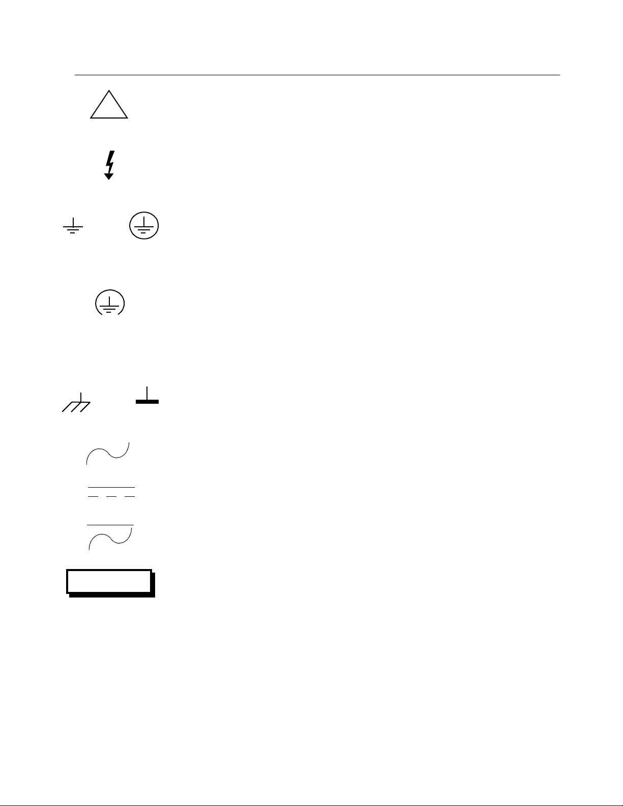
SAFETY SYMBOLS
GENERAL DEFINITIONS OF SAFETY SYMBOLS USED IN THIS MANUAL
OR
***************
***************
*
*
**
*
*
CAUTION
NOTE:
WARNING
!
OR
Instruction manual symbol:the productis marked with this symbol when it
is necessary for the user to refer to the instruction manual in order to
protect against damage to the system.
Indicates dangerous voltage (terminals fed from the interior by voltage
exceeding 1000 volts are so marked).
Protective conductor terminal. For protection against electrical shock in
case of a fault. Used with field wiring terminals to indicate the terminal
which must be connected to ground before operating equipment.
Low-noise or noiseless,clean ground (earth) terminal. Used for a signal
common, as well as providing protection against electrical shock in case of
a fault.Before operating the equipment, terminal marked with this symbol
mustbe connected to ground in the manner described in the installation
(operation) manual.
Frame or chassis terminal. A connection to the frame (chassis) of the
equipment which normally includes all exposed metal structures.
Alternating current(power line).
Direct current (power line).
Alternating or direct current (power line).
The WARNING sign denotes a hazard. Itcalls attention to a procedure, a
practice, a condition, or the like, which, if not correctly performed or
adhered to,could result in injury or death to personnel.
The CAUTION sign denotes a hazard. It calls attention to an operating
procedure, a practice, a condition, or the like, which, if not correctly
performed or adhered to, could result in damage to or destruction of part or
all of the system.
The NOTE sign denotes importantinformation. Itcalls attention to a
procedure, a practice, a condition or the like, which is essential to highlight.
Artisan Technology Group - Quality Instrumentation ... Guaranteed | (888) 88-SOURCE | www.artisantg.com

500-005531-000
v
VMIVME-5531L VMEbus FIBER-OPTIC
REPEATER LINK
TABLE OF CONTENTS
Page
SECTION 1. INTRODUCTION
1.1 FEATURES FOR 6U BOARD ..............................................................1-1
1.2 FEATURES FOR 3U BOARD ..............................................................1-1
1.3 FUNCTIONAL DESCRIPTION.............................................................1-2
1.4 REFERENCE MATERIAL LIST............................................................1-2
SECTION 2. PHYSICAL DESCRIPTION AND SPECIFICATIONS
SECTION 3. THEORY OF OPERATION
3.1 OPERATIONAL OVERVIEW................................................................3-1
3.2 THEORY OF OPERATION ..................................................................3-7
3.3 BUS ARBITRATION SIGNALS ............................................................3-7
3.4 INTERRUPT SIGNALS ........................................................................3-7
SECTION 4. PROGRAMMING
4.1 PROGRAMMING..................................................................................4-1
SECTION 5. CONFIGURATION AND INSTALLATION
5.1 UNPACKING PROCEDURES..............................................................5-1
5.2 PHYSICAL INSTALLATION.................................................................5-1
5.3 BOARD CONFIGURATION..................................................................5-1
5.4 CABLE INSTALLATION.......................................................................5-2
SECTION 6. MAINTENANCE
6.1 MAINTENANCE ...................................................................................6-1
6.2 MAINTENANCE PRINTS.....................................................................6-1
Artisan Technology Group - Quality Instrumentation ... Guaranteed | (888) 88-SOURCE | www.artisantg.com

500-005531-000
vi
VMIVME-5531L VMEbus FIBER-OPTIC
REPEATER LINK
TABLE OF CONTENTS (CONTINUED)
LIST OF FIGURES
Figure Page
3.1-1 Single Link Application Configuration...................................................3-2
3.1-2 Star Configuration ................................................................................3-3
3.1-3 Block Diagram of VMIVME-5531M Primary Chassis
Repeater Link Board ............................................................................3-4
3.1-4 Block Diagram of VMIVME-5531S Secondary Chassis
Repeater Link Board ............................................................................3-5
3.1-5 Block Diagram of the VMIVME-5531S Secondary Chassis
Repeater Link Board (3U) ....................................................................3-6
5.5-1 VMIVME-5531L Cable Connection.......................................................5-3
APPENDIX
A Assembly Drawing, Parts List, and Schematic
Artisan Technology Group - Quality Instrumentation ... Guaranteed | (888) 88-SOURCE | www.artisantg.com

500-005531-000
1-1
SECTION 1
INTRODUCTION
1.1 FEATURES FOR 6U BOARD
VMIC’s VMIVME-5531L Fiber-Optic Repeater Link is a software transparent
two-board set, with interconnecting cables that allow the user to effectively extend a VMEbus
chassis to more than 20-slots. The "extended" slots, however, are only
operational for non-interrupting VMEbus slave modules. The extended slots will not
support VMEbus master modules.
The Repeater Link has several unique features, as listed below:
a. Software transparency, allows direct communication from primary
chassis to secondary chassis with no software overhead (unidirectional
link control with bi-directional data transfers)
b. Plug-and-play operation
c. Supports 8-, 16-, and 32-bit transfers
d. Supports 16-, 24-, and 32-bit addressing
e. Supports VMEbus slaves on a "slave only" VMEbus
f. Supports fiber-optic cables up to 6,560 feet (2,000 meters) long
g. Allows expansion to 19 x 19 slots, using 20-slot backplane in a star
configuration
h. Double Eurocard form factor
i. Industry standard ST* type I/O connectors
j. Link includes one Model VMIVME-5531M, one VMIVME-5531S, and two
interconnecting fiber-optic cables
1.2 FEATURES FOR 3U BOARD
VMIC’s VMIVME-5531S 3U board is a DTB master (for use in a secondary
chassis). The fiber-optic repeater link is a software transparent two-board set, with
interconnecting cables that allow the user to effectively extend a VMEbus chassis to
more than 20 slots. The “extended” slots, however, are only operational for
noninterrupting VMEbus slave modules. The extended slots will not support VMEbus
master modules. Although the 3U board will fit in a VMEbus 6U card cage, it does not
use the P2 connector and must not be used to access 6U slave boards with A32 or
D32 cycles.
Artisan Technology Group - Quality Instrumentation ... Guaranteed | (888) 88-SOURCE | www.artisantg.com

500-005531-000
1-2
Some of the many unique features of the 3U board are listed below:
a. Supports 8-, 16-bit data
b. Supports 16-, 24-bit addressing
c. VMEbus signals supported: Write*, SYSRESET*, DS0*, DS1*, and
LWORD*
d. Supporting cable lengths from 5 to 6,500 feet
NOTE:
THIS BOARD DOES NOT USE THE P2 CONNECTOR ON THE VMEbus BACKPLANE, WHEN
INSTALLED IN A 6U CARD CAGE. THEREFORE, 32-bit DATA TRANSFERS ARE NOT
SUPPORTED.
1.3 FUNCTIONAL DESCRIPTION
The VMIVME-5531L is a two-board set that allows non-interrupting VMEbus
slave I/O boards residing in one VMEbus chassis to be controlled by a VMEbus master
residing in another chassis.
The VMEbus chassis in which the VMEbus master resides is referred to as a
primary chassis, while the VMEbus slave board resides in a secondary chassis. A
primary VMEbus chassis can communicate with several secondary chassis by using
multiple Repeater Links.
1.4 REFERENCE MATERIAL LIST
For a detailed explanation of the VMEbus and its characteristics, the
publication "The VMEbus Specification" is available from:
VITA
VFEA International Trade Association
10229 N. Scottsdale Road
Scottsdale, AZ 85253
(602) 951-8866
Artisan Technology Group - Quality Instrumentation ... Guaranteed | (888) 88-SOURCE | www.artisantg.com

500-005531-000
2-1
SECTION 2
PHYSICAL DESCRIPTION AND SPECIFICATIONS
REFER TO 800-005531-000 SPECIFICATION
Artisan Technology Group - Quality Instrumentation ... Guaranteed | (888) 88-SOURCE | www.artisantg.com

500-005531-000
3-1
SECTION 3
THEORY OF OPERATION
3.1 OPERATIONAL OVERVIEW
The VMIVME-5531 Link is a high performance, yet easy to use method of
inking two or more VMEbus systems together via fiber-optic cable. The Repeater Link
is a two-board set which allows VMEbus slave boards residing in one VMEbus chassis
to be controlled by a VMEbus master residing in another chassis. The VMEbus chassis in
which the VMEbus master resides is referred to as the primary chassis,
while the VMEbus slave boards reside in a secondary chassis. The two-board set is
configured as shown in Figure 3.1-1, with one board designated for the primary
chassis while the other board is designated for the secondary chassis. A master
VMEbus chassis can communicate with several secondary chassis by using multiple
Repeater Links in a star configuration as shown in Figure 3.1-2.
The link is software transparent (no registers requiring software
initialization). Any VMEbus master in the primary chassis may access (read or write) to
any slave board in the secondary chassis. Only non-interrupting slave boards are
allowed in the secondary chassis. The link between the primary chassis and
secondary chassis is automatically established when a VMEbus master (typically a
CPU board) addresses any board in the secondary chassis (with AM codes 09, 0D, 29,
2D, 39 or 3D).
Any time a master in the primary chassis initiates a read/write access it will
be repeated to the secondary chassis. If a slave board in the secondary chassis
responds to that address, the data transfer (read or write) will occur between the
chassis and a Data Transfer Acknowledge (DTACK) will be returned to the master (in
the primary chassis) to complete the cycle.
A link consists of two boards (VMIVME-5531M and VMIVME-5531S) and the
two fiber-optic cables which enable a VMEbus system to be expanded beyond a
single chassis. Refer to Figures 3.1-3 through 3.1-5 for block diagrams of the boards.
A link reset switch located on the front panel of the VMIVME-5531M allows
the user to assert SYSRESET* in the secondary chassis without resetting the primary
(or additional secondary chassis in multiple link configurations). When SYSRESET* is
asserted in the primary chassis it is repeated to all secondary chassis.
Both the VMIVME-5531M and VMIVME-5531S have a bi-color LED which
indicates the status of the link. The LED is green when the local receiver has achieved
phase-lock and frame synchronization with the remote transmitter. A red LED indicates
that the link is not ready which may be due to damaged or miswired cables,
unpowered remote chassis, or a damaged link. The LED is red momentarily during
reset.
Artisan Technology Group - Quality Instrumentation ... Guaranteed | (888) 88-SOURCE | www.artisantg.com

500-005531-000
3-2
VMIVME-5531M
(MASTER)
VMIVME-5531S
(SLAVE)
CPU CPU
GLOBAL
MEMORY
PRIMARY VMEbus 1
SECONDARY VMEbus 2
SLAVE
I/O
MODULES
SLAVE
I/O
MODULES
SLAVE
I/O
MODULES
SLAVE
I/O
MODULES
Figure 3.1-1. Single Link Application Configuration
Artisan Technology Group - Quality Instrumentation ... Guaranteed | (888) 88-SOURCE | www.artisantg.com

500-005531-000
3-3
CPU I/O
MEMORY
PRIMARY VMEbus
VMIVME-5531M
(MASTER) VMIVME-5531M
(MASTER) VMIVME-5531M
(MASTER)
VMIVME-5531S
(SLAVE) VMIVME-5531S
(SLAVE)
SECONDARY
VMEbus SECONDARY
VMEbus
VMIVME-5531S
(SLAVE)
SECONDARY
VMEbus
I/O I/O I/O I/O I/O I/O
I/O I/O I/O
HUB
CHASSIS
Figure 3.1-2. Star Configuration
Artisan Technology Group - Quality Instrumentation ... Guaranteed | (888) 88-SOURCE | www.artisantg.com

500-005531-000
3-4
FIBER-OPTIC
TRANSMITTER
DATA
BUFFER
TAXI
TRANSMIT
STATE
MACHINE
TAXI
RECEIVE
STATE
MACHINE
V
M
E
b
u
s
TRANSCEIVERS
D (15:0)
D (31:16)
A (31:1)
FIBER-OPTIC
RECEIVER
VMEbus
BUFFERS
AND
CONTROL
Figure 3.1-3. Block Diagram of VMIVME-5531M Primary Chassis Repeater Link Board
Artisan Technology Group - Quality Instrumentation ... Guaranteed | (888) 88-SOURCE | www.artisantg.com

500-005531-000
3-5
V
M
E
b
u
s
TRANSCEIVERS
D (15:0)
D (31:16)
A (31:1)
INTERNAL DATA BUS
FIBER-OPTIC
TRANSMITTER
FIBER-OPTIC
RECEIVER
TAXI
RECEIVE
STATE
MACHINE
DATA
BUFFER
TAXI
TRANSMIT
STATE
MACHINE
VMEbus
CONTROL
STATE
MACHINE
CONTROL
AND
ADDRESS
MOD
BUFFERS
Figure 3.1-4. Block Diagram of VMIVME-5531S Secondary Chassis
Repeater Link Board
Artisan Technology Group - Quality Instrumentation ... Guaranteed | (888) 88-SOURCE | www.artisantg.com

500-005531-000
3-6
FIBER-OPTIC
TRANSMITTER
FIBER-OPTIC
RECEIVER
DATA
BUFFER
VMEbus
CONTROL
STATE
MACHINE
TRANSMIT
STATE
MACHINE
CONTROL
AND
ADDRESS
MOD.
BUFFERS
RECEIVE
STATE
MACHINE
V
M
E
b
u
s
TRANSCEIVERS
D (15:0)
A (23:1)
Figure 3.1-5. Block Diagram of the VMIVME-5531S Secondary Chassis Repeater Link
Board (3U)
Artisan Technology Group - Quality Instrumentation ... Guaranteed | (888) 88-SOURCE | www.artisantg.com

500-005531-000
3-7
3.2 THEORY OF OPERATION
The VMIVME-5531M and VMIVME-5531S each consist of three state
machines, Taxi Transmitter, Taxi Receiver, Fiber-Optic Transmitter, Fiber-Optic
Receiver, random logic, and buffers. The three state machines control the VMEbus
interface, the Taxi Transmitter and the Taxi Receiver.
3.3 BUS ARBITRATION SIGNALS
The bus arbitration signals are not repeated over the link because the
secondary chassis can only contain slave boards. Therefore, the VMIVME-5531S
(the "S" designating slave chassis) actually functions as a lone bus master receiving
VMEbus information over the fiber-optic cable and then generating the appropriate
VMEbus cycle in the secondary chassis.
In the primary chassis, the VMIVME-5531M (the "M" designating master
chassis where the CPUs reside) functions as a slave device, sending appropriate
read/write accesses across the fiber-optic cable. The BGIN* signals are connected to
the BGOUT* signals in order to maintain the BUS Grant daisy chain in the primary
chassis.
3.4 INTERRUPT SIGNALS
The interrupt signals are not repeated over the fiber-optic link. Therefore, the
VMIVME-5531S regenerates the IACK* signal as a logic high on the secondary
chassis. On the primary chassis, the VMIVME-5531M connects IACKIN* to IACKOUT*
in order to maintain the Interrupt Acknowledge daisy chain.
Artisan Technology Group - Quality Instrumentation ... Guaranteed | (888) 88-SOURCE | www.artisantg.com

500-005531-000
4-1
SECTION 4
PROGRAMMING
4.1 PROGRAMMING
The VMIC’s VMIVME-5531L Fiber-Optic Repeater Link is software
transparent. Boards residing in the secondary VMEbus chassis respond to VMEbus
transfers as if they were located in the primary VMEbus chassis. Therefore, the
Repeater Link requires no special programming considerations, due to the fact that the
address and data signals are transmitted to the secondary chassis. Any VMEbus
read/write access (with AM codes 09, 0D, 29, 2D, 39 or 3D) in the primary chassis is
transmitted across the link to the secondary chassis.
Artisan Technology Group - Quality Instrumentation ... Guaranteed | (888) 88-SOURCE | www.artisantg.com

500-005531-000
5-1
SECTION 5
CONFIGURATION AND INSTALLATION
5.1 UNPACKING PROCEDURES
**********
*
****
**********
*
****
*
*
* *
*
*
CAUTIO
N
SOME OF THE COMPONENTS ASSEMBLED ON VMIC’s PRODUCTS MAY BE
SENSITIVE TO ELECTROSTATIC DISCHARGE AND DAMAGE MAY OCCUR ON BOARDS THAT
ARE SUBJECTED TO A HIGH ENERGY ELECTROSTATIC FIELD. UNUSED BOARDS SHOULD BE
STORED IN THE SAME PROTECTIVE BOXES IN WHICH THEY WERE SHIPPED. WHEN THE
BOARD IS TO BE PLACED ON A BENCH FOR CONFIGURING, ETC., IT IS SUGGESTED THAT
CONDUCTIVE MATERIAL BE INSERTED UNDER THE BOARD TO PROVIDE A CONDUCTIVE
SHUNT.
Upon receipt, any precautions found in the shipping container should be
observed. All items should be carefully unpacked and thoroughly inspected for
damage that might have occurred during shipment. The board(s) should be checked
for broken components, damaged circuit board(s), heat damage, and other visible
contamination. All claims arising from shipping damage should be filed with the
carrier and a complete report sent to VMIC together with a request for advice about the
disposition of the damaged item(s).
5.2 PHYSICAL INSTALLATION
**********
*
****
**********
*
****
*
*
* *
*
*
CAUTIO
N
DO NOT INSTALL OR REMOVE BOARDS WHILE POWER IS APPLIED.
De-energize the equipment and insert the board into an appropriate slot of
the chassis. While ensuring that the board is properly aligned and oriented in the
supporting card guides, slide the board smoothly forward against the mating connector
until firmly seated.
5.3 BOARD CONFIGURATION
The VMIVME-5531M or VMIVME-5531S require no user-level configuration.
Artisan Technology Group - Quality Instrumentation ... Guaranteed | (888) 88-SOURCE | www.artisantg.com
Table of contents


