Skov DOL 100 Manual

DOL 100 Digital Box
Technical User Guide
604336 • 2019-10-04
English For other language variants of this document we refer to:
Español Para otras variantes del idioma de este documento, visite:
Français Pour les versions dans d'autres langues de ce document veuillez consulter:
http://docs.skov.com/1174


DOL 100 Digital Box
Technical User Guide 3
Product and Documentation Changes
SKOV A/S reserves the right to change this document and the product herein described without further notice.
In case of doubt, please contact SKOV A/S.
The date of change appears from the front and back page.
Note
• All rights belong to SKOV A/S. No part of this manual may be reproduced in any manner whatsoever without
the expressed written permission of SKOV A/S in each case.
• All reasonable efforts have been made to ensure the accuracy of the information contained in this manual.
Should any mistakes or imprecise information occur in spite of this, SKOV A/S would appreciate being noti-
fied thereof.
• Irrespective of the above, SKOV A/S shall not accept any liability with regard to loss or damage caused or
alleged to be caused by reliance on any information contained herein.
• Copyright by SKOV A/S.

DOL 100 Digital Box
Technical User Guide
1 Product description........................................................................................................................................5
2 Product survey ...............................................................................................................................................6
2.1 Accessories.................................................................................................................................. 6
3 Mounting guide...............................................................................................................................................7
3.1 Recommended tools .................................................................................................................... 7
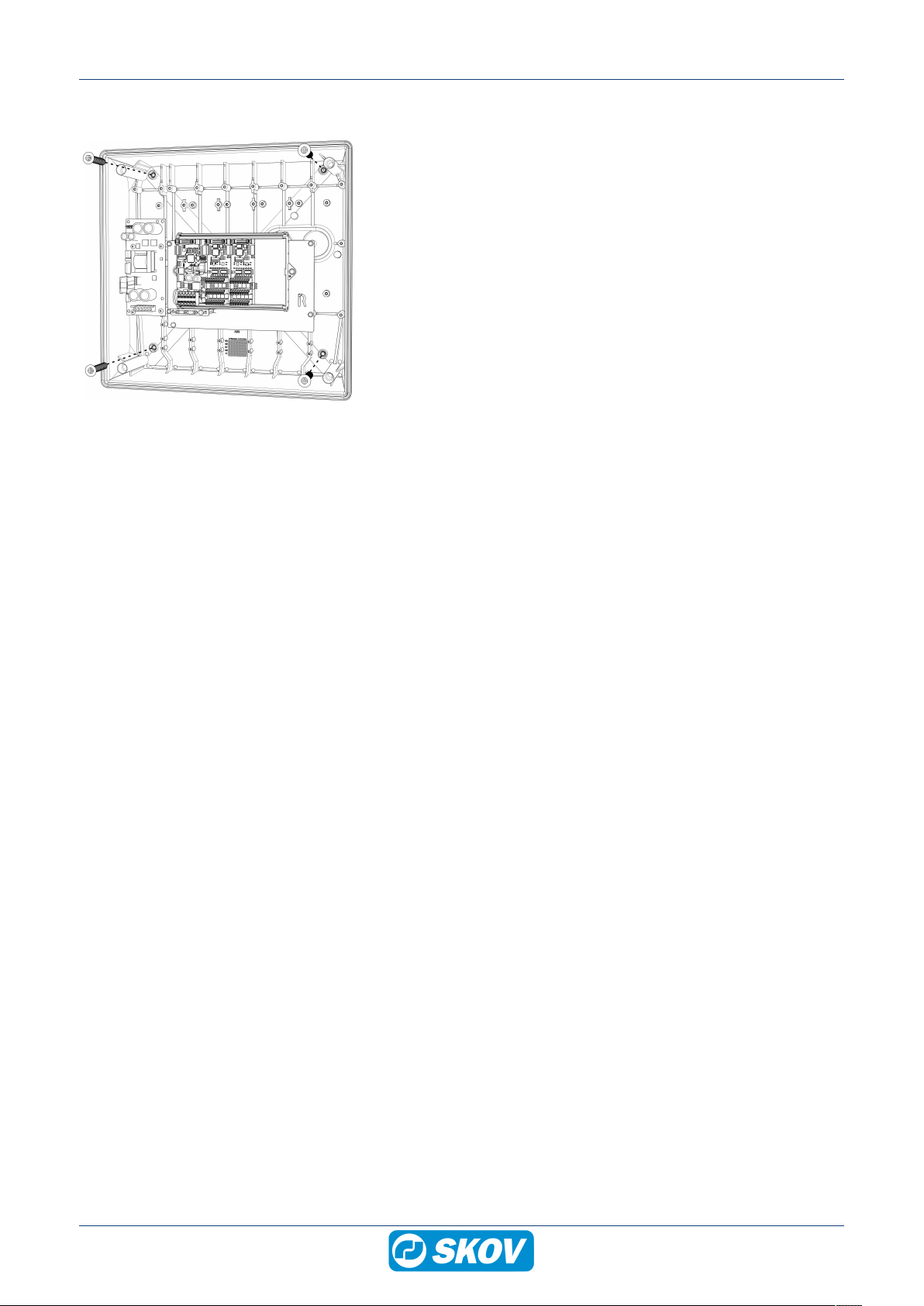
3.2 Mounting on wall .......................................................................................................................... 8
4 Installation guide ............................................................................................................................................9
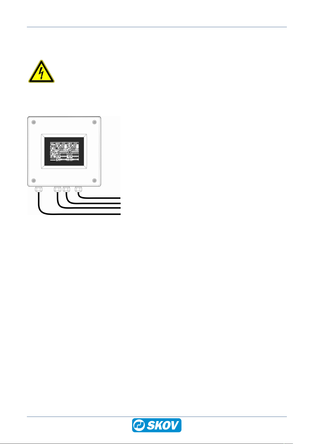
4.1 Electrical connection .................................................................................................................... 9
4.2 Cable routing................................................................................................................................ 9
4.3 Nano CAN bus coupler .............................................................................................................. 10
4.3.1 LED indication on the CAN bus coupler..................................................................................... 11
4.4 Nano I/O module digital ............................................................................................................. 12
4.5 Connection in DOL 100.............................................................................................................. 13
4.6 Setting up the DOL 100 in the controller.................................................................................... 14
4.7 Cable Plan ................................................................................................................................. 15
4.8 Circuit diagram........................................................................................................................... 16
4.8.1 DOL 100 and water meter.......................................................................................................... 16
4.8.2 DOL 100 and DOL 192 12 ......................................................................................................... 16
4.8.3 DOL 100 and DOL 192 20 ......................................................................................................... 17
4.8.4 DOL 100 and DOL 192 30-75 .................................................................................................... 17
4.8.5 DOL 100 and capacitive sensor................................................................................................. 18
5 Cleaning ........................................................................................................................................................19
6 Troubleshooting guide.................................................................................................................................20
7 Technical data...............................................................................................................................................21

DOL 100 Digital Box
Technical User Guide 5
1 Product description
DOL 100 digital 8I/16I/24I/32I box is used to connect water meter, egg counter, and capacitive sensor to the
CAN bus communication and thereby avoid numerous cables to the climate controller.
The DOL 100 converts the signal into digital signals and transmits them to the controller using CAN bus commu-
nication.
• DA 100 digital is available in four variants:
• Connect up to 8 items to the DOL 100 digital 8I box.
• Connect up to 16 items to the DOL 100 digital 16l box.
• Connect up to 24 items to the DOL 100 digital 24I box.
• Connect up to 32 items to the DOL 100 digital 32I box.
(C)
(B) (A)
(D)
(E)
(A) Controller
(B) Connect up to 32 items to the DOL 100
digital 8I/16I/24I/32I box.
(C) Water meter
(D) Egg counter
(E) Capacitive sensor

DOL 100 Digital Box
6 Technical User Guide
2 Product survey
130183 DOL 100 digital 8l box
130184 DOL 100 digital 16l box
130191 DOL 100 digital 24l box
130192 DOL 100 digital 32l box
External I/O box for connection of water meter, egg counter or capacitive
sensor.
The DOL 100 converts the signal into digital signals and transmits them to
the controller using CAN bus communication.
Standard software / hardware of the DOL 530/630 series supports 13 I/O
modules in total. DOL 100 counts as one module.
0-24 V inputs terminals: 8, 16, 24 or 32.
Is used with the CAN bus module (132245) and a CAN bus cable
(130121-130128).
2.1 Accessories
132245 CAN bus module
Always use the CAN bus module when using external CAN bus communi-
cation.
One for each controller.
130121 CAN bus cable 50 m
130125 CAN bus cable 100 m
130126 CAN bus cable 250 m
130122 CAN bus cable 500 m
For indoor use.
Must be used with external units using CAN bus communication.
130123 CAN bus cable UV 50 m
130127 CAN bus cable UV 100 m
130128 CAN bus cable UV 250 m
130124 CAN bus cable UV 500 m
For outdoor use.
Must be used with external units using CAN bus communication.

DOL 100 Digital Box
Technical User Guide 7
3 Mounting guide
3.1 Recommended tools
Below follows a list of tools recommended for installation of the DOL 100.
Item Description
Cordless drill
Screwdriver bits
Utility knife
Multimeter
Tape measure
Side cutter
Pointed pliers
Ladder
Screwdriver
Spirit level

DOL 100 Digital Box
8 Technical User Guide
3.2 Mounting on wall
Mount the DOL 100 digital box on the wall us-
ing four screws.

DOL 100 Digital Box
Technical User Guide 9
4 Installation guide
4.1 Electrical connection
Installation, servicing and troubleshooting of all electrical equipment must be carried out by quali-
fied personnel in compliance with the applicable national and international standard EN 60204-1
and any other EU standards that are applicable in Europe.
The installation of a power supply isolator is needed for each motor and power supply to facilitate
voltage-free work on the electrical equipment. The power supply isolator is not included.
4.2 Cable routing
To prevent water from running into the DOL
100 via cables and screwed connections, run
the cables so that water does not gather around
the cable in the gasket of the screwed connec-
tion.

DOL 100 Digital Box
10 Technical User Guide
4.3 Nano CAN bus coupler
(A)
(A) (A)
(A)
(B)
(D)
(C)
(E)
Item Function Description
(A) Terminals Terminals to I/O modules
(B) N1 GND
N2 +24V
N3 CAN_H
N4 CAN_L
N5 SHIELD
N6 CAN GND
0 V
Power supply +24 VDC (max. 2.1 A)
CAN high (brown CAN bus)
CAN low (white CAN bus)
Shield (braided shield CAN bus)
(green CAN bus)
The terminal can also be used as a looped terminal strip to the next box.
(C) CAN ID CAN bus address (CAN ID). The address switches are used for setting the CAN ID.
The DOL 100 must have a specific CAN ID for the controller to communicate with it. The
address of the individual DOL 100 corresponds to the address in the controller in the
menu Technical | Setup | Installation | I/O Modules | Additional I/O Modules
The address switches
X10 is set to 5 in connection with DOL 100 water and 3 in connection with DOL 100 digi-
tal.
The address switches X01 are set to the displayed number or letter after the figure 5
or 3 in the controller. If change of address, restart DOL 100 for the change to take effect.
(D) TERM ON
Jumper is set to (ON).
(E) TERM ON CAN bus termination. If DOL 100 is the last node in the CAN bus communication, the
jumper must be set to (ON) .

DOL 100 Digital Box
Technical User Guide 11
4.3.1 LED indication on the CAN bus coupler
(A)
(B) (D)
(C)
(D)
Item Function LED color Description
(A)
24 V IN
Green
ON: 24 V DC power supply OK.
24 V Log ON: 24 V DC Internal OK.
24 V I/O ON: 24 V DC I/O fuse F1 OK.
(B)
Internal CAN bus RX Green ON: receiving data
Internal CAN bus TX Red ON: transmitting data
(C)
External CAN bus
RX
Green ON: receiving data
External CAN bus
TX
Red ON: transmitting data
(D)
CPU RUN Green FLASHES: OK.
OFF: not ready for operation.
Operate Yellow States the CAN bus status
ON: operate
OFF: pre-operate
CAN ERROR Red OFF: CAN bus OK.
FLASHES: CAN bus error.
ERROR Red General error
Boot mode All LED ON (CPU RUN, Operate, CAN ER-
ROR and ERROR

DOL 100 Digital Box
12 Technical User Guide
4.4 Nano I/O module digital
Nano I/O module # 1
(A)
Nano I/O module # 2
(A)
(B)
(G)
(F)
(E)
(C)
(D)
Nano I/O module # 3 Nano I/O module # 4
(A) (A)
(A)
(B)
(G)
(F)
(C)
(D)
(E)
(C)
(D)
(E)
(C)
(D)
(E)
Item Function Description
(A) TERM CAN bus termination.
The jumper is mounted on the I/O module furthest away from the CAN bus coupler.
(B) CAN ID Jumper setting on I/O module # 1.
Jumper setting on I/O module # 2.
Jumper setting on I/O module # 3.
Jumper setting on I/O module # 4.
(C) Terminals +24 V DC N11 -N28. Max. 1.9 A gathered on the outputs N11-N28
(D) Terminals Signal input N11 -N28
(E) Terminals GND N11 -N28
(F) High / Low
Jumper Low (NPN)
(G) LED 1-8 Green = Input 1-8 active

DOL 100 Digital Box
Technical User Guide 13
4.5 Connection in DOL 100
24 V DC power supply
CAN bus connection, see dimensions below.
CAN_H = brown
CAN_L = white
CAN GND = green.
Strip the cable so the shield can be connected to the DOL
100 when mounting in the connection terminal.
As illustrated by the picture, the connection terminal can
also be used as a looped terminal strip to the next box.

DOL 100 Digital Box
14 Technical User Guide
4.6 Setting up the DOL 100 in the controller
Make sure the CAN protocol is set to CANopen.
Technical | Setup | Installation | I/O Modules | CAN protocol
Select number of DOL 100.
The DOL 100 8I box supports up to 8 water meters, egg counters or
capacitive sensor.
The DOL 100 16I box supports up to 16 water meters, egg counters or
capacitive sensor.
The DOL 100 24I box supports up to 24 water meters, egg counters or
capacitive sensor.
The DOL 100 32I box supports up to 32 water meters, egg counters or
capacitive sensor.
The software supports up to 13 I/O modules. DOL 100 is counted in as
one module.
Technical | Setup | Installation | I/O Modules | Extra I/O modules
Here you see the CAN bus address (CAN ID) and if it is connected.
Select number of water meters
Technical | Setup | Installation | Production | Water meter
Select number of egg counters meters
Technical | Setup | Installation | Production | Egg counter | Egg
counters installed

DOL 100 Digital Box
Technical User Guide 15
The DOL 539/535 installation menu specifies which connection termi-
nal numbers and in which DOL 100 box the water meters must be con-
nected.
For correct connection of the items, see menu Technical | Setup |
Show connections
I/O#1 N13 = DOL 100 box no. 1, connection terminal N13.
I/O#3 N28 = DOL 100 box no. 3, connection terminal N28.
4.7 Cable Plan
Power supply
Power supply
CAN bus cable
max. 400 m
(D) (A)
(B)
(C)
(E)
(F)
(G)
(A) Power supply to the controller two-wire cable including earthing contact.
(B) Max. 400 m CAN bus communication cable between the DOL 100 digital 8l/16l box and the controller. The
CAN bus cable connecting all units of the system may not exceed 400 m.
(C) Power supply to the DOL 100 digital 8I/16I/24I/32I box, two-wire + earthing contact.
(D) Two-wire control cable to the water meter.
(E) Three-wire power supply and control cable to DOL 192 12-20 egg counter.
(F) Two-wire control cable to DOL 192 30-75 egg counter.
(G) Four-wire power supply and control cable to capacitive sensor.

DOL 100 Digital Box
16 Technical User Guide
4.8 Circuit diagram
4.8.1 DOL 100 and water meter
Water
meter
Water
meter
Water
meter
Water
meter
External digital box
4.8.2 DOL 100 and DOL 192 12
External digital box
Egg counter
12 cm
Egg counter
12 cm
Egg counter
12 cm
Egg counter
12 cm

DOL 100 Digital Box
Technical User Guide 17
4.8.3 DOL 100 and DOL 192 20
Egg counter
20 cm
Egg counter
20 cm
Egg counter
20 cm
Egg counter
20 cm
External digital box
4.8.4 DOL 100 and DOL 192 30-75
Egg counter
30-75 cm
Egg counter
30-75 cm
Egg counter
30-75 cm
Egg counter
30-75 cm
External digital box

DOL 100 Digital Box
18 Technical User Guide
4.8.5 DOL 100 and capacitive sensor
External digital box

DOL 100 Digital Box
Technical User Guide 19
5 Cleaning
The DOL 100 box is maintenance-free but should be kept free of litter and dirt.
Clean the product with a cloth that has been wrung out almost dry in water and avoid using:
• high-pressure cleaner
• solvents
• corrosive/caustic agents

DOL 100 Digital Box
20 Technical User Guide
6 Troubleshooting guide
Defects
No light LED on the CAN bus cou-
pler.
Check the 24 V DC power supply to the DOL 100.
Check that you have installed the DOL 100 digital 8I/16I/24I/32I box and
water meter/egg counter/capacitive sensor in the controller, see section
Setting up the DOL 100 in the controller [}14]
No CAN bus communication con-
nectivity with the DOL 100 digital
8l/16l box.
Check resistance between CAN H and CAN L; the resistance must be
approximately 60 ohms.
If the resistance is > 100 ohms, a termination is missing.
If the resistance is < 45 ohms, there are too many terminations.
Other manuals for DOL 100
2
Table of contents
Other Skov Media Converter manuals
Popular Media Converter manuals by other brands

Sonos
Sonos Multi-Room Music System user guide

Quark-Elec
Quark-Elec QK-A036 manual

KYLAND
KYLAND KOM300F Hardware installation manual

StarTech.com
StarTech.com ST122LEA instruction manual

B&B Electronics
B&B Electronics MES1A quick start guide

Schnick-Schnack-Systems
Schnick-Schnack-Systems DPB Pixel-Router Pro user guide