Skov DOL 38-2 Manual

DOL 38-2 Frequency
Converter
Technical User Guide
604277 • 2022-07-01
English For other language variants of this document we refer to:
Español Para otras variantes del idioma de este documento, visite:
Français Pour les versions dans d'autres langues de ce document veuillez consulter:
http://docs.skov.com/1159


DOL 38-2 Frequency Converter
Technical User Guide 3
Product and Documentation Changes
SKOV A/S reserves the right to change this document and the product herein described without further notice.
In case of doubt, please contact SKOV A/S.
The date of change appears from the front and back pages.
IMPORTANT
Notes concerning alarm systems
Breakdowns, malfunctions or faulty settings may cause substantial damage and financial losses when regulat-
ing and controlling the climate in a livestock house. It is therefore essential to install a separate, independent
alarm system that monitors the house climate concurrently with the climate and production controller. According
to EU-directive No. 98/58/EU, an alarm system must be installed in all mechanically ventilated houses.
We would like to draw your attention to the fact that the product liability clause of general terms and conditions
of sale and delivery specifies that an alarm system must be installed.
Note
• All rights belong to SKOV A/S. No part of this manual may be reproduced in any manner whatsoever without
the expressed written permission of SKOV A/S in each case.
• All reasonable efforts have been made to ensure the accuracy of the information contained in this manual.
Should any mistakes or imprecise information occur in spite of this, SKOV A/S would appreciate being noti-
fied thereof.
• Irrespective of the above, SKOV A/S shall not accept any liability with regard to loss or damage caused or
alleged to be caused by reliance on any information contained herein.
• Copyright by SKOV A/S.

DOL 38-2 Frequency Converter
Technical User Guide
1 Product description ....................................................................................................................................... 5
2 Product survey ............................................................................................................................................... 6
3 Mounting guide............................................................................................................................................... 7
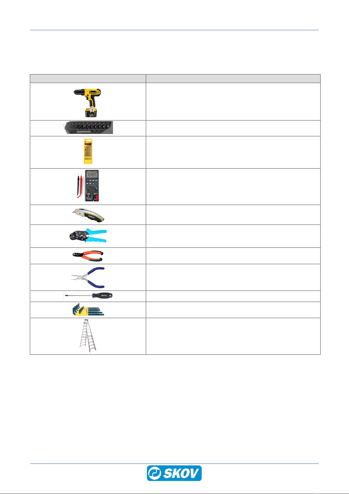
3.1 Recommended tools.................................................................................................................. 7
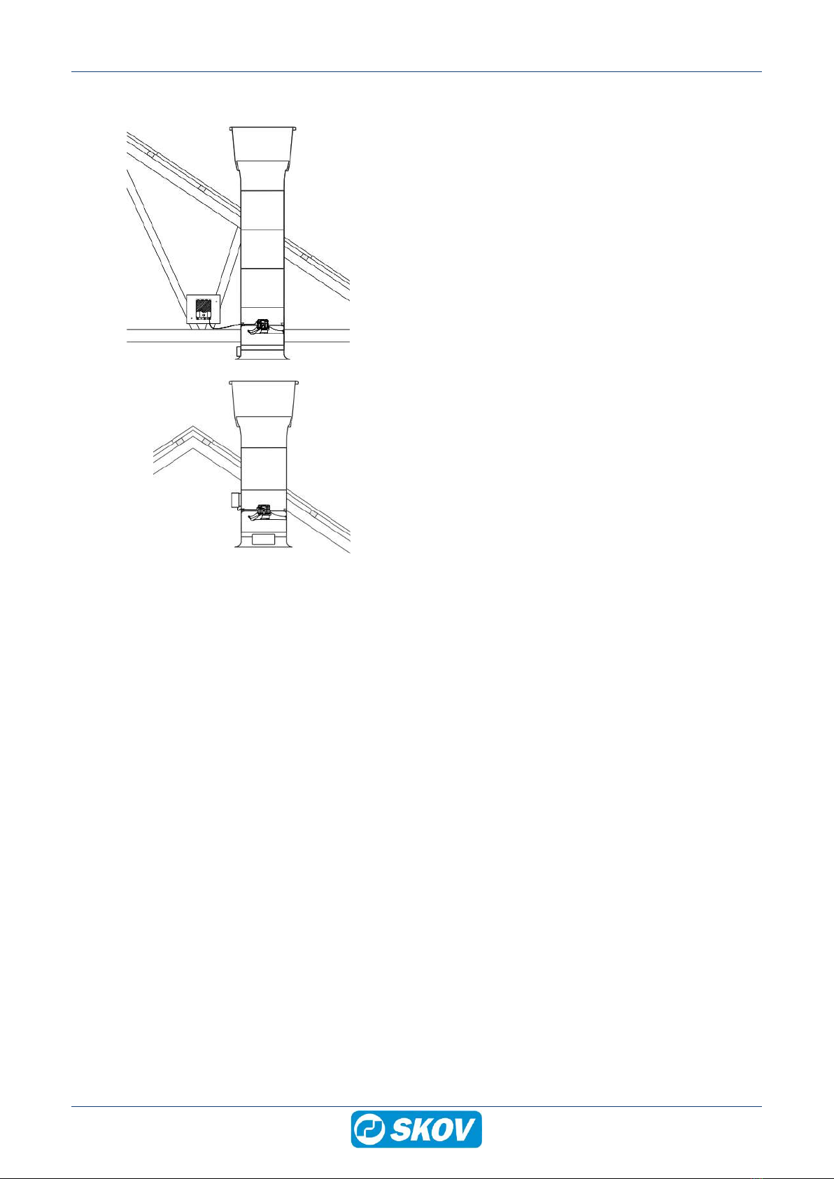
3.2 Position of motor controller/frequency converter .................................................................. 8
3.3 Mounting distances for the motor controller/frequency converter....................................... 8
3.4 Position of motor controller/frequency converter .................................................................. 9
4 Installation guide.......................................................................................................................................... 10
4.1 Electrical connection............................................................................................................... 10
4.1.1 Disclaimer at retrofitting fans ..................................................................................................... 10
4.1.2 Mains supply dimensioning regarding harmonic distortion ........................................................ 10
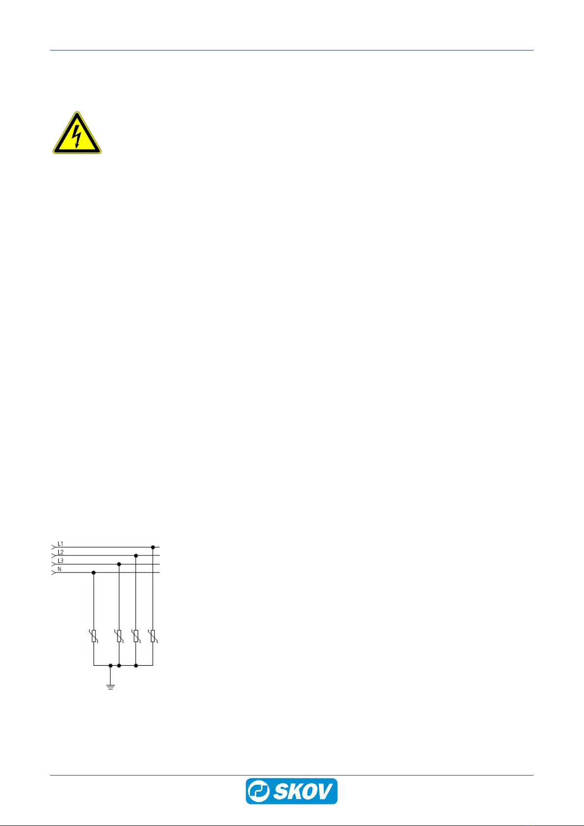
4.1.3 Overvoltage protection............................................................................................................... 10
4.1.4 Cabling in the exhaust unit......................................................................................................... 11
4.1.5 Cabling into the motor controller/frequency converter ............................................................... 11
4.2 Connection in the LPC motor controller/frequency converter ............................................ 12
4.2.1 Terminals for power supply........................................................................................................ 13
4.2.2 Terminals for supply of the fan motor ........................................................................................ 13
4.2.3 Signal terminals ......................................................................................................................... 14
4.2.4 Terminals on relay module......................................................................................................... 14
4.3 LED indication on the motor controller/frequency converter.............................................. 15
4.4 Alarms....................................................................................................................................... 15
4.5 Adjusting the jumper and connecting the shutter................................................................ 16
4.6 General information about circuit diagrams ......................................................................... 17
4.6.1 Color code.................................................................................................................................. 17
4.6.2 Power supply isolator................................................................................................................. 17
4.6.3 Letter code ................................................................................................................................. 17
4.7 Cable plans and circuit diagrams........................................................................................... 18
4.7.1 DOL 38-2 with fan ...................................................................................................................... 18
4.7.1.1 Cable plan.................................................................................................................................. 18
4.7.1.2 Circuit diagram........................................................................................................................... 19
4.7.2 DOL 38-2 with DA 74CV and DA 600 fan .................................................................................. 20
4.7.2.1 Cable plan.................................................................................................................................. 20
4.7.2.2 Terminals in DA 74CV ............................................................................................................... 20
4.7.2.3 Circuit diagram........................................................................................................................... 21
4.7.2.4 Circuit diagram - thermal cutout................................................................................................. 22
4.7.3 DOL 38-2 and DA 600 fan with reverse ..................................................................................... 23
4.7.3.1 Cable plan.................................................................................................................................. 23
4.7.3.2 Circuit diagram........................................................................................................................... 24
4.7.4 DOL 38-2 and DA 600 fan with alarm ........................................................................................ 25
4.7.4.1 Cable plan.................................................................................................................................. 25
4.7.4.2 Circuit diagram........................................................................................................................... 26
5 Maintenance instructions ............................................................................................................................ 27
5.1 Cleaning.................................................................................................................................... 27
5.1.1 Fan............................................................................................................................................. 27
5.1.2 Motor controller/frequency converter ......................................................................................... 27
5.2 Recycling/Disposal .................................................................................................................. 27
6 Troubleshooting guide ................................................................................................................................ 28
7 Technical data .............................................................................................................................................. 30
7.1 Dimensioned sketch ................................................................................................................ 31

DOL 38-2 Frequency Converter
Technical User Guide 5
1 Product description
DOL 38-2 is a sturdy frequency converter for three-phase fans.
DOL 38-2 is controlled by a 10--0 V signal from a climate controller.

DOL 38-2 Frequency Converter
6 Technical User Guide
2 Product survey
110451 DOL 38-2 VFD 4.5A 230V1 50/60Hz
Frequency converter is used for regulating three-phase fans.
The frequency converter is controlled via a 10-0 V signal.
The distance between the frequency converter and fan should not exceed 5
m (shielded cable).
409145 Thermal protection for fan 230 V with alarm contact
For the protection of a DA 600 fan with thermal cutout.

DOL 38-2 Frequency Converter
Technical User Guide 7
3 Mounting guide
3.1 Recommended tools
A list of the recommended tools for mounting purposes can be seen below.
Item Description
Cordless drill
Screwdriver bits
Drill kit
Multimeter
Utility knife
Cable clip pliers
Side cutter
Pointed pliers
Screwdriver
Allen key kit
Ladder

DOL 38-2 Frequency Converter
8 Technical User Guide
3.2 Position of motor controller/frequency converter
Motor controller/frequency converter must not be built-in
or covered and must be mounted on a solid, level sur-
face.
In order to uphold protection classifications, access and
cooling, the motor controller/frequency converter must
be positioned as shown in section Mounting distances
for the motor controller/frequency converter [}8].
3.3 Mounting distances for the motor controller/frequency converter
In order to ensure access of cables and cooling of the
motor controller/frequency converter, the distances to
the surroundings must be met.

DOL 38-2 Frequency Converter
Technical User Guide 9
3.4 Position of motor controller/frequency converter
The motor controller/frequency converter is positioned
so that the ambient temperature is between ÷ 40 °C and
+ 50 °C.
Mount the motor controller/frequency converter as close
to the fan as possible.
The 2 m cable included must not be extended.
However, for fan 1x230 V, a motor cable on 5 m can be
ordered if the 2 m is not sufficient.
The controller/frequency converter can be mounted on a
wooden plate fastened to a rafter on the ceiling or di-
rectly on the chimney.

DOL 38-2 Frequency Converter
10 Technical User Guide
4 Installation guide
4.1 Electrical connection
Installation, servicing and troubleshooting of all electrical equipment must be carried out by quali-
fied personnel in compliance with the applicable national and international standard EN 60204-1
and any other EU standards that are applicable in Europe.
The installation of a power supply isolator is required for each motor and power supply to facilitate
voltage-free work on the electrical equipment. The power supply isolator is not included.
4.1.1 Disclaimer at retrofitting fans
In the case of retrofitting fans in an existing house, regardless of ON/OFF fans, LPC fans or frequency convert-
ers SKOV recommends that a local expert is involved in checking the electrical installations. The focus should
be on cable dimensions, overload protections, local transformers, etc. It is of outmost importance to take the fan
specifications into account and, at the same time, ensure that local requirements are fulfilled.
4.1.2 Mains supply dimensioning regarding harmonic distortion
LPC motor controllers and frequency converters function like any other electronic power converter by converting
AC to DC. As this conversion produces a non-sinusoidal current, the mains supply for the controller is affected
by harmonic distortion.
The electrician or the user of the equipment must ensure, possibly through contact with the supply company,
that the equipment is connected to a properly sized mains supply.
4.1.3 Overvoltage protection
SKOV A/S equipment are protected for high level of surge transient, but in some cases, specially in areas with
frequent lightning strikes and power outage, additional protection is necessary. To reduce the risk of damaging
the electronic equipment by large surge overvoltage, it is therefore recommended, always to install Surge Pro-
tection Devices (SPD) in the mains supply.
As a minimum a Type 2/Class II device should be installed in each livestock house wiring box. A device of
8/20us - 40kA/phase or higher is recommended.
In areas with a high amount of surge overvoltage a Type 1/Class I device is reccomended to be installed at the
transformer/ATS as the first protection device, together with Type 2 in each livestock house wiring box as sec-
ond protection device. A Type 1 device of 10/350us - 25kA/phase or higher is are recommended.
Local electrical engineers must be consulted for correct dimensioning and installation of the SPD device.
Figure1: Example of installation of SPD

DOL 38-2 Frequency Converter
Technical User Guide 11
4.1.4 Cabling in the exhaust unit
Drill a hole in the exhaust unit duct for the fan cable and
pull it along a support to the same side as the motor con-
troller/frequency converter.
4.1.5 Cabling into the motor controller/frequency converter
In order to prevent water from running into the motor
controller/frequency converter via cables and screwed
connections, the cabling must be carried out so that it
can stand water around the cable in the gasket of the
screwed connection.

DOL 38-2 Frequency Converter
12 Technical User Guide
4.2 Connection in the LPC motor controller/frequency converter
1Motor connection terminals (U, V, W, PE)
2Connection terminals for braking resistor (not used)
3Connector for optional module
4Terminal block for programming interface
5RJ12 programming connector (2 x slave / 1 x master)
63-point strain relief for modbus cable
7Power supply terminals for 1-phase (L, N, PE) and 3-phase (L1, L2, L3, N, PE)

DOL 38-2 Frequency Converter
Technical User Guide 13
4.2.1 Terminals for power supply
Supply 1x230 V.
4.2.2 Terminals for supply of the fan motor
Remember to strip the cable so that the protective shield
from the fan can be connected to the motor controller
during mounting under the rail.
Connection from motor controller to fan motor.

DOL 38-2 Frequency Converter
14 Technical User Guide
4.2.3 Signal terminals
Not in use
Not in use
Ground
10 V output supply (max. 100 mA)
Signal from climate computer or potentiometer
Ground
(1) 10-0 V = GND (Jumper between terminal 7 and GND)
(2) 0-10 V = open
(3) Normal = open
(4) Reverse = GND (Jumper between terminal 8 and GND)
Ground
Not in use
Max. 4 mm2
Max. 2.5 mm2
8-15 mm
(1) 10 V = 0 % speed
0 V = 100 % speed
(2) 10 V = 100 % speed
0 V = 0 % speed
(3) Counterclockwise rotation (CCW)
(4) Clockwise rotation (CW)
4.2.4 Terminals on relay module
Alarm NO
Max. 30 V DC / 24 V AC
Alarm NC

DOL 38-2 Frequency Converter
Technical User Guide 15
4.3 LED indication on the motor controller/frequency converter
The motor controller/frequency converter is equipped
with a two-color LED for indication of different operating
modes.
LED is located on the underside next to the cable
glands.
• Constantly green when mains voltage is connected.
• Constantly red in case of at least one critical alarm.
• Flashes red in case of at least one non-critical alarm.
4.4 Alarms
The motor controller/frequency converter including relay module provides alarm monitoring which monitors the
optimal and flawless operation and generates an alarm if operating or performance problems are observed.
Alarms are divided into "critical" alarms and "non-critical" alarms.
“Critical" alarms stop the motor controller/frequency converter/motor, LED emits red light and the alarm relay is
activated.
“Non-critical" alarms reduce the performance of the motor controller/frequency converter/motor, and the LED
flashes red.
The built-in alarm monitoring stops the motor controller/frequency converter/motor.
The alarm automatically resets, if the error ceases, and motor controller/frequency converter/motor starts.
Reset the alarm, if the maximum number of restarts (5 x/60 min) is exceeded.
Disconnect the mains voltage for more than 60 sec and the alarm will automatically be reset.
Alarm overview
Error Alarm priority Motor controller/frequency
converter/motor
Error Alarm priority
Supply voltage too high
Critical Stopped after 5 restart at-
tempts caused by the same
error within 60 minutes
Emits red
light
Enabled
Current consumption of the mo-
tor too high
Phase errors; one or more
phases interrupted (L1, L2, L3)
Obstructed impeller
Wrong direction of rotation
Phase error on the motor supply
(U, V, W)
Internal communication error
Supply voltage too low
Non-critical Reduced performance Flashes red Not activated
Internal temperature of motor
controller too high.
(>95 °C)
Motor current has reached its
limit value
Error in internal EEPROM circuit
Ripple voltage too high

DOL 38-2 Frequency Converter
16 Technical User Guide
Alarm overview
External 24V DC supply over-
loaded
Supply voltage too high
4.5 Adjusting the jumper and connecting the shutter
Set the jumper on the PCB to give actuator the desired
function.
LED indication
OK = slow flashing
Error = quick flashing (10 times/second)
H1 Actuator controller or +24 V DC supply
H2 Actuator controller
H3 0 V
H6 +24 V DC supply
H7 0-10 V position feedback
H8 0 V
H9 Open collector (transistor output) is used for fan with motor
controller.
H10/11a and H12a relay output is used for fan without motor
controller.

DOL 38-2 Frequency Converter
Technical User Guide 17
4.6 General information about circuit diagrams
Symbols are in accordance with the IEC/EN 60617 standard.
The classification of the symbols ("letter codes") on the symbols is in accordance with the IEC/EN 81346-2 stan-
dard.
Reference designations are in accordance with IEC/EN 81346-1:2001 structuring principles and reference des-
ignations. This standard indicates structured methods for naming electrotechnical systems.
4.6.1 Color code
Letter Code Color Standard
BK Black
Color coding on wires are in accor-
dance with standard IEC 60757:
Letter codes to identify colors used
on drawings, diagrams, labelling,
etc.:
BN Brown
RD Red
OG Orange
YE Yellow
GN Green
BU Blue (incl. light blue)
VT Violet (purple red)
GY Grey (slate)
WH White
PK Pink
GD Gold
TQ Turquoise
SR Silver
GNYE Green-and-yellow
4.6.2 Power supply isolator
Power supply isolator
The installation of a power supply isolator is required for each motor and
motor control.
4.6.3 Letter code
The letter codes used in accordance with standard IEC/EN61346-2.
-F -K -M -Q -S -T -W
Protective equipment RCCB /
Initial fuse Protective motor
switch
Controller
Contactor
Fan
Motor
Power supply
isolator
Switch Motor con-
troller
Cable

DOL 38-2 Frequency Converter
18 Technical User Guide
4.7 Cable plans and circuit diagrams
4.7.1 DOL 38-2 with fan
4.7.1.1 Cable plan

DOL 38-2 Frequency Converter
Technical User Guide 19
4.7.1.2 Circuit diagram
Example of terminal number
For correct connection
see the setup menu
Show connection in the controller
Frequency converter
Fan

DOL 38-2 Frequency Converter
20 Technical User Guide
4.7.2 DOL 38-2 with DA 74CV and DA 600 fan
4.7.2.1 Cable plan
4.7.2.2 Terminals in DA 74CV
This manual suits for next models
1
Table of contents
Other Skov Media Converter manuals