Skutt KilnLink User manual

WWW.SKUTT.COM
6441 SE JOHNSON CREEK BLVD. PORTLAND, OR 97206 (503) 774-6000 SKUTT@SKUTT.COM
Rev. 1/15/18
KilnLink
Installation Manual

Specifications
Provided by Skutt with purchase of Skutt KilnMaster kiln with LinkBoard and KilnLink
• 1 KilnLink Box for every 4 kilns.
• 1 KilnLink Power Supply 110-120V, 50-60HZ, 0.15A
• 1 LinkBoard per Kiln (installed at factory when ordered with new kiln)
• Current Sensor (standard on newer KM kiln models)
• 1 Phone Jack with 3-way splitter (for use with multiple kiln installation)
• 2 - 14 ft. RJ11 Cable (Straight through*) - Kiln to KilnLink Box connection
• Current firmware in controller. Guaranteed with purchase of kiln manufactured after
7/19/2012.
*This looks likes a standard phone cord, but it is different. Use only cords supplied by Skutt.
Required by Customer for Installation
• Internet Connection (always on)
• 1 Ethernet Network Cable (sufficient length to connect KilnLink Box to internet.
• 120V Power Outlet within 6 ft of KilnLink Box location.
• KilnMaster Kiln controller with current firmware. Guaranteed with purchase of kiln
manufactured after 7/19/2012. (Controller must be replaced or upgraded if muanu-
factured prior to this date.)
Required by Customer for Operation - One or more of the following
• 1 Computer with Internet connection. Mac, PC or Unix/Linux.
• Cell phone plan with text (SMS) plan. (If text alerts are to be utilized. Unlimited text
plan recommended.)
• 1 Smart Phone. IOS, Android, or Blackberry (tested) if mobile web app is to be used.
2KL

3
Installation Instructions
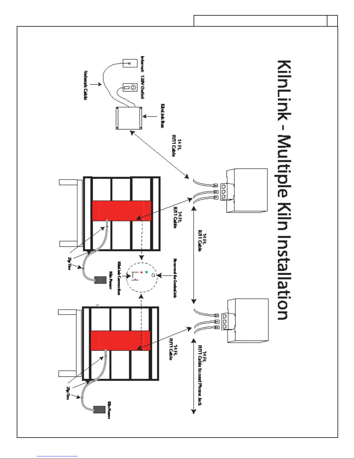
We recommend setting up your KilnLink system using the provided phone jack with
3-way splitter (as shown in Multiple Kiln Installation diagram on page 7), even if you are in-
stalling a system for just one kiln. This way, most of the components are in place if you want
to connect more kilns.
1. Locate the KilnLink Box at a convenient location that will remain dry on a wall near
the kiln so that either; a 14 ft. cable will reach between the KilnLink Box and the
control box on the kiln, or so that the KilnLink Box is within a 14 ft. cable reach of a
3-way splitter and the 3-way spliter is within a 14 ft. cable reach of the control box on
the kiln. The KilnLink Box will also need to be within 320 ft. of an Internet connec-
tion and within 6 ft. of a 120 volt power outlet. Be sure the intended routing of any
cables or power cords will prevent them from lying against the (hot) sides or lid of
the kiln(s). Mount the KilnLink Box to the wall using mounting screws or anchors ap-
propriate for the type of wall material.
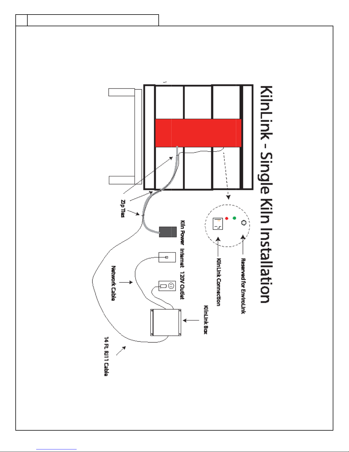
2. Plug one end of an Ethernet Network Cable (not provided) of appropriate length
(with RJ45 connectors) into an Internet connection and plug the other end of the
cable into the KilnLink Box.
3. Mount the phone jack with 3-way splitter to the wall using the double stick tape pad
or screws (located inside the jack cover) so that it is within a 14 ft. cable reach of the
control box on the kiln. Note: For multiple kiln connections, each phone jack with
3-way splitter will need to be within a 14 ft. cable reach of the next phone jack with
3-way splitter.
4. Plug one end of a 14 ft. RJ11 cable (included with the LinkBoard kit) into the KilnLink
Box and plug the other end into the far left position of the 3-way splitter.
5. Using the second 14 ft. RJ11 cable (included with the LinkBoard kit), plug one end
into the center position of the 3-way splitter and plug the other end into the Link-
Board receptacle on the kiln control box. This cable can be tied to the kiln’s power
cord with zip ties if desired.
6. If connecting multiple kilns, use another 14 ft. RJ11 cable (included with additional
kiln LinkBoard kit) and plug one end into the far right position of the previous kiln’s
3-way splitter and plug the other end into the far left position of the 3-way splitter
being used for additonal kiln. See illustration on page 7 for multiple kiln installation.
7. Plug in the KilnLink Power Supply to the building’s 120 volt power outlet and plug
the other end of the cable from the Power Supply into the KilnLink Box.
KL

4
Setting the ID
If you are connecting more than one kiln to your KilnLink Box (you can connect up to
four), you will need to have a unique ID for each kiln. All new kilns will leave the factory with
a Kiln ID set to “1”. If you are only installing 1 kiln, you may skip this step. To set the ID for
each additional kiln, follow these instructions:
• From Idle press MENU until you see “CNFG” and press ENTER.
• Press MENU until you see “Id” and press ENTER.
• The display will flash the kiln ID currently set for the kiln. Change it to “2” by press-
ing the “2” key and press ENTER.
• If there are 3 or 4 kilns, change these Id settings to 3 and 4 respectively.
Testing the Unit
There are red and green indicator lights on both the LinkBoard and KilnLink Box. These
are used for troubleshooting to make sure the two units are communicating correctly with
each other and the Internet. After 1 minute the light should perform as follows:
KilnLink Box
• Red - Solid with brief flashing once a minute.
• Green - Blink once every 2 seconds with intermittent bursts of rapid blinking when
communicating.
LinkBoard
• Red - Solid indicates good connection. No light often indicates you did not use
proper cable.
• Green - Off with intermittent bursts of rapid blinking when communicating.
If you have problems connecting, please contact Skutt’s Technical Support Department
for additional help troubleshooting.
4KL

5
NOTE: Before you can activate your account, you will need to provide your Distributor with
this completed form for each KilnLink box you have purchased.
MySkutt Activation Request Form
Kiln Information
Kiln 1 Kiln 2 Kiln 3 Kiln 4
Model _______ _______ _______ _______
Voltage _______ _______ _______ _______
Phase _______ _______ _______ _______
Serial Number _______ _______ _______ _______
KilnLink Box Information
Serial Number (Located on back of the KilnLink Box) ___________________
Distributor Information
Company Name _____________________________________________
City _________________________ State ______ Phone __________
FI Purchased My KilnLink Data Plan Directly From Skutt
Location Information
Company/School District ______________________________________
Address ___________________________________________________
City _________________________ State ______ Zip __________
Phone __________
Primary User (Administrator) Information
Name ____________________________________
Phone ___________________________________
Email ___________________________________
Email this form to kilnlink@skutt.com or fax it to (503) 774-7833.
You may also provide it to your distributor to forward on to Skutt.
5
KL

6
Activating KilnLink Data Plan
The Data Plan associated with each kiln begins the first time you login with the kiln connect-
ed to the KilnLink Box.
Once your KilnLink has been installed and all the indicator lights are flashing correctly, it is
time to login and activate your account. You should have received a temporary User Name
and Password when you received the KilnLink Box. If you did not, you will need to contact
your Skutt distributor and give them the following information:
• Serial Number (S/N) (located on the side of your KilnLink Box)
• Name
• Location
• Service Plan (1 Yr or 5 Yr)
They will then contact a KilnLink administrator to assign you a temporary User Name and
Password.
Each KilnLink Box requires its own User Name and Password, so if you have multiple KilnLink
Boxes, you will need to login to them independently.
Login Instructions
1. Go to www.myskutt.com
2. Input your temporary User Name and Password. If you are installing an additional unit to
an existing KilnLink Box you can login with your current User Name and Password.
3. Click on SUBMIT.
6KL

7
7
KL

8KL
Table of contents
Popular Measuring Instrument manuals by other brands

Newtons4th
Newtons4th PPA55 Series Startup guide

Schaller
Schaller humimeter PM3 user manual

EUTECH INSTRUMENTS
EUTECH INSTRUMENTS CYBERSCAN CON100200300 CONDUCTIVITY PORTABLE... Manuel d'instructions

Lumel
Lumel NA3 Service manual

TESTO
TESTO 310 instruction manual

Lubermate
Lubermate L-DOM34-01 instruction manual