SKY Agriculture Vision II DUO User manual

Notice Originale
Original Instructions
Originalbetriebsanleitung
A LIRE ATTENTIVEMENT AVANT D’UTILISER LE BOÎTIER
PLEASE READ CAREFULLY BEFORE USING THE CONTROL UNIT
VOR GEBRAUCH DES ELEKTRONIKGERÄTS SORGFÄLTIG LESEN
SKY Agriculture
La Conillais
44130 Saint Emilien de Blain
Tél :(33)02-40-87-11-24 · ou : (33)09-69-80-07-67
Site Internet : www.sky-agriculture.com
Réf: 400 610-01 FR-EN-DE / RFS
• Ces symboles sont utilisés dans cette notice chaque fois que des recommandations concernent votre sécurité, celle
d’autrui ou le bon fonctionnement de la machine.
• Transmettez impérativement ces recommandations à tout utilisateur de la machine.
Risque d’accident Risque d’endommager
la machine Faciliter le travail
Consignes de sécurité
Safety instructions
Sicherheitsvorschriften
Ne pas jeter le boîtier
•Follow the instructions contained in this manual.
•Follow the Seed drill User Manual recommendations.
•Never leave the driver’s position whilst the tractor is running.
•Carry out Seeddrill adjustments with the tractor stopped.
•Make sure no one is near the machine before calibrating the VISION DUO unit.
• These symbols are used in these instructions every time recommendations are provided concerning your safety, the
safety of others or the correct operation of the machine.
• These recommendations must be given to all users of the machine.
Risk of accident Risk of damage
to the machine Operating tip
•Die Anweisungen dieser Anleitung einhalten.
•Die Anweisungen des Benutzerhandbuchs der entsprechenden Drillmaschine einhalten.
•Den Führerstand niemals bei laufendem Schleppermotor verlassen.
•Einstellungen des Drillmaschine bei ausgestelltem Schlepper vornehmen.
•Darauf achten, dass sich beim Kalibrieren des VISION DUO niemand im Maschinenbereich aufhält.
• Diese Symbole werden in dieser Anleitung jedes Mal dann benutzt, wenn Empfehlungen für Ihre und anderer Per-
sonen Sicherheit oder den einwandfreien Betrieb der Maschine gegeben werden.
• Es ist unerlässlich, diese Empfehlungen an alle Benutzer der Maschine weiterzugeben.
Unfallgefahr Gefahr, die Maschine zu
beschädigen Arbeitserleichterung
•Respecter les instructions de cette notice.
•Respecter les instructions du manuel d’utilisation du semoir correspondant.
•Ne jamais quitter le poste de conduite lorsque le tracteur est en marche.
•Réaliser les réglages du Semoir tracteur à l’arrêt.
•Assurez-vous qu’il n’y ait personne autour de la machine avant d’eectuer l’étalonnage de la console VISION DUO.
Do not throw the
unit away
Elektronikgerät nicht
im Müll entsorgen
FR
EN
DE
2

Lire attentivement la notice avant l’utilisation. Comprendre son
boîtier électronique c’est mieux l’utiliser. En français suivre le symbole. FR
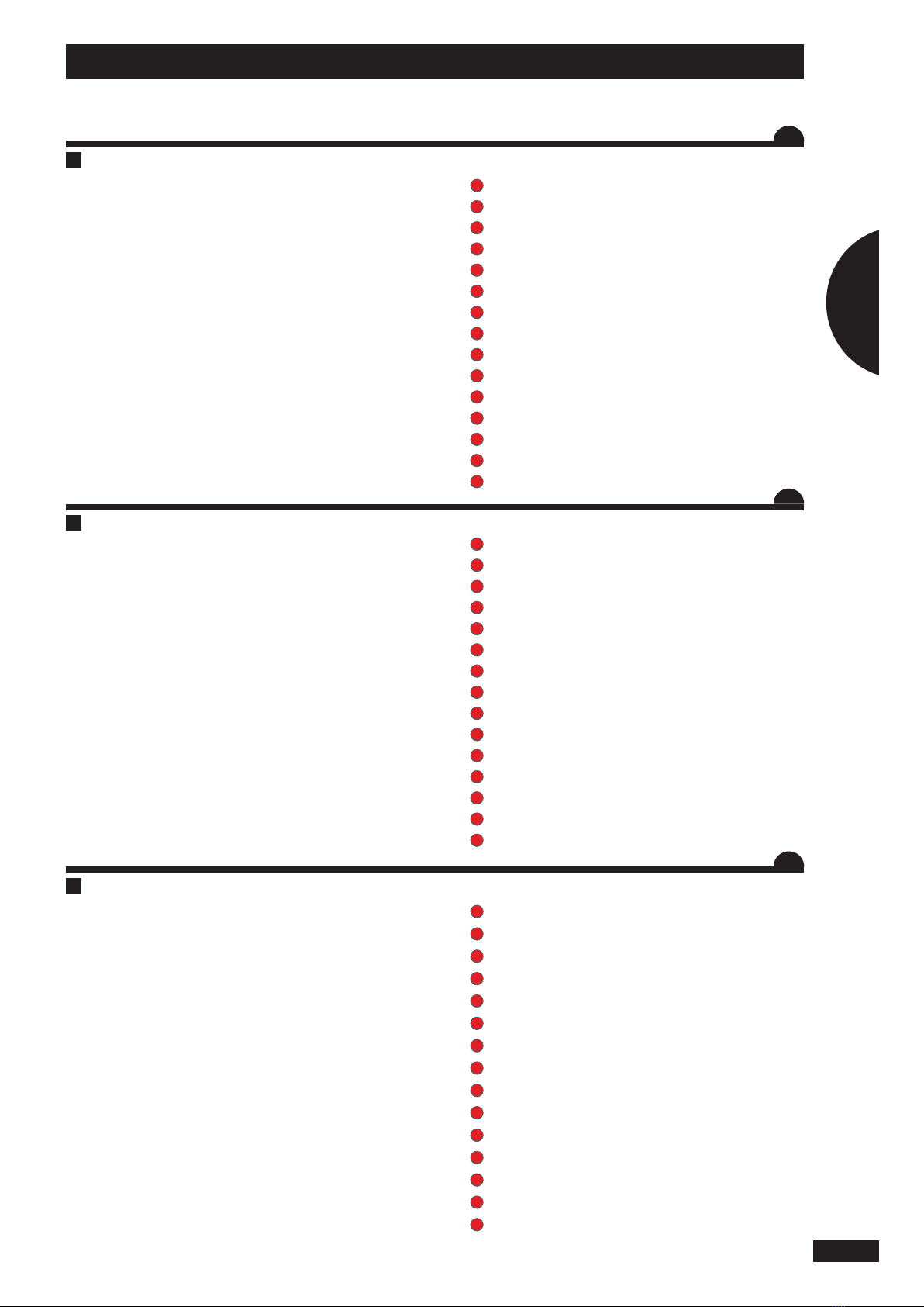
Français SOMMAIRE
Pages INFORMATIONS
Pages RÉGLAGE
Pages
6-7
8-9
10-11
12-19
• A
• B
• C
• D
Présentation du système VISION DUO
Connexion au tracteur
Boîtier de commande VISION DUO
Présentation des fonctions
PRÉSENTATION
46-47
48-49
50-51
50-51
52-53
54-55
56-57
58-59
60-61
62
63
63
• A
• B
• C
• D
• E
• F
• G
• H
• I
• J
• K
• L
Fonction pré-start
Fonction Précharge
Modulation
Vérins
Tramline
Information pour Jalonnage
Alarme
Réglages alarme
Réglages généraux
Pannes - Remèdes
Agriculture de précision
Consignes d’utilisation avec fertilisant
20-21
22-23
24-25
26-39
40-41
42-43
44-45
• A
• B
• C
• D
• E
• F
• G
Réglage de la largeur
Choix du produit (sauf trémie pro)
Modication de la dose en Kg/ha (sauf trémie pro)
Essai de débit
Modulation de dose
Réglage du jalonnage
Calibrage de la vitesse d’avancement
3
1
2
3
4

Pages INFORMATIONS
Pages SETTINGS
Pages
6-7
8-9
10-11
12-19
• A
• B
• C
• D
Presentation of the VISION DUO system
Tractor interface connections
VISION DUO control unit
Presentation of functions
PRESENTATION
46-47
48-49
50-51
50-51
52-53
54-55
56-57
58-59
60-61
62
63
63
• A
• B
• C
• D
• E
• F
• G
• H
• I
• J
• K
• L
Pre-start function
Pre-load function
Adjustment
Cylinders
Tramline
Tramlining information
Alarm
Alarm settings
General settings
Troubleshooting
Precision cropping
Instructions for use with fertilizer
20-21
22-23
24-25
26-39
40-41
42-43
44-45
• A
• B
• C
• D
• E
• F
• G
Setting the working width
Product selection (except PRO hopper)
Modifying the application rate in kg/ha (except PRO hopper)
Calibration test
Adjusting the application rate
Setting the tramlines
Calibrating the forward speed
4
English CONTENTS
Read the operator’s manual carefully before use. Understanding your electronic
unit will help you make better use of it. For English instructions, follow this symbol:
EN .
Seite INFORMATIONEN
Seite EINSTELLUNGEN
Seite
6-7
8-9
10-11
12-19
• A
• B
• C
• D
Beschreibung des Systems VISION DUO
Schlepperanschluss
Bedienkonsole VISION DUO
Beschreibung der Funktionen
BESCHREIBUNG
20-21
22-23
24-25
26-39
40-41
42-43
44-45
• A
• B
• C
• D
• E
• F
• G
Einstellung der Breite
Saatwahl (außer Saatguttank Pro)
Änderung der Saatmenge in kg/ha (außer Saatguttank Pro)
Aussaatmengentest
Änderung der Saatmenge
Einstellung der Fahrgassenschaltung
Kalibrierung der Fahrgeschwindigkeit
46-47
48-49
50-51
50-51
52-53
54-55
56-57
58-59
60-61
62
63
63
• A
• B
• C
• D
• E
• F
• G
• H
• I
• J
• K
• L
Funktion Anlaufhilfe
Funktion Vorfüllung
Änderung
Zylinder (Stellmotoren)
Tramline
Informationen für die Fahrgassenschaltung
Alarm
Alarmeinstellungen
Allgemeine Einstellungen
Störungen - Abhilfe
Präzisionslandwirtschaft
Gebrauchsanweisung für Düngemittel
5
Deutsch INHALTSVERZEICHNIS
Anleitung vor Benutzung sorgfältig durchlesen. Das Elektronikgerät richtig zu
verstehen, heißt, es besser (aus)nutzen zu können. Die deutsche Fassung ist
mit gekennzeichnet. DE .
1
2
3
6
A
Présentation / Presentation / Beschreibung
5
6
6
11
11
12
1
10
13
7
9
15
14
14
3
2
4
8
Beschreibung des VISION DUO-Systems
a) Einführung
• Der Bordcomputer VISION DUO ist ein Gerät zur
Einstellung und Kontrolle.
• Die von VISION DUO angegebenen Informationen über
Gewichte und Flächen dürfen nicht für Handelszwecke
verwendet werden.
b) Beschreibung
1
VISION DUO Bedienkonsole
2
VISION DUO-Schalkasten
3
Schaltkasten für den Motoranschluss
4
Stromanschluss Motor
5
Anschluss Steuergerät
6
Knopf für Verteilerfüllung und Abdrehprobe
7
Radar
8
Motoren
9
Hubwerksensor
10
Magnetventil Vorauaufmarkierer
11
Tank-Füllstandsensor
12
Anschluss VISION DUO Konsole
13
Cobo-Stecker (Stromversorgung Konsole)
14
Schließsensor Getriebe
15
Geschwindigkeitssensor Turbine
Presentation of the VISION DUO system
a) Introduction
• The VISION DUO unit is a control and monitoring tool.
• The weight and surface area information provided by
the VISION DUO should not be used for commercial
transactions.
b) Presentation
1
VISION DUO console
2
VISION DUO electronic unit
3
Motor interface electronic units
4
Motor power supply connector
5
Electronic unit connection
6
Distribution and calibration test start button
7
Radar
8
Motors
9
Lifting mechanism sensor
10
Pre-emergence tramlining solenoid valve (optional)
11
Hopper level sensor
12
VISION DUO console connector
13
Cobo plug (console power supply)
14
Gearbox closure sensor
15
Fan speed sensor
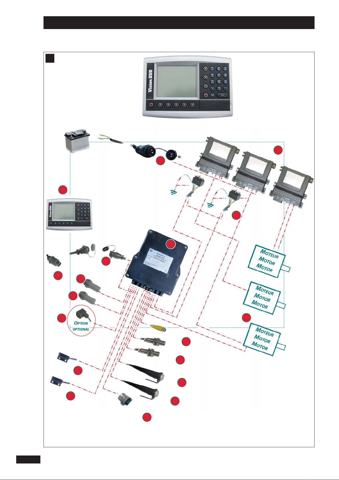
Présentation du système VISION DUO
a) Introduction
• La console VISION DUO est un instrument de réglage et
de contrôle.
• Les informations de poids et de surface données par la
console VISION DUO, ne peuvent pas être utilisées pour
des transactions commerciales.
b) Présentation
1
Console VISION DUO.
2
Boîtier électronique
3
Boîtiers électroniques interface moteur
4
Connecteur d’alimentation de puissance du moteur
5
Connexion boîtier électronique moteur
6
Boutons d’amorçage distribution et essai de débit
7
Radar
8
Moteurs
9
Capteurs de relevage
10
Électrovanne jalonneurs de prélevée (option)
11
Capteurs niveau de trémie
12
Connecteur console VISION DUO
13
Prise cobo (alimentation console)
14
Capteurs fermeture boîte de vitesse
15
Capteur vitesse turbine
7
FR
EN
DE
A
A
A
Présentation / Presentation / Beschreibung
1

8
Présentation / Presentation / Beschreibung
B
75 mm
142 mm
237 mm

Schlepperanschluss
Installierung des VISION DUO
• Die elektrischen Versorgungsleitungen des
Elektronikgerätes sind unbedingt direkt an die
12-V-Batterie des Schleppers anzuschließen.
• Wenn alle Stecker angeschlossen sind, kann der
Computer eingeschaltet werden.
• Die VISION DUO-Konsole hat einen Speicher für
programmierte Daten.
• Das Steuermodel VISIONDUO muss durch eine
5-A-Sicherung und die Stromversorgung des Motors/der
Motoren mit 40-A-Sicherungen geschützt werden.
• Die Konsole muss für den Fahrer gut sichtbar angebracht
werden.
Vor dem Unterbrechen der Verbindung, den
Computer vorschriftmäßig mit der Taste
ausschalten.
Es ist sehr wichtig, dass die Stromversorgung des
Elektronikgeräts VISION DUO und die Spannung
direkt aus der Batterie kommen und eine gemeinsa-
me Masse haben.
Tractor interface connections
Installing the VISION DUO
• The power supply cables must be connected directly to
the tractor’s 12 V battery.
• Once the plugs have been connected, the unit can be
switched on.
• The VISION DUO unit has a memory for the programmed
data.
• The VISION DUO console must be protected by 5A fuses
on its power supply, and 40A for the electrical power
supply to the motor(s).
• The console must be positioned so that it can be easily
seen by the driver.
Switch o the unit properly using the key before
unplugging it.
It is very important that the power supply for the
VISION DUO electronic unit and the power come
directly from the battery and that they share the
same earth.
Connexion au tracteur
Installation de la console VISION DUO
• Il est impératif de brancher les alimentations électriques
directement à la batterie 12 volts du tracteur.
• Lorsque les prises sont branchées, le boîtier peut être
allumé.
• La console VISION DUO possède une mémoire des
données programmées.
• La console VISION DUO doit être protégé par des fusibles
5A sur son alimentation, et 40A pour l’alimentation
électrique du ou des moteur(s).
• La console doit être positionnée de manière à ce qu’elle
soit bien visible par le conducteur.
Eteindre correctement le boîtier au moyen de la
touche avant de le débrancher.
Il est très important que l’alimentation du boîtier
électronique VISION DUO et l’alimentation de
puissance viennent directement de la batterie et
aient une masse commune.
9
FR
EN
DE
Présentation / Presentation / Beschreibung
1
B
B
B
10
Présentation / Presentation / Beschreibung
C
1
1
2
2
3
3
4
4
5
5
6
6
6
7
7
8
8
9
9
1
1
0
0
0
0
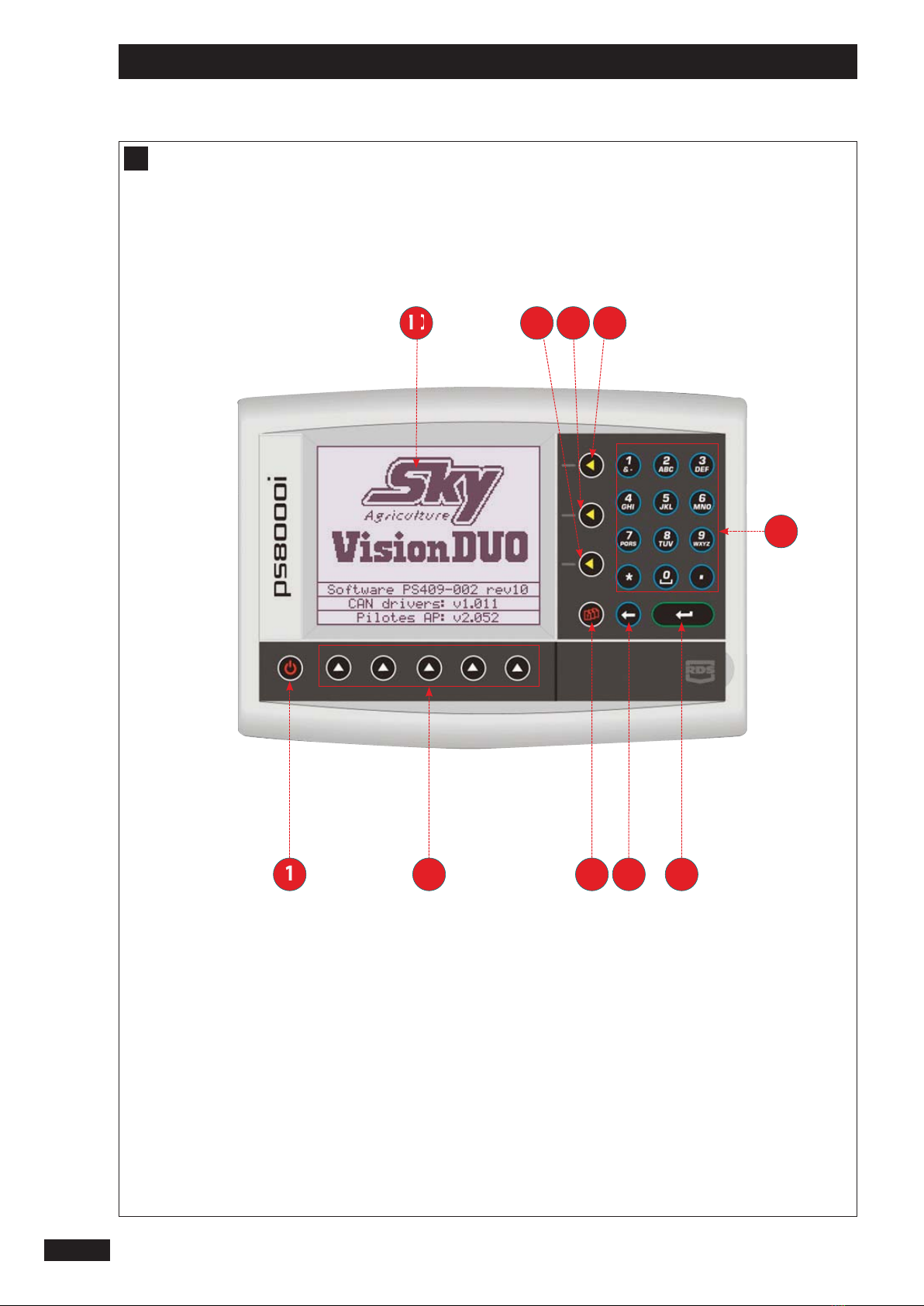
Bedienkonsole VISION DUO
1
Einschalten
2
Funktionen
3
Programmierungstaste (kurzer Druck) und Halb-
Sämaschine (langer Druck)
4
Retourtaste
5
Taste für «Bestätigung» oder «Eingabe» einer
Programmierung
6
Numerische und alphabetische Tastatur /
Dosiermengenänderung
7
Aktivierung / Stopp der Dosierer und Beginn der
«Anlaufhilfe» (langer Druck)
8
Aktivierung / Stopp des Sädosierers
9
Aktivierung / Stopp des Düngerdosierers
10
Multifunktionsanzeige
VISION DUO control unit
1
On button
2
Functions
3
Setup key (brief press) and half seed drill (prolonged
press)
4
Back key
5
Parameter «conrmation» or «input» key
6
Alphanumeric keypad / rate change
7
Start / stop the metering units and launch the «pre-
start» (prolonged press)
8
Start / stop the seed metering unit
9
Start / stop the fertilizer metering unit
10
Multifonction screen
Boîtier de commande VISION DUO
1
Mise sous tension
2
Fonctions
3
Touche paramétrage (appui bref)
et demi semoir (appui long)
4
Touche retour
5
touche de « conrmation » ou « entrée »
d’un paramétrage
6
Pavé numérique et alphabétique / changement de
dose
7
Activation / arrêt des doseurs et lancement
du « pre-start » (appui long)
8
Activation / arrêt du doseur semence
9
Activation / arrêt du doseur engrais
10
Écran multifonction
11
FR
EN
DE
Présentation / Presentation / Beschreibung
1
C
C
C
12
Présentation / Presentation / Beschreibung
D
1
1
2
2
3
3
Beschreibung der Funktionen
Das VISION DUO-Bedienkonsole wird mit Hilfe von drei
Menüs bedient.
Der Wechsel zwischen den Menüs erfolgt durch drücken der
Taste .
1
ᇍMenü Säen: Angewendet während der Arbeit
2
ᇍInformations-Menue : Turbinengschwindigkeit,
Flächenzähler
3
ᇍProgrammierungsmenü : Einstellung der Konsole
und der Sämaschine.
Hinweis:
Das Menü 3 untergliedert sich in seine Untermenüs.
Beispiel im Menü: .
Zum Aufruf des Beispiels 1 zur Betriebseinstellung ist die
entsprechende Taste auf der Tastatur zu drücken.
Presentation of functions
The VISION DUO console has three control menus.
Press the key to move from one menu to another.
1
ᇍSeeding menu: used when working.
2
ᇍInformation menu: Fan speed, surface meter
3
ᇍSetup menu: Setting the console and the seed
drill.
NB:
Menu 3 break down into sub-menus.
Example in the menu:
Using the keypad, press the key corresponding to the request
in example 1 for work settings.
Présentation des fonctions
Le contrôle de la console VISION DUO se fait à travers trois
menus.
Le passage d’un menu à l’autre se fait en appuyant sur la
touche .
1
ᇍMenu semis : Utilisé au travail.
2
ᇍMenu information : Vitesse de turbine, compteur
de surface
3
ᇍMenu paramétrage : Réglage de la console et du
semoir.
Remarque :
Le menu 3 se décompose en sous menus.
Exemple dans le menu : .
À l’aide du clavier, appuyer sur la touche correspondant à la
demande exemple 1 pour réglages travail.
13
FR
EN
DE
Présentation / Presentation / Beschreibung
1
D
D
D
a)
14
Présentation / Presentation / Beschreibung
D
{
1
1
2
2
3
3
4
4
4
5
5
6
6
6
7
7
8
8
8
9
9
1
1
0
0
0
0
1
1
6
6
6
6
1
1
5
5
5
5
1
1
5
5
5
5
1
1
2
2
2
2
1
1
1
1
1
1
1
1
7
7
7
7
1
1
3
3
3
3
1
1
4
4
4
4
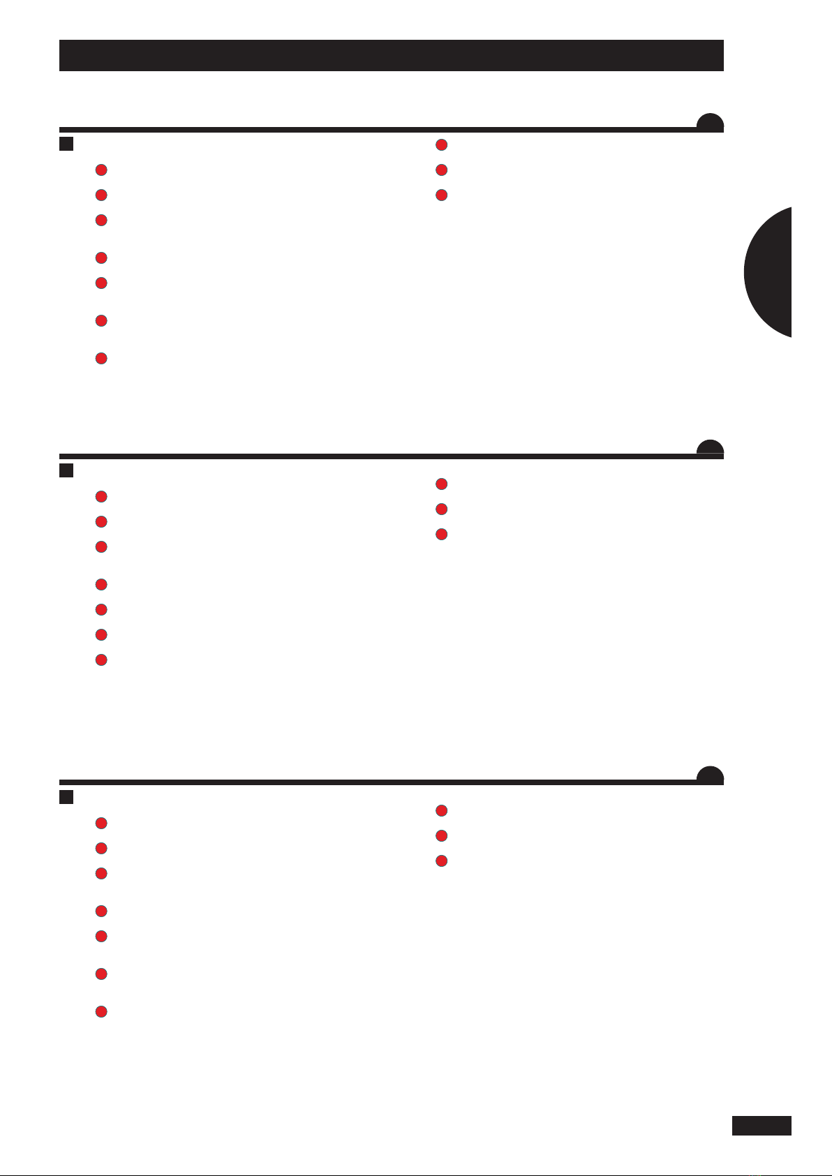
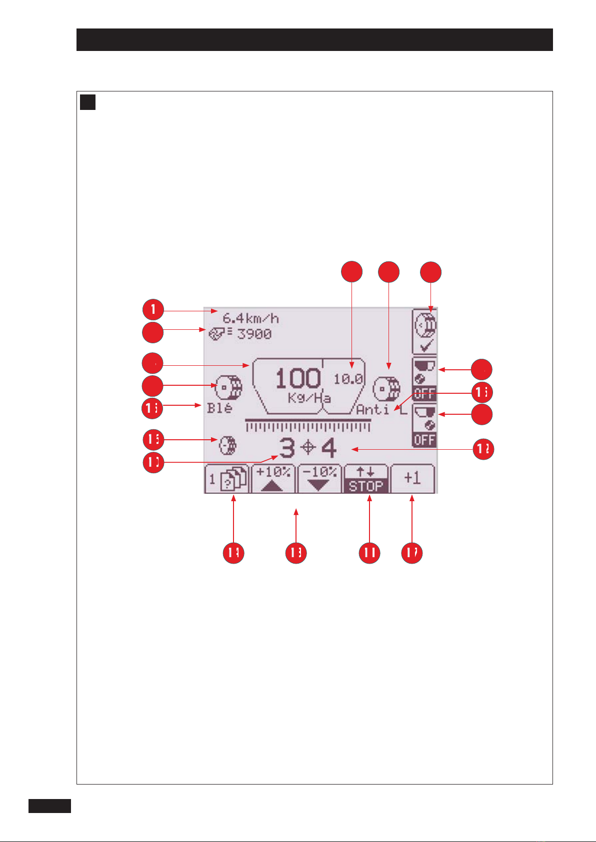
a) Menü Säen
1
Fahrgeschwindigkeit
2
Geschwindigkeit der Turbine
3
Symbol für die Rotation und Geschwindigkeit des
Saatgut-Dosierers.
4
Durch den Saatgutdosierer gelieferte Dosiermenge
(kg/ha) mit angehobener Maschine/Dosiermenge
(kg/ha) mit abgesenkter Maschine.
5
Durch den Saatgutdosierer gelieferte grogrammierte
Dosiermenge (kg/ha) mit angehobener Maschine/
Dosiermenge (kg/ha) mit abgesenkter Maschine.
6
Symbol für die Rotation und Geschwindigkeit des
Düngemittel-Dosierers.
7
Stopp der Dosierer/Funktion Anlaufhilfe mit langem
Druck
8
Aktivierung oder Stopp des Saatgutdosierers
9
Aktivierung oder Stopp des Düngemitteldosierers
10
Erhöhung um eine Fahrgasse, Fahrt im Gange
11
Abschaltung des Fahrgassenzählers
12
Anzahl der Fahrten zwischen jeder Fahrgasse
13
Stufenweise (10%) Änderung der
Ausbringungsmenge der Dosierer und Rücksprung
zur ursprünglichen Menge mit langen Druck
14
Weiter mit dem nächsten Menü
15
Gewählte Produktsorte
16
Symbol für die Rotation und Geschwindigkeit der
Dosiervorrichtung für den Saatguttank Pro (Option).
17
Erhöhung/Senkung um eine Fahrgasse
a) Drilling menu
1
Forward speed
2
Fan speed
3
Icon for rotation and seed metering unit speed
4
Application rate (kg/ha) programmed with the
machine lifted / application rate (kg/ha) delivered
with the machine lowered by the seed metering unit
5
Application rate (kg/ha) programmed with the
machine lifted / application rate (kg/ha) delivered
with the machine lowered by the fertilizer metering
unit
6
Icon for rotation and fertilizer metering unit speed
7
Stop the metering units / pre-start function using a
prolonged press
8
Start or stop the seed metering unit
9
Start or stop the fertilizer metering unit
10
Tramlining incrementation by one bout, bout in
progress
11
Stop the tramlining counter
12
Number of bouts between each tramline
13
Modify the application rate of the metering unit(s) in
increments of (10%) and return to the original rate
using a prolonged press
14
Continue to the next menu
15
Type of product selected
16
Icon for rotation and metering mechanism speed of
the PRO hopper (optional)
17
Tramlining incrementation by one bout
a) Menu semis
1
Vitesse d’avancement
2
Vitesse turbine
3
Visuel de rotation et de régime doseur semence
4
Dose (kg/ha) programmée machine levée /dose (kg/
ha) délivrée machine baissée par le doseur semence
5
Dose (kg/ha) programmée machine levée /dose (kg/
ha) délivrée machine baissée par le doseur ferti
6
Visuel de rotation et de régime du doseur ferti
7
Arrêt des doseurs / fonction pré-start avec un appui
long
8
Activation ou arrêt du doseur semence
9
Activation ou arrêt du doseur ferti
10
Passage de jalonnage en cours
11
Arrêt du comptage du jalonnage
12
Nombre de passage entre chaque jalonnage
13
Modulation de débit du ou des doseurs par palier de
(10%) et retour à la dose initiale par un appui long
14
Passage au menu suivant
15
Type de produit sélectionné
16
Visuel de rotation et de régime du doseur
de la trémie Pro (option)
17
Incrémentation d’un passage de jalonnage
15
FR
EN
DE
Présentation / Presentation / Beschreibung
1
D
D
D
b)
1
1
2
2
2
2
2
2
3
3
4
4
5
5
6
6
6
8
8
7
7
9
9
16
Présentation / Presentation / Beschreibung
D

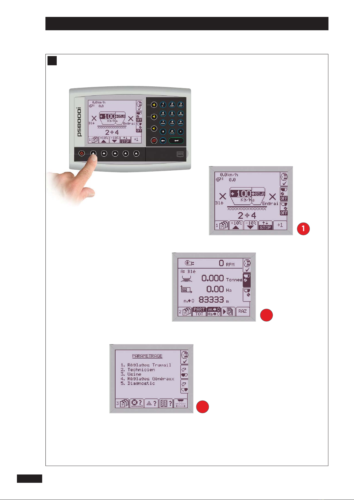
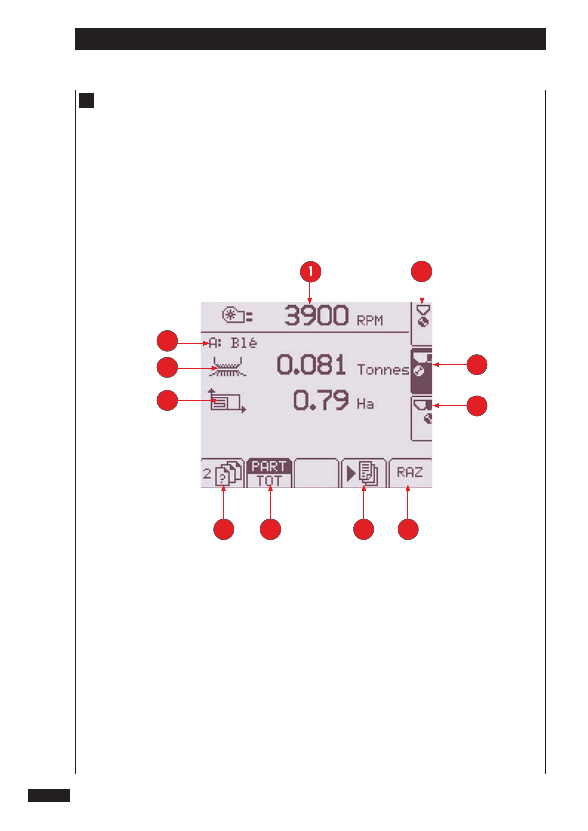
b) Menü Information
1
Drehgeschwindigkeit der Turbine
2
Gewählte Dosiervorrichtung (angezeigte
Informationen)
3
Nullstellung der gewählten Dosiervorrichtung
4
Programmierung für die Präzisionslandwirtschaft
5
Auswahl der Teil- oder Gesamtmenge
6
Weiter mit dem nächsten Menü
7
Theoretisches Gewicht des Produkts, das durch die
gewählte Dosiervorrichtung geführt wird
8
Theoretische Oberäche, auf die mit der gewählten
Dosiervorrichtung Saat aufgetragen wird
9
Gewählte Produktsorte
b) Information menu
1
Fan rotation speed
2
Selected metering mechanism (information displayed)
3
Reset selected metering mechanism
4
Setup for precision cropping
5
Select the partial or total surface
6
Continue to the next menu
7
Product theoretical weight passing into the selected
metering mechanism
8
Theoretical area drilled using the selected metering
mechanism
9
Selected product
b) Menu informations
1
Régime rotation turbine
2
Doseur sélectionné (informations achées)
3
Remise à zéro du doseur sélectionné
4
Paramétrage pour l’agriculture de précision
5
Sélection surface partielle ou totale
6
Passage au menu suivant
7
Poids théorique de produit passé dans le doseur
sélectionné
8
Surface théorique semée avec le doseur sélectionné
9
Produit sélectionné
17
FR
EN
DE
Présentation / Presentation / Beschreibung
1
D
D
D

18
Présentation / Presentation / Beschreibung
E
c)
{
1
1
2
2
3
3
4
4
5
5
6
6
6
7
7

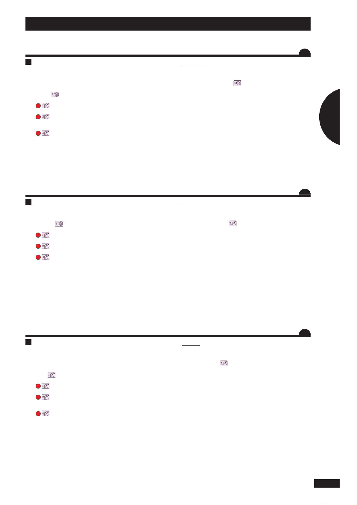
c) Einstellungsmenu
1
Untermenu
2
Dosierer ein/aus
3
Arbeitslänge und Halb-Sämaschinenfunktion
4
Einstellung der Fahrgasse
5
Kalibrierung der Dosierer
6
Kalibirierung der Fahrtgeschwindigkeit/und
Geschwindigkeitssimulator
7
Weiter mit dem nächsten Menü
c) Menu réglage
1
Sous menus
2
Marche / arrêt du doseur
3
Largeur de travail et fonction demi-semoir
4
Réglage du jalonnage
5
Calibrage des doseurs
6
Calibrage de la vitesse d’avancement / et simulateur
de vitesse
7
Passage au menu suivant
c) Settings Menu
1
Submenus
2
Metering unit on / o
3
Working width and half seed drill function
4
Tramline setting
5
Calibration of metering units
6
Forward speed calibration / and speed simulator
7
Continue to the next menu
19
FR
EN
DE
Présentation / Presentation / Beschreibung
1
D
D
D

1
1
2
2
20
A
Réglage / Settings / Einstellungen
Table of contents
Popular Control Panel manuals by other brands


Bosch
Bosch B9512G-E installation manual

C-TEC
C-TEC CAST XFP Commissioning & Programming Quick Start Guide

Bentel Security
Bentel Security KYO 320 user manual

Geberit
Geberit AquaClean 147.038.SI.1 user manual

ABB
ABB CP435 Installation and operation manual

Digital Monitoring Products
Digital Monitoring Products XTLplus Series Installation and programming guide

Honeywell
Honeywell NOTIFIER INSPIRE E10 installation instructions

Proteco
Proteco myGate Q81A instruction manual

Radionics
Radionics D269 user guide

Leviton
Leviton EZ-MAX H Series installation manual

Johnson Controls
Johnson Controls IFC-3030 Operation manual

Nittan
Nittan CPC-4A-24 Operating instructions manual