ABB CP435 User manual

CP435
Installation and Operation Manual
ABB, 1SBC159108M0201 2008-09 English
Cover_MAEN959.fm Page 1 Friday, August 29, 2008 2:23 PM

Foreword
ABB, 1SBC159108M0201
CP435 Installation and Operation Manual
Foreword
CP435 is a Human Machine Interface (HMIs) with a 7" TFT Liquid Crystal
Display, and is water- and dust-resistant according to IP65/NEMA 4X (indoor
use only).
CP435 is CE-marked and meets your need to be highly transient-resistant
while in operation.
Also, its compact design makes connections with other machinery more flexi-
ble, thus achieving the optimal performance of your machines.
CP400Soft is used to design applications of CP435; it is reliable, user-friendly
and compatible with many models.
Copyright © ABB
All rights reserved.
Release: Sept. 2008
Document number: ABB, 1SBC159108M0201
Please read the entire installation manual prior to installing and using this equipment.
Only qualified personnel may install, operate or repair this equipment. ABB is not responsible for modi-
fied, altered or renovated equipment.
Because the equipment has a wide range of applications, users must acquire the appropriate knowledge to
use the equipment properly in their specific applications.
Only parts and accessories manufactured according to specifications set by ABB may be used.
ABB SHALL NOT BE LIABLE TO ANYONE FOR ANY DIRECT, INDIRECT, SPECIAL, INCI-
DENTAL OR CONSEQUENTIAL DAMAGES RESULTING FROM THE INSTALLATION, USE
OR REPAIR OF THIS EQUIPMENT, WHETHER ARISING IN TORT, CONTRACT, OR OTH-
ERWISE.
BUYER'S SOLE REMEDY SHALL BE THE REPAIR, REPLACEMENT, OR REFUND OF PUR-
CHASE PRICE, AND THE CHOICE OF THE APPLICABLE REMEDY SHALL BE AT THE SOLE
DISCRETION OF ABB.

Contents
ABB, 1SBC159108M0201
Contents
1 Saftey Precautions................................................................................... 5
2 Installation.............................................................................................. 7
2.1 Package Contents.........................................................................7
3 Product Specifications ........................................................................... 8
3.1 Description of Parts ...................................................................10
3.2 External and Cut-out Dimensions .............................................11
3.3 Mounting Procedure ..................................................................11
3.4 Grounding .................................................................................12
3.5 Power Supply and Wiring ..........................................................13
4 Dip Switches......................................................................................... 14
5 Communication Ports........................................................................... 15
6 Operation ............................................................................................. 17
6.1 Self Test .....................................................................................17
6.2 System Menu ............................................................................. 18
6.3 Key Pad......................................................................................19
6.4 Bench and Function Tests ..........................................................20
6.5 Setting Communication Parameters...........................................20
6.6 Touch Screen Calibration...........................................................21
6.7 Downloading an Application .....................................................22
6.8 Uploading an Application ..........................................................23
6.9 Uploading/Downloading a Recipe .............................................24
6.10 Copying an Application .............................................................25
6.11 Passwords...................................................................................26

Contents
ABB, 1SBC159108M0201

Saftey Precautions
ABB, 1SBC159108M0201 5
1 Saftey Precautions
Both the installer and the owner and/or operator of the operator terminal must
read and understand this installation manual.
General
– Only qualified personnel may install or operate the operator terminal.
– The operator terminal must be installed according to the installation instruc-
tions.
– The operator terminal is designed for stationary installation on a plane surface,
where the following conditions are fulfilled:
• no high explosive risks
• no strong magnetic fields
• no direct sunlight
• no large, sudden temperature changes
• for use in Pollution Degree 2 Environment
• for use on the flat surface of Types 1 and 4X (indoor use only) enclosures
– Never allow fluids, metal filings or wiring debris to enter any openings in the
operator terminal. This may cause fire or electrical shock.
– The operator terminal fulfills the requirements of article 4 of EMC directive
2004/108/EC.
– Storing the operator terminal where the temperature is lower/higher than
recommended in this manual can cause the LCD display liquid to congeal/
become isotopic.
– The LCD display liquid contains a powerful irritant. In case of skin contact,
wash immediately with plenty of water. In case of eye contact, hold the eye
open, flush with plenty of water and get medical attention.
– The supplier is not responsible for modified, altered or reconstructed equip-
ment.
– Use only parts and accessories manufactured according to specifications of the
supplier.
– Peripheral equipment must be appropriate for the application and location.
– The figures in this manual serves an illustrative purpose. Because of the many
variables associated with any particular installation, the supplier cannot as-
sume responsibility for actual use based on the figures.
– The supplier neither guarantees that the operator terminal is suitable for your
particular application, nor assumes responsibility for your product design, in-
stallation or operation.

Saftey Precautions
6ABB, 1SBC159108M0201
Power source
– The operator terminal is equipped with a 24 V DC input. Supply power other
than 24 V DC ± 15% will severely damage the operator terminal. Thus, check
the power supply supporting the DC power regularly.
Grounding
– Without grounding, the operator terminal may be severely affected by excess
noise. Make sure that the grounding is done properly from the power connec-
tor at the rear side of the operator terminal. When power is connected, make
sure that the wire is grounded.
– Use a cable of at least 2 mm2(AWG 14) to ground the operator terminal.
Ground resistance must be less than 100 Ω (class3). Note that the ground
cable must not be connected to the same ground point as the power circuit.
Installation
– Communication cables must be separated from power cables for operational
circuits. Only use shielded cables to avoid unpredictable problems.
During Use
– Emergency stop and other safety functions may not be controlled from the
operator terminal.
– Do not use too much force or sharp objects when touching the keys, display
etc.
Service and Maintenance
– Only qualified personnel should carry out repairs.
– The agreed warranty applies.
– Before carrying out any cleaning or maintenance operations, disconnect the
equipment from the electrical supply.
– Clean the display and surrounding front cover with a soft cloth and mild
detergent.
– Replacing the battery incorrectly may result in explosion. Only use batteries
recommended by the supplier.
Dismantling and Scrapping
– The operator terminal or parts thereof shall be recycled according to local
regulations.
– The following components contain substances that might be hazardous to
health and the environment: lithium battery, electrolytic capacitor and
display.
Installation
ABB, 1SBC159108M0201 7
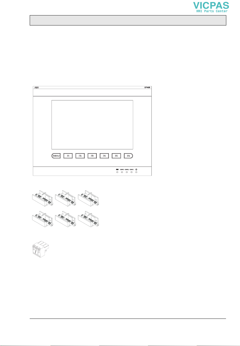
2Installation
2.1 Package Contents
The following parts are found in the box:
– Operator terminal CP435
– 6 installation fasteners
– Power connector (connected to the 24 V DC power input)
– Installation and operation manual (1SBC159108M0201)

Product Specifications
8ABB, 1SBC159108M0201
3 Product Specifications
Parameter CP435 T CP435 T-ETH
Front panel, W x H x D 231.0 x 176.0 x 7.5 mm
Mounting depth 45.8 mm
Cut-out dimensions 220.8 x 165.8 mm
Front panel seal IP 65/NEMA 4X (indoor use only)
Keypad specifications 1 “Menu”-key and 6 user-defined function keys (F1-F6).
Pressure: 280 ± 50 gf operating force.
Lifetime: over 1,000,000 activations.
Weight 1.2 kg
COM 1 9-pin female connector: RS232/RS485
COM 2 25-pin female connector: RS232/RS422/RS485
COM 3 9-pin female connector: RS422/RS485
Ethernet - Yes
USB Host 2 ports
USB Device 1 port
Flash ROM 8 MB
RAM 16 MB
CPU 32-bit RISC
Battery backed memory 512 KB
Data/Recipe 512 KB
CF card port Yes
Real time clock Yes (with rechargeable lithium battery)
Display Color TFT LCD, 64K colors, 800 x 480 pixels.
CCFT backlight lifetime: approximately 50,000 h at 25 °C
Active area of display,
W x H 153.7 x 92.4 mm.
100 x 60 characters of 8 x 8 size can be displayed.
Display adjustment Via touch screen
Touch screen Analog
Power supply 24 V DC ± 15%. Less than 24 W.
Ambient temperature 0 ° to +50 °C
Storage temperature -10 °to +60 °C

Product Specifications
ABB, 1SBC159108M0201 9
Ambient humidity 20 - 90% RH non-condensed
Vibration endurance 0.5 mm displacement, 10-55 Hz, 2 hours per X-, Y- and
Z-axis directions
Shock endurance 10 G, 11 ms 3 times in each direction of X-, Y- and Z-axes
CE EN61000-6-4, EN61000-6-2
Cooling Natural cooling
Parameter CP435 T CP435 T-ETH
Product Specifications
10 ABB, 1SBC159108M0201
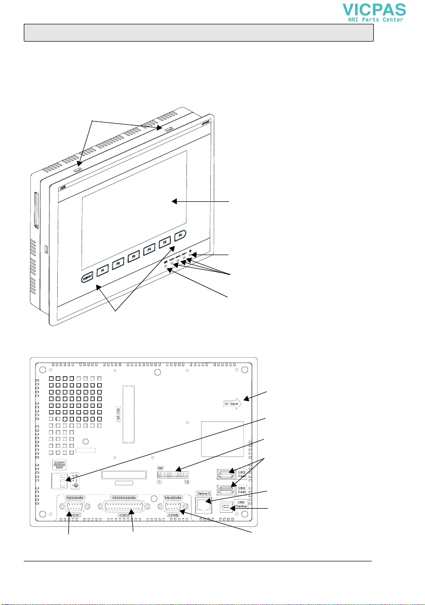
3.1 Description of Parts
Front
Back
Fixture mounting holes
Power lamp
Communication lamps
Function keys
Display
Network lamp
DIP switches (1-12)
COM2: RS232/RS422/RS485
DC power input
COM1: RS232/RS485
Network connection
USB port for
CF card connection
USB port for transmission
COM3: RS422/RS485
printer/memory stick
This manual suits for next models
2
Table of contents
Other ABB Control Panel manuals

ABB
ABB CP 600 Series User manual

ABB
ABB Eurofire EN54 Quick start guide

ABB
ABB ControlMaster CM10 Use and care manual

ABB
ABB ACSM1 Series User manual

ABB
ABB ACS850 series Troubleshooting guide

ABB
ABB CP660-x User manual

ABB
ABB CP430 User manual

ABB
ABB Controlpanel User manual

ABB
ABB CP420B User manual

ABB
ABB ACS580 Series User manual

ABB
ABB CP420 User manual

ABB
ABB ACS-AP Series User manual

ABB
ABB AC-AP Series User manual

ABB
ABB Welcome IP IPTouch 7" Series User manual

ABB
ABB CP600-eCo User manual

ABB
ABB ACS-AP-x User manual

ABB
ABB CP405 User manual

ABB
ABB CP450 T User manual

ABB
ABB ACS850 series User manual

ABB
ABB ACQ580 Troubleshooting guide


