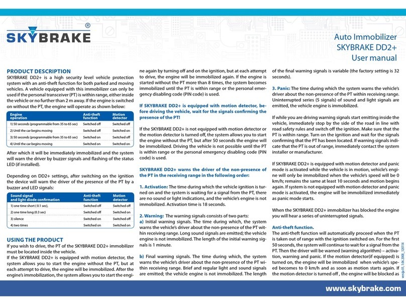
Skybrake DD2+ User manual

versija 01, 1.06.2008_120114
DD2+ installation manual
1. OPERATING PRINCIPAL OF THE SYSTEM
A vehicle equipped with the Skybrake DD2+ anti-theft device can only be used if the
Personal Transceiver (PT) is within range – either inside the vehicle or not further than
two meters from it. If the engine is switched on without the PT, the engine operates in
accordance with the process indicated in Table No.1.
Engine Anti-theft Motion
operation function detector
1) 50 seconds (programmable from 35 to 65 sec) Switched o Switched o
2) Until the car begins moving Switched o Switched on
3) 50 seconds (programmable from 35 to 65 sec) Switched on Switched o
4) Until the car begins moving Switched on Switched on
Afterwards the engine is immediately immobilized, and this is conrmed by sound signals
and ashing of the status LED (if this is installed).
Depends of Skybrake DD2+ model and conguration, after switching on the ignition the
driver is informed of the presence of the PT with sound signals and ashing of the status
LED. These signals can be used to determine which of the Skybrake DD2+ functions are
switched on:
Sound signal Anti-theft Motion
and light diode conrmation function detector
1) one time short ( 0.1 sec), Switched o Switched o
2) one time long (0.3 sec) Switched o Switched on
3) silence Switched on Switched o
4) two times Switched on Switched on
To be able to drive the vehicle, the PT must be inside the vehicle.
The Skybrake DD2+ system lets you start the engine without the presence of the PT (only
in cases where the motion detector is switched on). In this case the vehicle’s engine will be
immobilized as soon as movement begins. If the ignition is turned o and then turned on, it
is possible to start the engine again. The engine will be immobilized as soon as movement
begins. If the engine is switched on/o without the PT more then 8 times, the engine be-
comes immobilized. The engine will remain immobilized until the PT is within range or the
personal emergency disabling code (PIN) is used.
Skybrake DD2+ warns the driver of the non-presence of the PT in the receiving range in the
following order:
1. Activation: The time during which the vehicle ignition is turned on and the system is
waiting for a signal from the PT, there are no sound or light indications, and the vehicle’s
engine is not immobilized. Activation time is 18 seconds.
2. Warning: The warning signals consists of two parts:
a) Initial warning signals. The time during which the system warns the vehicle’s driver
about the non-presence of the PT within receiving range. Long sound signals are emitted;
the vehicle engine is not immobilized. The length of the initial period warning signals is 1
minute.
b) Final warning signals. The time during which the system warns the vehicle’s driver about
the non-presence of the PT within receiving range. Brief and regular light and sound signals
are emitted; the vehicle engine is not immobilized. The length of the nal warning signals is
variable (the factory setting is 32 seconds).
3. Panic: The time during which the system warns the vehicle’s driver about the
non-presence of the PT within receiving range. Uninterrupted series (5 signals) of sound
and light signals are emitted, the vehicle engine is immobilized.
If panic mode is activated while the vehicle is in motion, the vehicle’s engine will only be
immobilized when the vehicle’s speed will be 0 km/h, remains the same at least 10 seconds
and movement begins again.
If while you are driving warning signals start emitting inside the vehicle, immediately stop
by the side of the road in line with road safety rules and switch o the ignition. Make sure
that the PT is within range. Turn on the ignition and wait for the signals conrming that the
PT has been located. If warning signals indicate that the PT is out of range, immediately
contact the system installer or manufacturer.
If the vehicle’s engine has been blocked by the Skybrake DD2+ immobilizer, each time the
ignition is switched on the driver will be warned about the blocked engine with series of
light and sound signals (5 signals).
2. WIRE MARKING, CONNECTION TO THE VEHICLE’S ELECTRICAL SYSTEM
It is recommended that the Skybrake DD2+ control unit should be placed inside the vehicle
or in the engine compartment in a place that is dicult to access, if possible away from
metal and heat-impacted surfaces, and also avoiding dampness and seepage of water into
the control unit.
The system’s control unit must be xed to the selected surface with double-sided adhesive
tape or plastic clips, with the wires facing downward.
Make sure that the wires of the system’s control unit are not near moving and heat-impacted
surfaces of the vehicle.
„-” – chassis.
To be rmly screwed on to the vehicle’s body (31). The “chassis” wire must be attached rst.
„+” – ignition.
Must be attached to the wire using a 3A fuse, in which, with the ignition switched on and
the engine in “START” mode, +12V (15) voltage appears and does not disappear. This is the
system’s power wire.
“7” – outlet to the buzzer’s black wire.
The main output to the buzzer’s black wire and LED, for additional visual control of the
system’s operation. The transistor’s open collector output with maximum permitted load
capacity of 500mA. It is recommended that the buzzer is placed inside the vehicle under a
panel in a place where its sound is not mued.
It is recommended that the LED is placed on the vehicle’s front panel in a visible area.
Attention: The status LED is not included in the manufacture’s standard equipment.
Attention: Do not mix up the polarity of the buzzer and the LED wires as the sound and
visual indication will disappear in this case.
“1” – engine cut-o circuit.
Internal relay 20A. The relay contacts are linked (NC) when the system is unblocked and with
the ignition turned on. The engine cut-o circuit is intended for halting power supply to the
engine’s electrical circuits.

versija 01, 1.06.2008_120114
Make sure that the ends of the wires have not been mixed up when installing the system as
this could seriously damage the vehicle’s electrical system.
Recommendation: Try to use untraditional engine immobilization circuits, after seeking the
advice of a competent auto dealer whether a specic short circuit will not harm the vehicle’s
electrical system.
In case of non-observance of the instructions, the technician installing the system will
forfeit the manufacturer’s warranty for this product.
The manufacturer reserves the right to change the construction of the immobilizer if this
does not contravene national laws and complies with Russian Federation and EU technical
standards. Any changes must be noted in the usage and installation instructions.
3. THE PERSONAL TRANSCEIVER PT
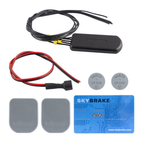
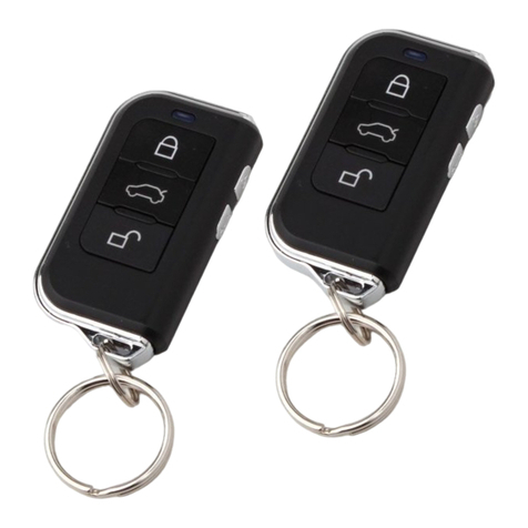
The Skybrake DD2+ set includes two PTs. The CR2430 batteries included in the set are not
placed in the PT battery contacts.
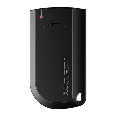
The personal transceiver consists of (see image Nr.2):
lThe upper and lower transceiver casing;
lElement plate;
l3 V CR2430 battery.
Note the battery’s polarity and the markings on element plate!
In order not to damage the element plate, the PT must be placed in the casing without force
and only in one specied position.
After setting up the system, it is necessary to check the operation of the PT:
lPlace the battery (1) in the contact holder (2) in line with the indicated polarity;
lA few seconds after inserting the battery, observe the light diode located on the
element plate.The light diode should ash 4 times, indicating that the battery is functioning
normally. If the light diode does not ash, replace the battery with the new one;
lTurn on the ignition and wait for the light diode to ash again. The ashing of the light
diode indicates that normal radio contact has been established between the system and
the PT;
lPlace the PT in the casing (3).
Attention: After turning on the ignition, the system will warn the driver of the need to
change the battery with three double sound signals emitting inside the vehicle.
4. MOTION DETECTOR
The motion detector is a device built into the system which keeps track of changes in the
vehicle’s position in relation to the ground and existing or commenced acceleration, i.e. it
keeps track of whether the vehicle is moving (driving) or stationary.
Taking into account the fact that vehicles of diering masses and dimensions create
diering vibrations and acceleration while driving, the sensitivity of the motion detector
can be changed (see Changing settings/programming modes)
lIt is only possible to ascertain the minimum or maximum level by performing a check
(commencing movement), or using special software.* After setting up the system it is
necessary to test the operation of the motion detector.
To check whether the sensitivity level of the motion detector is not too low:
lGet in the vehicle;
lRemove the battery from the PT;
lTurn on the engine and wait 5 seconds;
lBegin driving slowly and evenly; if the motion detector is set correctly, the vehicle’s
engine will immediately cut out and be immobilized;
lIf movement starts and the vehicle’s engine continues running, you must increase the
motion detector’s sensitivity (see “Changing settings/programming modes”).
After inspecting the motion detector, insert the battery in the PT’s contact holder in line
with polarity and place it in the casing.
5. ANTITHEFT FUNCTION
The anti-theft function is activated while the driving the PT is taken out of the system’s
receiving range. For the rst 50 seconds the Skybrake DD2+ control unit continues to wait
for a signal from the PT (activation). After that, warning signals will sound to warn the driver
(warning algorithm) If the motion detector (if equipped) is turned on, the engine will be
blocked when vehicle’s speed wiil be 0 km/h (and remains the same for at least 10 seconds)
and as soon as motion starts again. If the motion detector is turned o, the engine will be
blocked as soon as panic starts. Driving will not be possible until the PT is within range of
the system or the personal emergency disabling code (PIN) is used.
Skybrake DD2+ anti-theft function is prohibited in the Russian Federation and the EU.
Attention: Regarding the switching on and switching o of the anti-theft function, see
the section “Changing settings/programming modes”.
6. ADDITIONAL ENGINE CUTOFF MODULES
It is possible to install a maximum of 3 additional radio controlled engine cut-o modules
together with the Skybrake DD2+ central module.
The additional cut-o module’s technical parameters, wire marking, installation
requirements and connection diagram are the same as for the central module, except for:
lThere is no sticker with the serial number on the plastic casing;
lThere is no wire Nr. 7 – the output to the buzzer’s black wire.
Cut-o modules suitable for the respective serial number must be produced for each
Skybrake DD2+ central module, so that these modules cannot be attached to other central
control modules. The central control module automatically recognizes additional cut-o
modules immediately after they are installed.
If the Skybrake DD2+ central unit is installed together with an additional cut-o module,
removal of the additional module will cause the system to block, because the central unit
will not receive information from the cut-o module.
Attention: When installing the Skybrake DD2+ central module or cut-o modules, do
not disrupt/cut-o the modules’ power supply chains.
7. EMERGENCY SYSTEM DISABLING
To use the vehicle without a PT you will require a special PIN code consisting of four digits
(for example, 3241). The system manufacturer will give you a card with the PIN code.
lTurn on the ignition;
lWait until the engine is immobilized and a series of warning signals emits inside the
vehicle;
lTurn o the ignition and prepare to enter the PIN code;
lTurn on the ignition, when the warning signals series emit start counting them, when the
number of sound signal series aligns with the rst digit of the PIN code (e.g. 3), turn o the
ignition (the rst digit of the PIN code has been entered);
lTurn on the ignition and continue counting the sound signal series until their number
aligns with the second digit of the PIN code – (e.g. 2), then turn o the ignition;
lTurn on the ignition and repeat the above steps with the third (4) and fourth (1) digits of
the PIN code;
lWhen turning on the ignition after entering the last PIN code digit, you will hear a sound
signal – the Skybrake DD2+ system is disabled;
lThe next time you turn o and turn on the ignition, the vehicle engine will be blocked and
you will have to repeat the PIN code entering procedure;
lIf you make a mistake while entering the PIN code, with the ignition turned on wait for a
series of 12 sound signals, turn o/turn on the ignition and enter the PIN code again;
lUse of the PT automatically renews the normal operating mode of Skybrake DD2+.
l4 sound signals – the moving into car’s salon has been detected
8. CHANGING SETTINGS/PROGRAMMING MODES
ATTENTION: The certied installer has special equipment and software to perform
computer-assisted programming.
The system intaller can:
1. Turn on/turn o the motion detector
2. Change the sensitivity of motion detector
3. Turn on/turn o the anti-theft function
4. Change the length of warning signals
5. Add new PT to the system
6. Enable/disable existing PT
7. Save/read out information from PT ( vehicle registration number, VIN number)
Description of technical parameters for Skybrake DD2+
Nr. Parameter name Parameter value
1. Operating frequency 2400 – 2480 GHz
2. Transceiver’s emitted power ≤ 1 mW
3. Modulation form GFSK
4. Number of channels 125
5. Data exchange speed 1Mbit/s
6. Operating voltage 6-16 V
7. Power consumption (unblocked condition ) 0.015A
8. Power consumption ( immobilized condition ) 0.115A
9. Maximum power consumption in immobilization circuit 20A
10. Maximum load at buzzer/diode exit 0.5A
11. System fuse 3A
12. Operating temperature of immobilizer No -40˚C to +85˚C
13. Operating temperature of Personal Transceiver (PT) No -40˚C to +55˚C
THE SKYBRAKE DD2+ SET
Skybrake DD2+ module 1
Personal Transceiver 2
CR-2430 battery 2
Buzzer 1
Emergency disabling code (PIN code) 1
1
2
3
Other Skybrake Car Alarm manuals

