Skye DataHog2+ User manual

DataHog2+
Skye Instruments Ltd
21, Ddole Enterprise Park
Llandrindod Wells
Powys, LD1 6D , UK
Tel: +44 (0) 1597 824811
Email: [email protected]
www.skyeinstruments.com
Iss. 1.0

DataHog2+
Skye Instruments Ltd
Skye Instruments is based in the UK and we are very proud to be celebrating being in
business since 1983. ur products are designed and built in the UK. We have a very wide
product base and our sensors & systems are used for plant & crop research; micro-climate,
global climate change studies; environmental monitoring and controlled environment
installations.
Products include light sensors & systems, weather monitoring sensors, automatic weather
stations, plant research systems, soil and water research systems.
Feel free to contact us via our e-mail, or any of the methods below:
Click on the icons to browse to the sites, or search for the usernames below.
Have a Smartphone? Scan this QR code to access our website for more information about
your product:
Please be aware that the information in this manual was correct at time of issue, and should be 100%
relevant to the accompanying product. We take great pride in our ever-evolving range of products, which
means that sometimes the product may change slightly due to re-design.
If you have any queries, please do not hesitate to contact our technical team by any of the methods
above.
PLEASE NOTE – SKYE, DATAHOG, SPECTROSENSE, MINIMET, HYDROSENSE, APOLLO,
ARE TRADEMARKS O SKYE INSTRUMENTS LTD
2
Skye.Instruments
Skye Instruments Ltd. @SkyeInstruments SkyeInstrumentsVideo
Skye Instruments Ltd.

DataHog2+
CONTENTS
1.0 Introduction 5
2.0 verview & Quick Start 7
2.1 Inside the enclosure _________________________________________ 7
2.2 SDHC Card verview ________________________________________ 8
2.2.1 Removing & Inserting the SDHC card ________________________ 8
2.3 Power Supply ______________________________________________9
2.3.1 Solar Power Supply _____________________________________9
2.4 Pole Mount/Bracket _____________________________________ 10
2.5 Activity LEDs _______________________________________________ 10
2.5.1 Troubleshooting of the Activity LEDs _________________________ 10
3.0 DataHog2
3.1 Memory 13
3.2 Channels 14
3.2.1 Voltage input channels 14
3.2.2 Current input channels 15
3.2.3 Internal temperature channel 16
3.2.4 Digital input channels 16
3.2.5 Internal relative humidity channel 17
3.2.6 Software channels 17
3.2.7 Relay output channels 17
3.3 Calibration 17
3.4 Firmware 18
4.0 peration 19
4.1 Initial set up 19
4.1.1 Firmware overview 19
4.1.2 Logging mode overview 19
4.1.3 Main menu mode overview 19
4.2 Main menu mode options 20
4.2.1 ption 0 - Display readings from all active channels 21
4.2.2 ption 1 - Display current setup 21
4.2.3 ption 2 - Display software version 22
4.2.4 ption 3 - ffload 24 hour data summary 22
4.2.5 ption 4 - ffload data 23
4.2.6 ption 5 - Reset memory 23
4.2.7 ption 6 - Set clock 23
4.2.8 ption 7 - Set Datafile Identifier, Plus Memory verwrite & Timed
Logging Modes 24
4.2.9 ption 8 - Set channel sample and log intervals 25
4.2.10 ption 9 - Set AX+B calibration factors 27
4.2.11 ption A - Set channel configuration 28
4.2.11a Voltage Inputs 0 – 23 29
3

DataHog2+
4.2.11b Current Inputs 25 – 40 30
4.2.11c Internal Temperature Reference – 45 31
4.2.11d Digital Count Channels 48 – 53 32
4.2.11e Internal Humidity Channel – 54 33
4.2.12 ption B - Set internal RH% sensor calibration 34
4.2.13 ption C - Set alarm relay(s) 34
4.2.14 ption D - Set channels for non zero / threshold log modes 35
4.2.15 ption E - Enter ‘Log on Demand’ mode 36
4.3 Care for your DataHog2 36
5.0 Connections 37
5.1 RS232 Connector 37
5.2 Light Sensors 38
5.3 Temperature Sensors (Thermistors) 39
5.4 Single-Ended Voltage Sensors 39
5.5 Differential Voltage Sensors 39
5.6 Digital Sensors 39
5.7 Potentiometer Sensors 40
5.8 Special Socket – RH & Air Temperature Sensors 40
5.9 Relay utputs _____________________________________________ 40
6.0 SkyeLynx Comms Software 41
7.0 Importing Data into Excel 42
8.0 Power Supply ptions 43
Fig. 1 ACC/1A RS232 Datalead 44
Fig. 2 Sub Miniature Plugs 46
Fig. 3 DataHog Sockets Pin Identification 47
Appendix 1 Summary of codes used in configuration 48
Appendix 2 Setting up Full Scale Values for Digital Channels 49
Appendix 3 Setting up Full Scale Values for Differential Voltage Channels 50
Appendix 4 Setting up Potentiometer Inputs 52
Appendix 5 Solar Panel Regulator Board __________________________________ 56
Appendix 6 Attaching the Solar Panel to a Mast _____________________________ 57
Appendix 7 Files on the SDHC Card _______________________________________ 59
4

DataHog2+
1.0 Introduction
The SDL 5000 series of DataHog2+ dataloggers comprise an electronically advanced
datalogging system for a variety of environmental sensors.
The logger is centred on a high performance generation 8 bit microprocessor (p). This
has the ability to perform all the mathematical and logging tasks and then close down to
conserve power.
Depending on the datalogger model there are one or more analogue to digital
converters which render the signals from the sensor into a digital form that can be
handled by the microprocessor. These have a resolution of 15 bits which means that
analogue signals such as light, which vary over several decades, can be properly
handled and give adequate resolution of measurement over the required range.
Many versions of the DataHog2+ are available, with different combinations of voltage,
current and digital inputs. This manual covers all models, and so will include sections that
are not applicable to individual units. Please check those parts of the manual that apply
to your model and type of your unit and ignore inapplicable sections.
In normal logging mode the p will be ‘woken up’ by the clock at regular 10 second
intervals. The p will keep track of real time by counting the number of times it is woken
up and storing the time in the RAM while the p is asleep! nce woken up, the
microprocessor will perform the tasks required of it (depending on the logging mode
previously selected) and then when these are complete will return to ‘sleep’ to conserve
power.
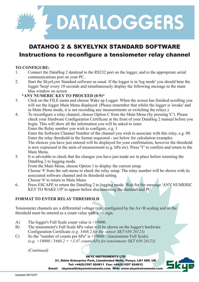
The microprocessor can communicate with the user’s host computer via its built in RS232
interface, and can be controlled by instructions sent via this. It also gives some feedback
to the user via the audio transducer (beeper) built in.
Immediately before the p closes down to ‘sleep’ mode, if there is a plug connected to
the 8 pin RS 232 socket, then it will ‘listen’ for a command from the user for a period of
about 1 second. During this time, preceded by an audible ‘beep’, any numeric character
sent to the DataHog2+ will cause it to enter terminal (or Main Menu) mode.
The datalogger is usually contained in a polycarbonate housing, which is sealed to IP
65. The sockets, when mated to a matching plug or blanking unit are also weatherproof
to IP65.
5

DataHog2+
Do not panic! Although some sections of this manual may at first sight appear involved and
complex, you quite probably may never need to read them. Your DataHog2+ datalogger is
supplied set up with all scaling factors configured for the sensors it is supplied with. After
connecting the power supply, the DataHog should start working. If in doubt, check the section
of the manual you think appropriate, and if trouble persists phone or email Skye or your
sales Agent. We will do our best to help. A quick phone call or email may save you hours of
pondering. Good Luck!
!!! Don't forget
A DataHog2+ needs power to operate. It cannot work with a flat battery or without being
connected to a 12v supply.
If your DataHog2+ seems unresponsive, it quite possibly just has a flat battery - so first check
the state of the 12 volt battery – see Appendix 2
DataHog2+ logger is a DataHog2 with additional electronics for extra storage of the data
on a removable multi-media card. DataHog2+ will still store data in its internal memory at the
same time, but will also store data on the Multi-Media (SDHC) card. There is no need to
offload the data from the internal memory storage, as a copy will have been made on the
SDHCHC card. If for any reason the SDHCHC card has become corrupted, then please refer
to Section 3.2.5 for instructions on how to offload the data from the internal storage module.
A datalead and SkyeLynx Comms, PC software will also have been supplied. These will only
be required if you wish to change any of the DataHog configurations, such as sample and
log times. Please refer to Section 3 for instructions on how to accomplish this task.
The logger has been set up at Skye with as much information as possible for immediate
operation. Where supplied with Skye sensors the appropriate scaling factors, zero offsets,
gains etc have already been entered, as shown on the Hardware Configuration Certificate
which is supplied with your system. The default logging interval is 30 minutes, but this can be
changed by connecting the logger to an Android mobile phone or Tablet with the FTDI UART
app installed, or to a laptop/PC running Windows.
6

DataHog2+
2.0 OVERVIEW AND QUICK START
The DataHog2+ comprises the DataHog2 datalogger with the addition of the DHLC3
electronics to provide a datalogger which stores data on a removable Multimedia (SDHC)
card.
2.1 Inside the Enclosure
1 Underneath this metal plate are the DataHog2 electronics
2 Solar Panel regulator
3 8 pin socket. For normal operation the plug – 3a – will be plugged into this
socket.
For changing any configurations & set-ups, this plug is removed and the plug
from the datalead is inserted.
4 DHLC3 electronics board
5 Row of Activity/Function LEDs
6 SDHC card holder
7 Push button for activating the blue LED for SDHC card removable
8 Blue LED
9 Power supply connection block. Connection from the 12V battery which is then
distributed to the unit
10 PSU reset. nly used on rare occasions. The main reason for pressing this will be
when the DataHog2+ is used with a PC for accessing the setup menu. After
removing the plug from the DHLC3 board (3a) and then plugging in the 8 pin
connector from the datalead (which will be connected to the PC), the PSU reset
7
1
2
3
5
4
6
7
8
910
3a

DataHog2+
will need to be pressed. A faint click will be heard. If no click is heard then there
is a problem with the power supply.
2.2 SDHC Card - overview
The SDHC card needs to be formatted (FAT 16 or 32) on a PC. The maximum size of SDHC
card that can be used is 32GB and the type is SDHC Class 4.
To insert the SDHC card hold the top of the card with the notched end at the bottom and
facing towards the inside of the enclosure
Slide the SDHC card into the holder and push down until you hear a click. The card is now in
place.
To remove the card, gently press down on the card and then let go. This will release it from
the locking mechanism
2.2.1 Removing & Inserting the SDHC Card in Use
The SDHC card is located inside the enclosure and is quite visible when the lid has been
removed.
PLEASE D N T ATTEMPT T REM VE THE SDHC CARD WITH UT F LL WING THESE
INSTRUCTI NS
1) Press the button next to the SDHC card/SDHC card holder.
2) A blue LED will light up. This will be alight for 1 minute and 20 seconds, which
should be ample time to remove the SDHC card and insert a new one. nly
remove the SDHC card when the LED is alight. If you attempt to remove the
SDHC card while the blue LED is off, then you can damage or corrupt the SDHC
card.
8
Notched end

DataHog2+
The DHLC3 buffers datastrings whilst this LED is alight so no data is lost. Data in the buffer will
be sent to the SDHC card 5 seconds after the LED goes out.
At the configured logging interval the DataHog sends a 'datastring'. This datastring contains
the date and time of the stored data, channel number and data:
This 'datastring' is stored on the SDHCHC card in a 'day file'. A new day file is automatically
created at midnight. Day files are a space delimited text file and easily read by any
spreadsheet software. Please refer to Appendix 7 for details of the SDHC card structure.
2.3 Power Supply
The unit requires an external 12 volt power supply for operation. The white cable from the
enclosure should be connected to the battery terminals
2.3.1 Solar Power
9
To negative terminal of the battery
To positive terminal of the battery
Connectors from the solar panel click
into these connectors on the enclosure.
A tool is supplied to aid the removal of
these connectors should it be
necessary

DataHog2+
Please refer to Appendix 6 for instructions on how to mount the solar panel on a pole.
2.4 Pole Mount/Bracket for the DataHog2+ SKM 225A
If a pole mount has been ordered at the same time as the DataHog2+, then the enclosure
will be pre-mounted on the bracket. Connection holes, accessible by removing the lid of the
enclosure, line up with holes in the mounting plate. A pair of 'V' bolts plus nuts etc are
supplied so that the unit can be fixed to a pole.
2.5 Activity LED Lights
There are 8 coloured LED lights which light up and flash in different sequences depending on
the intended function or activity.
When the power supply is first connected all the LEDs will continually flash in turn, until the
DataHog has undergone its setup routine. When this has happened the DataHog will settle
into its normal operating routine as follows:
LED 1 - DataHog 'wake-up' string is detected
LED 2 - DataHog 'datastring' detected
LED 3 - Complete 'datastring' successfully received
LED 4 - 'Datastring' stored on the SDHC card successfully
LED 5 - Indicates a search is being made for the 'datastring' but none was found
LED 6, 7 & 8 – SDHC card storage attempt failed.
10
'V' bolts for fixing bracket to a pole
through these holes

DataHog2+
2.5.1 Trouble-shooting LED Sequences
LEDs 6, 7 & 8 continuously flash
Indicates a full SDHC card.
In this scenario, LEDs 1,2,3,4 & 5 will not light even though the DataHog is still running. No
storage will be taking place on the SDHC card as it is full, but the DataHog will continue to
store to its internal memory as long as that isn't also full.
No buffering will be taking place and all datastrings will be lost until a new card is inserted.
If, by mistake, a full SDHC card is inserted instead of a blank one, then the above LED
sequence will occur.
LEDS 6,7 & 8 continuously flash and LEDS 1,2,3,4 & 5 flash according to the datastrings
generated by the DataHog
This indicates either no SDHC card is present or the SDHC card is faulty.
No buffering occurs and all datastrings will be lost until a new card is inserted.
LEDs 6,7,& 8 giving a single flash and LEDs 1,2,3,4 & 5 flash according to datastrings
generated by the DataHog.
This sequence occurs if the SDHC card is removed whilst the unit is running. Please note that in
this situation the SDHC card could have been corrupted. See section 2.2 for details on how
to remove the SDHC card safely.
No buffering occurs and all datastrings are lost until an SDHC card is inserted.
11

DataHog2+
The rest of this manual is a very detailed description of the
DataHog2 how it operates how to configure the many settings
plus wiring information of the many sensors which can be used.
Some parts will not be applicable to the DataHog2+. DataHog2+
does not have any internal batteries so please disregard any
reference to internal batteries in the following pages.
Changing any of the configuration settings can be achieved by
using the SkyeLynxComms software and datalead supplied with
your system. Unplug the connector shown as no. 3 in the photo
above and plug in the 8 pin plug on the end of the datalead
Please note. The DataHog2+ must be powered before connecting a
datalead and pc.
12

DataHog2+
3.0 DataHog2
3.1 Internal (on-board) Memory
The DataHog2+ loggers all have solid state, battery backed Random Access Memory.(RAM).
This stores all the logged data and also calibration factors etc. The on-board lithium cell
should provide back-up power for approximately ten years. Because of this memory back-
up, data is retained when the main batteries are flat or disconnected for replacement, but no
logging is possible from this back-up power. It should be noted though that it is good
practice to offload data from the unit before the main batteries are exhausted if at all
possible.
Depending on the model of 5000 series, the RAM may hold up to 11,001 records of data and
time (1 record includes date, time and a measurement of each channel) or nearly 30,000
measurements each with a time and date stamp, in 121,020 bytes. The amount of spare
memory can be checked in ptions 1 then 5 from the Main Menu. The following table gives a
useful guide to the number of bytes used per channel and records available at different
logging intervals:
TABLE F INTERNAL ( N-B ARD) MEM RY SIZE AND USAGE
The internal memory of your DataHog2+ is split between a few locations required for housekeeping
and the bulk of the storage capacity which is devoted to data storage. The data is stored in a format
that is constant. Basically the data from each channel that has been gathered at one time is stored
together with the date and time at which the data was obtained. Thus the channel data (from 1 to 8
channels) plus the time is a set number of records. Clearly the fewer the number of channels in use, the
greater the number of records available for storage. The table below shows the maximum number of
records for different numbers of channels in use and illustrates the time before memory is full at different
logging intervals.
Channels Bytes per
record
Records
available
Logging
1 min.
Interval
10 min 30 min 2 hrs
1 11 11,001 7.6 days 10.9 wks 32.7 wks 2.5 yrs
2 15 8,068 5.6 days 8.0 wks 24.0 wks 1.8 yrs
3 19 6,369 4.4 days 6.3 wks 18.9 wks 1.5 yrs
4 23 5,261 3.6 days 5.2 wks 15.6 wks 1.2 yrs
5 27 4,482 3.1 days 4.4 wks 13.3 wks 1.0 yrs
6 31 3,903 2.7 days 3.8 wks 11.6 wks 46 wks
7 35 3,457 2.4 days 3.4 wks 10.2 wks 41wks
8 39 3,103 2.1 days 3.0 wks 9.2 wks 37 wks
9 43 2,814 1.95 days 2.8 wks 8.3 wks 33 wks
10 47 2,574 0.78 days 2.5 wks 7.6 wks 30 wks
11 51 2,372 1.64 days 2.3 wks 7.0 wks 28 wks
12 55 2,200 1.52 days 2.2 wks 6.5 wks 26 wks
16 71 1,904 1.18 days 1.4 wks 5.0 wks 20 wks
13

DataHog2+
25 103 1,175 19.6 hours 8.1 days 3.5 wks 14 wks
3.2 Channels
There are two ‘types’ of channels with DataHog2+, hardware channels and software
channels. The former is the electronic hardware that is fitted to your DataHog2+. The
hardware that you have will be shown in the front of this manual in the “Hardware
Configuration Certificate”. There are potentially 54 hardware channels, though only a total of
16 can ever be in any one DataHog2+. Channels can be used for a variety of inputs as is
shown on your certificate, eg. voltage, current, digital, etc. The electronic components will be
different in each case according to which input type that channel has been dedicated.
The connections for external sensors to the hardware channels will be marked on the
Hardware Configuration Certificate located in the Calibration Certificates booklet provided
with each logger. The connections and calibration for those sensors that require it, will be
covered in subsequent sections of the manual.
3.2.1 Voltage Input Channels
In reality each is a differential amplifier (that is an amplifier which measures the voltage
difference between both its inputs) but which has been has been arranged so that each of
its inputs may be used as a separate channel if required. Usually only one or two of these
channels will be fitted on any logger, though the full list is shown below.
Hardware Channel Number Function and Description
0 Single ended Voltage Input, gain = 1, 10,100, or 1000
1 Single ended Voltage Input, gain = 1, 10,100, or 1000
2 Differential Voltage Input, gain = 1, 10,100, or 1000
(note that channel 2 uses the connections of channels 0 and 1)
3 Single ended Voltage Input, gain = 1, 10,100, or 1000
4 Single ended Voltage Input, gain = 1, 10,100, or 1000
5 Differential Voltage Input, gain = 1, 10,100, or 1000
(note that channel 5 uses the connections of channels 3 and 4)
6 Single ended Voltage Input, gain = 1, 10,100, or 1000
7 Single ended Voltage Input, gain = 1, 10,100, or 1000
8 Differential Voltage Input, gain = 1, 10,100, or 1000
(note that channel 8 uses the connections of channels 6 and 7)
9 Single ended Voltage Input, gain = 1, 10,100, or 1000
10 Single ended Voltage Input, gain = 1, 10,100, or 1000
11 Differential Voltage Input, gain = 1, 10,100, or 1000
(note that channel 11 uses the connections of channels 9 and 10)
12 Single ended Voltage Input, gain = 1, 10,100, or 1000
13 Single ended Voltage Input, gain = 1, 10,100, or 1000
14 Differential Voltage Input, gain = 1, 10,100, or 1000
(note that channel 14 uses the connections of channels 12 and 13)
14

DataHog2+
15 Single ended Voltage Input, gain = 1, 10,100, or 1000
16 Single ended Voltage Input, gain = 1, 10,100, or 1000
17 Differential Voltage Input, gain = 1, 10,100, or 1000
(note that channel 17 uses the connections of channels 15 and 16)
18 Single ended Voltage Input, gain = 1, 10,100, or 1000
19 Single ended Voltage Input, gain = 1, 10,100, or 1000
20 Differential Voltage Input, gain = 1, 10,100, or 1000
(note that channel 20 uses the connections of channels 18 and 19)
21 Single ended Voltage Input, gain = 1, 10,100, or 1000
22 Single ended Voltage Input, gain = 1, 10,100, or 1000
23 Differential Voltage Input, gain = 1, 10,100, or 1000
(note that channel 23 uses the connections of channels 21 and 22)
3.2.2 Current Input Channels
Note that each of these is a separate input to a current amplifier which can have any of
eight different feedback resistors. The effect of these resistors is to set the scaling of the
channel. The full scale of the DataHog2 is reached when 2.000 volts is applied to the
Analogue to Digital converter by this current amplifier. The ratio of current in to voltage out
(to the A/D converter) is set by this feedback resistor. It’s precise value is given in the
configuration certificate for each DataHog2. The ratio of current in to voltage out is given by
the following:-
Current in for F/S voltage out (2.000) = 2.0000 volts / feedback resistor value (Megohms)
The individual resistors fitted are very stable in value, but each has a slightly different value.
See the configuration certificate for the actual values fitted, but nominal values for each
‘current gain’ setting (resistor value Megohms / F/S input currents) are as follows:-
0) 0.005M / 400uA 1) 0.01M / 200 A 2) 0.05M/ 40uA 3) 0.1M / 20uA
4) 0.5M / 4uA 5) 1.0M/ 2uA 6) 5.0M/ 0.4uA 7) 10.0M / 0.2uA
Again, only one or two of these are usually fitted, but the full list is as follows:-
Hardware Channels Number Function and Description
25 Current Input - ‘current gain’ settable as above, 0) to 7)
26 Current Input - ‘current gain’ settable as above, 0) to 7)
27 Current Input - ‘current gain’ settable as above, 0) to 7)
28 Current Input - ‘current gain’ settable as above, 0) to 7)
29 Current Input - ‘current gain’ settable as above, 0) to 7)
30 Current Input - ‘current gain’ settable as above, 0) to 7)
31 Current Input - ‘current gain’ settable as above, 0) to 7)
32 Current Input - ‘current gain’ settable as above, 0) to 7)
33 Current Input - ‘current gain’ settable as above, 0) to 7)
34 Current Input - ‘current gain’ settable as above, 0) to 7)
15

DataHog2+
35 Current Input - ‘current gain’ settable as above, 0) to 7)
36 Current Input - ‘current gain’ settable as above, 0) to 7)
37 Current Input - ‘current gain’ settable as above, 0) to 7)
38 Current Input - ‘current gain’ settable as above, 0) to 7)
39 Current Input - ‘current gain’ settable as above, 0) to 7)
40 Current Input - ‘current gain’ settable as above, 0) to 7)
N.B. a) Current channel inputs are intended for use with Skye Instruments light sensors and so
show a positive reading for a negative current input with respect to ground. If these channels
are used with a sensor giving a positive current output with respect to ground, then the
DataHog will show a negative current.
b) Current sourcing sensors that can apply greater than 2 volts to these inputs when they are
not active, may cause errors on other channels.
3.2.3 Internal Temperature Channel
This is fitted only as an integral air temperature sensor, or as the 12th thermistor channel
where 12 thermistor channels are required. If it is fitted, it may be addressed as channel 45,
and will give an output as per a standard thermistor channel
Hardware Channel Number Function and Description
45 Thermistor only channel. Scale as a thermistor (10K)
3.2.4 Digital Input Channels
Low speed inputs. These accept switch closure inputs or 5 volt pulse inputs. The maximum
counting rate is 300 pulses per second.
N.B. Digital channels may only be ascribed to one software channel.
Hardware Channel Number Function and Description
48 Counting channel. Max count = 65535 before rollover
49 Counting channel. Max count = 65535 before rollover
50 Counting channel. Max count = 65535 before rollover
51 Counting channel. Max count = 65535 before rollover
52 Counting channel. Max count = 65535 before rollover
53 Counting channel. Max count = 65535 before rollover
Note that with a sampling time of 1 hour, the maximum count rate is approximately 18 per
second if a rollover is to be avoided with a sensor such as windspeed, sample times should
be kept below 10 mins to avoid rollover.
3.2.5 Internal Relative Humidity Channel – earlier models of DataHog2 only
16

DataHog2+
This hardware is simply addressed as hardware channel 54. As for all other hardware
channels it may be ascribed to any or all of the 25 software channels.
Hardware Channel Number Function and Description
54 ‘Built in’ Relative Humidity Channel.
3.2.6 Software Channels
The second type of channel or rather use of the word ‘channel’ is the software channel. This
simply refers to the way that the software has been configured to look at the hardware. For
example, if a hardware channel is fitted to the DataHog2+ it may be treated and read from
the software as software channel 0 - 24 depending on how the software is configured. Many
DataHog2+ s use a preset configuration option, but all can be individually configured to use
available hardware channels as the user desires.
e.g. more than one software channel can read from a single hardware channel, this is
especially useful if each software channel is set with a different gain for readings over a wide
range.
N TE - each digital hardware channel should not have more than one software channel
assigned to them, as once they have been ‘read’ by the first software channel the counter is
returned to zero.
3.2.7 Relay utput Channels
These channels can be fitted at the time of ordering your DataHog2+. Up to 4 relay outputs
are available, which can be assigned to any software channel. More than one can be
assigned to a single software channel if a “window” threshold is required.
The relay contacts are gold plated for low level relay switching and hence are for light duty,
low inrush switching only. They are not suitable for direct mains connection, inductive loads or
loads over 0.5amps. Slave relays should be used if these ratings are to be exceeded. The
built-in relays have a very low contact resistance, and are suitable for dry switching circuits.
3.3Calibration
Calibration of the sensor depends on the model in question, some units, for example with
curve matched thermistor temperature sensors, will not need specific calibration, this being set
at the time of manufacture. thers with external light sensors, or RH probes can be easily
calibrated in software.
17

DataHog2+
Sections later in this manual give specific details for calibration of the various channel and
sensor options. Please note that this manual contains the instructions for all models and
options. Please ignore those that do not apply to your specific unit.
3.8 Firmware
As previously mentioned, the units are designed for low power operation, and this is at least
in part achieved by switching off as much of the circuitry for as long as possible. This means,
amongst other parts of the unit, the RS232 interface (which has a high current requirement),
and hence the communication channel with you, the user, is switched off for most of the time.
However the software has been arranged so that in most modes there is a period of
‘listening’ on the RS232 to see if you wish to ‘talk’ to the unit. This period is generally
immediately after the microprocessor has done the tasks required of it during each ‘wake up’
period (every ten seconds). In most cases a message is sent from the DataHog2+ via RS232
requesting a response. An audible beep generally precedes the second or so that the unit
spends listening.
The DataHog2+ will only spend this extra time with the RS232 interface switched on if it
‘thinks’ that there is someone likely to want to ‘talk’ to it. The microprocessor monitors the
‘plug detect’ line - pin 6 socket 1 - and if this is shorted to ground, as by a suitably wired
datalead connected to the RS232 input, then it will ‘listen’.
************************************************************************************
N.B. If for any reason a connection lead is used without the ‘plug detect’ pin connected to
ground, then, although in most modes some data will be sent FR M the 5000 series
DataHog2+, it will not respond to characters sent from the host computer T the DataHog2+.
************************************************************************************
During the listening period if any numeric character is sent to the unit at the correct baud rate
it will immediately stop what it is doing and enter ‘terminal’ or Main Menu mode. The unit will
then send a ‘menu’ to the host with various options These options are listed in subsequent
sections
The baud rate for current software versions is 9600 Baud. ther details are 8 data bits, stop
bits, no parity, and xon/xoff flow control.
18

DataHog2+
4.0 OPERATION
4.1 Initial Set Up
The logger has been set up at Skye with as much information as possible for immediate
operation. Where supplied with Skye sensors the appropriate scaling factors, zero offsets,
gains etc have already been entered, as shown on the Hardware Configuration Certificate at
the front of this manual. In many cases the user simply needs to set the sampling and storing
periods desired and start logging.
4.1.1 Firmware verview
Firmware means the programme that is running within the DataHog2+ itself, not on the PC.
This programme is stored in a ‘R M’ (Non-volatile Read nly Memory) chip.
The DataHog2+, as previously mentioned, is designed to save power when
possible, and thus will ‘sleep’ for long periods compared to the time it spends
working. Essentially, it has two modes of operation which are referred to as
Logging Mode and Main Menu mode.
4.1.2 Logging Mode verview
To conserve power the DataHog2+ shuts down circuits not currently in use whenever possible.
In Logging Mode the operation is cyclic. It is ‘woken’ after approx. 8 seconds by the internal
clock, it will collect and store data from channels according to the various settings made by
the user in Main Menu mode.
‘Listening’ is a strange term, but the DataHog2+ is simply monitoring its RS232 input for any
numeric character sent by a computer connected to it. As soon as the DataHog2+ receives
such a character (assuming it arrives within the one second listening period) the DataHog2+
will leave logging mode and enter the Main Menu mode. If the character arrives too late,
then the DataHog2+ will simply go back to ‘sleep’ and listen again about 10 seconds later.
4.1.3 Main Menu Mode verview
Main Menu mode is entered when a character is received as described above. This can be
achieved by using the SkyeLynx Comms software and choose Wake Up Logger.
The DataHog2+ transmits the Main Menu showing the various functions and setup choices it
has to offer. These are described further in section 3.2. In essence, each option will either
19

DataHog2+
display status, offload data, configure and calibrate the logger, etc, returning the user to the
Main Menu when the individual task is completed.
Main Menu mode can only normally be left and Logging Mode re-entered by pressing
Escape on the PC keyboard.
N TE – always press Escape to leave Main Menu mode and return to Log Mode. Else the
logger will not record any data and batteries will drain quickly.
4.2 Main Menu Mode ptions
This is accessible from the SkyeLynxComms software
Main Menu mode is entered from Logging Mode by choosing File and Wake Up Logger, or
by pressing a numeric key on the keyboard during the ‘listening’ period of the DataHog2+, 1
second after the ANY NUMERIC KEY T WAKE UP message is seen. A menu of options is
displayed as below and may be selected from by typing the menu option number or letter:
SKYE INSTRUMENTS LTD. MINIMET SERIES
SEND CHARACTER SH WN T SELECT ITEM
<ESC> RETURNS T L GGING
-MAIN MENU -
0) DISPLAY READINGS FR M ALL ACTIVE CHANNELS
1) DISPLAY CURRENT SETUP
2) DISPLAY S FTWARE VERSI N
3) FFL AD 24H UR DATA SUSDHCHCARY
4) FFL AD DATA
5) RESET MEM RY
6) SET CL CK
7) SET DATAFILE I/D, PLUS MEM VERWRITE & TIMED L GGING M DES
8) SET CHANNEL SAMPLE & L G INTERVALS
9) SET AX+B CALIBRATI N FACT RS
A) SET CHANNEL C NFIGUR’NS
B) SET INT’NL RH% SENS R CALIB’N
C) SET ALARM RELAY(S)
D) SET CHANNELS F R N NZER / THRESH LD L G M DES
E) ENTER ‘L G N DEMAND’ M DE
In general upper case characters are expected. <Escape> will cancel almost all operations
before changes take effect!
Not all of these options apply to all models of the DataHog2+ family and consequently,
those functions that do not apply to a particular unit will be found to be inoperative.
20
This manual suits for next models
1
Table of contents
Other Skye Data Logger manuals
Popular Data Logger manuals by other brands
Capetti Elettronica
Capetti Elettronica WSD12PS-4AI user manual
Dickson
Dickson SP100 Getting started
National Instruments
National Instruments CF-6004 USER GUIDE AND SPECIFICATIONS

National Instruments
National Instruments NI 781 R Series user manual
Aim
Aim MyChron 3 660 Technical documentation

Huawei
Huawei FusionModule 1000B Maintenance Guide
