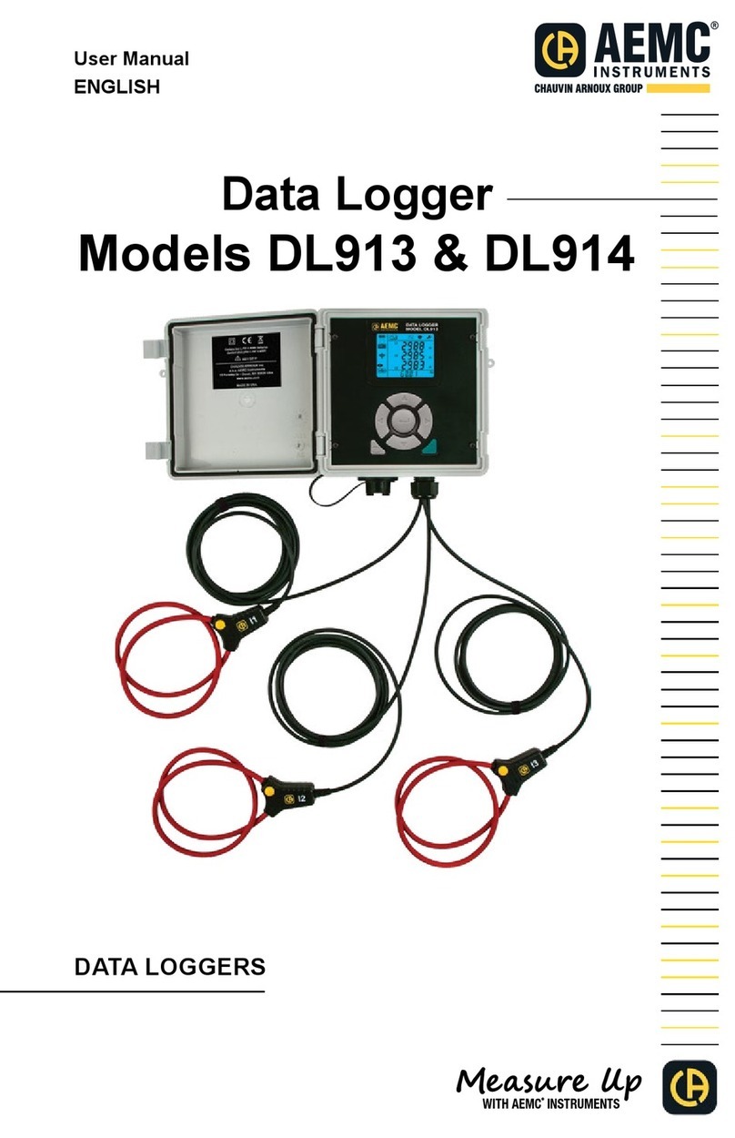
AEMC instruments DL913 User manual

www. .com information@itm.com1.800.561.8187

Copyright © Chauvin Arnoux®, Inc. d.b.a. AEMC® Instruments. All rights reserved.
No part of this documentation may be reproduced in any form or by any means (including electronic
storage and retrieval or translation into any other language) without prior agreement and written consent
from Chauvin Arnoux®, Inc., as governed by United States and International copyright laws.
www. .com information@itm.com1.800.561.8187

Statement of Compliance
Chauvin Arnoux®, Inc. d.b.a. AEMC®Instruments
using standards and instruments traceable to
international standards.
We guarantee that at the time of shipping your
The recommended calibration interval for this
instrument is 12 months and begins on the date of
receipt by the customer. For recalibration, please
use our calibration services. Refer to our repair and
calibration section at .
Serial #:
Cata
Model
ll in the appropriate date as indicated:
Date Received:
Date Calibration Due:
www. .com information@itm.com1.800.561.8187

TABLE OF CONTENTS
1.1 PRECAUTIONS FOR USE ....................................................... 7
1.2 RECEIVING YOUR SHIPMENT................................................ 8
1.3 ORDERING INFORMATION ..................................................... 8
1.3.1 Accessories and Replacement Parts............................................. 8
9
2.1 DESCRIPTION ........................................................................... 9
2.2 CONTROL FEATURES ........................................................... 10
2.2.1 Front Panel Interface ................................................................... 10
2.2.2 LCD Display................................................................................. 11
13
3.1 BATTERY CHARGING ............................................................ 13
3.2 CONFIGURATION ................................................................... 14
3.2.1 Time/Date Setting ........................................................................ 14
3.2.2 Enabling/Disabling The Wi-Fi...................................................... 15
............................................................................... 16
3.2.3.1 Current Range .......................................................................... 16
3.2.3.2 Aggregation Period................................................................... 17
3.2.3.3 Recording Mode ....................................................................... 17
3.3 ERASING MEMORY ............................................................... 18
19
4.1 REAL-TIME MEASUREMENTS .............................................. 19
4.1.1 MAX Mode.................................................................................... 20
4.2 INSTRUMENT SETTINGS (INFORMATION MODE) ........... 20
4.3 RECORDING DATA ................................................................. 22
®24
5.1 INSTALLING DATAVIEW®...................................................... 24
5.2 TYPES OF CONNECTIONS ................................................... 25
5.2.1 USB Connection .......................................................................... 25
5.2.2 Wi-Fi via Router........................................................................... 26
5.2.3 Wi-Fi Direct.................................................................................. 27
5.3 REMOTE USER INTERFACE ................................................. 28
www. .com information@itm.com1.800.561.8187

30
6.1 ELECTRICAL............................................................................ 30
6.2 MECHANICAL .......................................................................... 31
6.3 ENVIRONMENTAL .................................................................. 31
6.4 SAFETY & ELECTROMAGNETIC COMPATIBILITY............ 31
32
7.1 CLEANING ................................................................................ 32
7.2 REPAIR AND CALIBRATION.................................................. 32
7.3 TECHNICAL ASSISTANCE..................................................... 33
7.4 LIMITED WARRANTY ............................................................. 33
7.4.1 Warranty Repairs ......................................................................... 34
www. .com information@itm.com1.800.561.8187

www. .com information@itm.com1.800.561.8187

Data Logger Model DL913 & DL914 7
For personal safety and for the safety of the environment of use, you must read
and comply with the precautions for use. If you do not comply with these safety
the protection that they provide could be compromised and endanger you.
These instruments comply with safety standard IEC 61010-2-032 for voltages
and categories of installation at an altitude below 6500 ft (2000 m).
gases or fumes
Do not use the instrument if it appears to be damaged, incomplete, or
improperly closed
Before each use, check the condition of the insulation for the cables, case,
and accessories—anything that appears damaged (even partially) must be
reported for repair or scrapping
Observe the environmental conditions of use (§ 6.3)
Do not modify the instrument and use only original replacement parts.
Repairs or adjustments must be performed by authorized personnel
Use protective equipment when required
Do not apply or remove the sensors from hazardous live parts or systems
If hazardous voltages are present at the location of measurement, use
suitable personal protective equipment
www. .com information@itm.com1.800.561.8187

8Data Logger Model DL913 & DL914
Upon receiving your shipment, make sure that the contents are consistent with
the packing list. Notify your distributor of any missing items. If the equipment
distributor at once with a detailed description of any damage. Save the damaged
packing container to substantiate your claim.
Data Logger Model DL913.............................................................
(3-Channel)
DataView®
Data Logger Model DL914.............................................................
(4-Channel)
DataView®
Bag - Small Classic Tool Bag...........................................................
Cable - 10 ft USB Type A to Type B.................................................
Cable - 6 ft USB Type A to Type B (Waterproof)
for Models DL913 and DL914 ..........................................................
Battery - Rechargeable Battery Pack, 4.2 A·h NiMH
for Models DL913 and DL914 ..........................................................
Replacement 5 V, 2 A USB power adapters are commercially available.
www. .com information@itm.com1.800.561.8187

Data Logger Model DL913 & DL914 9
The Models DL913 and DL914 are easy-to-use, rugged data loggers that can
be used both indoors and outdoors. Recorded data is stored in the instrument’s
internal memory. This data can then be downloaded to a computer using a
Wi-Fi or USB connection. Then, the data can be analyzed using the Data
Logger Control Panel.
Features include:
Three (DL913) or four (DL914) 24 inch integral MiniFlex® probes
Waterproof (IP 67)
USB for communication and battery charging
Wi-Fi wireless communication
1000 V CAT III, 600 V CAT IV
The DL913 and DL914 are powered by two rechargeable NiMH batteries and
can also be externally powered through a USB connection. AEMC® Instruments
recommends using the supplied adapter or a 3.0 USB port for battery charging.
www. .com information@itm.com1.800.561.8187

www. .com information@itm.com1.800.561.8187

www. .com information@itm.com1.800.561.8187

12 Data Logger Model DL913 & DL914
Wi-Fi connection is enabled and not transmitting.
Blinking: Wi-Fi is actively transmitting.
OFF: Normal Wi-Fi connection is disabled.
Overload
ON: At least one input is out of range and cannot be displayed.
OFF: All inputs are within range.
Recording
A recording is in progress.
Blinking: A recording is pending.
A recording is in progress in extended recording mode.
OFF: A recording is neither scheduled nor in progress.
: Instrument memory is empty.
: Instrument memory is partially full.
Filled : Instrument memory is full. No recordings can be stored while
the memory is full. Please reference § 3.3 for instructions to erase memory
through the Control Panel.
Batte
: The battery must be charged.
: The battery is partially charged.
Filled : The battery is fully charged.
Blinking: The battery is charging.
www. .com information@itm.com1.800.561.8187

www. .com information@itm.com1.800.561.8187

14 Data Logger Model DL913 & DL914
The Data Logger Control Panel is the primary interface for setting up and
operating the Models DL913 and DL914.
Setup tasks include the following:
Connecting the instrument to the computer
Setting the instrument date and time
Selecting parameters, like the aggregation period and communication options
Scheduling, starting, and stopping recordings
Transferring recorded data from the instrument to the computer
Erasing the instrument’s memory
Data Logger Control Panel software. See § 5 for instructions on installing the
Data Logger Control Panel.
front panel interface. These include the following:
Enabling Wi-Fi (via direct connection or router)
Selecting the nominal current and the number of sensor wraps (turns)
Selecting the aggregation period
Selecting the recording mode
Erasing instrument memory
icon is highlighted. There are two situations that prevent you from making
A recording session is in progress or scheduled
LOCKED will appear on the LCD display when you select the icon.
Before recording data, the instrument’s time and date must be accurate. The
time and date can be set via the DataView® Data Logger Control Panel (consult
the Control Panel Help for instructions). To check the instrument date and time,
use the following instructions:
1. In Information mode
Date and Time screens.
2. If the correct date or time is not displayed, connect the instrument to a
computer running the Data Logger Control Panel (see § 5.3).
3. In the Data Logger Control Panel, click in the menu bar at the
top of the screen.
4. In the drop-down menu, click Set Clock to display the Date/Time screen.
5. Set the date and time.
If you need assistance, press F1 to open the Data Logger Control Panel Help.
www. .com information@itm.com1.800.561.8187

www. .com information@itm.com1.800.561.8187

Data Logger Model DL913 & DL914
lets you
set three parameters (current range, aggregation period, and reset to default)
the Wi-Fi parameters. Then you can communicate using the default SSID in AP
mode with open authentication.
The instrument provides two measurement ranges: 300 A and 3000 A.
The 300 A range provides better resolution but lower measurable current. You
1.
This screen will also show 1, 2, or 3 turns to indicate the instrument’s
You can c
only.
2. Press to toggle between 300 A and 3000 A.
www. .com information@itm.com1.800.561.8187

www. .com information@itm.com1.800.561.8187

www. .com information@itm.com1.800.561.8187

www. .com information@itm.com1.800.561.8187

20 Data Logger Model DL913 & DL914
Selecting the MAX icon displays the MAX mode screen. An example of the
DL914 MAX mode screen is below:
This screen displays maximum aggregated averages over a period of time. For
The MAX mode screen lists the highest aggregated average for a period for
each probe.
Using the Data Logger Control Panel, you can determine whether the maximum
aggregation is updated continuously or only when the instrument is actively
recording. If it is set to update when actively recording only, the instrument will
retain the current MAX value in its memory when the instrument is not recording
but will not update it even if a higher aggregated value is encountered.
Selecting the Information icon displays the Information mode screen that
lists a number of instrument settings.
The screens appear in the following order:
Screens See §
Displays the current range
(I RANGE) and number of sensor
wraps (# TURN).
Can be changed to either 300 or
3000 A via the Front Panel or the
Data Logger Control Panel. Number
of sensor wraps is only adjustable in
the Data Logger Panel.
§ 3.2.3.1
www. .com information@itm.com1.800.561.8187
Other manuals for DL913
1
This manual suits for next models
1
Table of contents
Other AEMC instruments Data Logger manuals
