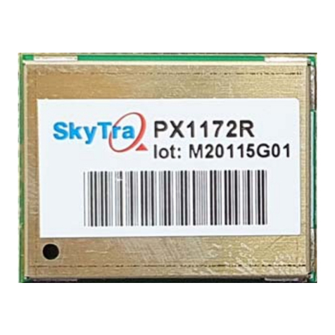
SkyTraq PX1172R-20 User manual

1
www.skytraq.com.tw
PX1172R‐20
Features
Decimeter‐levelaccuracyRTKreceiver
Multi‐Band,Quad‐GNSS
17mmx22mmsize
NMEA‐0183andRTCM3.xprotocol
Easytointegrate
Operatingtemperature‐40~+85ºC
RoHScompliant
Applications
HighAccuracyGuidance
GISdatacollection
LowCostRTKReceiverfor
Decimeter‐LevelAccuracy
PositioningApplications
ThePX1172R‐20offersdecimeter‐levelaccuracybasedoncarrier
phase RTK technique and can be used for a wide range of
high‐accuracypositioningapplications.Its17mmx22mmstamp
size makes it ideal for mobile precision positioning application
requiringcompactformfactor.
ThereceiverreceivesRTCM3.xdatafromalocalbasestation,a
virtualreferencestation(VRS)inaNetworkRTKconfiguration,
oranotherSkyTraqRTKreceiversetupasinbasestationmode
to perform carrier phase RTK processing, achieving decimeter
levelaccuraterelativepositioning.
The PX1172R‐20 receiver is based on SkyTraq’s
high‐performance Phoenix GNSS chipset, featuring fast signal
acquisition search engine and high‐sensitivity track engine.
Search engine performs 16 million time‐frequency hypothesis
testing per second, offering industry‐leading signal acquisition
performance.
Thereceiverisoptimizedformassmarketapplicationsrequiring
high‐precision decimeter‐level accuracy, high‐performance, low
power,andlowercost.

2
www.skytraq.com.tw
TECHNICALSPECIFICATIONS
ReceiverType 230channelPhoenixGNSSengine
GPSL1/L2C,BeiDouB1/B2,GalileoE1/E5b,GLONASSL1/L2,QZSSL1/ L 2 C
AccuracyPosition1.5mCEPautonomousmode
20cm+1ppmRTKmode
Velocity0.05m/sec*
1
Time12ns
TimetoFirstFix 1secondhot‐startunderopensky(average)
28secondwarm‐startunderopensky(average)
29secondcold‐startunderopensky(average)
RTKConvergence <10sec
Reacquisition 1s
MaxUpdateRate 1/2/4/5/8/10Hz
OperationalLimits Altitude<80,000mandvelocity<515m/s
SerialInterface 3.3VLVTTLlevel
ProtocolNMEA‐0183V4.1
GGA,GLL,GSA,GSV,RMC,VTG
115200baud,8,N,1
RTCM3.x
115200baud,8,N,1
DatumDefaultWGS‐84anduserdefinableinstand‐alonemode
DependsonbasereferenceframewheninRTKmode
InputVoltage 3.3VDC+/‐10%
CurrentConsumption 100mA
Dimension17mmLx22mmWx2.9mmH
Weight:1.7g
OperatingTemperature ‐40oC~+85oC
StorageTemperature ‐55oC~+100oC
Humidity5%~95%non‐condensing
*150%@30m/sfordynamicoperation

3
www.skytraq.com.tw
FUNCTIONALDESCRIPTION
ActiveantennaisrequiredtousewithPX1172R‐20.Thereceivedsignalgoesthroughasignal
splitter,toindividualL1andL2/L5SAWfilterstoremoveout‐bandinterference,thentothePX100
GNSSreceiverchipforRTKsignalprocessing.UsingcorrectiondatafromanRTKbasestation,the
roverPX1172R‐20computesitspositiontocentimeter‐levelaccuracyrelativetothebasestation.
SUPPORTEDRTCMMESSAGES
Whenoperatinginrovermode,PX1172R‐20candecodefollowingRTCM3.3messages:
RTCMMessageType Description
1004 ExtendedL1/L2GPSRTKobservables
1005 StationaryRTKreferencestationantennareferencepoint
1006 StationaryRTKreferencestationARPwithantennaheight
1012 ExtendedL1/L2GLONASSRTKobservables
1033 Receiverandantennadescription
1074 GPSMSM4
1075 GPSMSM5
1076 GPSMSM6
1077 GPSMSM7
1084 GLONASSMSM4
1085 GLONASSMSM5
1086 GLONASSMSM6
1087 GLONASSMSM7
1094 GalileoMSM4
1095 GalileoMSM5
1096 GalileoMSM6
1097 GalileoMSM7
1114
Q
ZSSMSM4
1115 QZSSMSM5
1116 QZSSMSM6

4
www.skytraq.com.tw
1117 QZSSMSM7
1124 BeiDouMSM4
1125 BeiDouMSM5
1126 BeiDouMSM6
1127 BeiDouMSM7
1230 GLONASSCode‐PhaseBiases

5
www.skytraq.com.tw
PINOUT
PINOUTDESCRIPTION
PinNo. Name Description
1
GND
Ground
2
RF_IN
RFinput
3
GND
Ground
4,5,6
NC
Noconnection,emptypin
7
VCC_RF
VoltageforexternalLNA
8,9,10,11
NC
Noconnection,emptypin
12
GND
Ground
13
NC
Noconnection,emptypin
14
GND
Ground
15,16,17,18,19
NC
Noconnection,emptypin

6
www.skytraq.com.tw
20
RTK_STAT
Status signal
0:RTKFix
Blink :RTKFloat
1:otherwise
21,22,23,24,25
NC
Noconnection,emptypin
26
RXD2
UARTserialdatainput,3.3VLVTTL.
OnesimplexasynchronousserialUARTportisimplemented.ThisUARTinputis
normallyforsendingRTCM‐SC104correctiondataorbasestationSkyTraqraw
measurementdatatothereceiverat115200 baudrate.Inthe idlecondition,
thispinshouldbedrivenHIGH.Ifthedrivingcircuitryispoweredindependently
ofPX1172R‐20,ensurethatthispinisnotdriventoHIGHwhenPX1172R‐20is
put to sleep, or a 10K‐ohm series resistor can be added to minimize leakage
current.
27
TXD2
UARTserialdataoutput,3.3VLVTTL.
Notused.
28,29,30,31
NC
Noconnection,emptypin
32
GND
Ground
33,34
VDD33
Powersupply,3.3VDC
35
NC
Noconnection,emptypin
36
V_BCKP
Backupsupply voltage for internalRTC andbackup SRAM,1.3V~ 3.6V. VBAT
must be applied whenever VCC is applied. This pin should be powered
continuously to minimize the startup time. If VCC and V_BCKP are both
removed,thereceiverwillbeinfactorydefaultmodeuponpowerup,alluser
configurationsetislost.Forapplicationsthedoesnotcarecoldstartingevery
time,thispincanbeconnecttoVCC.
37
GND
Ground
38,39,40
NC
Noconnection,emptypin
41
GND
Ground
42
TXD
UARTserialdataoutput,3.3VLVTTL.
One full‐duplex asynchronous serial UART port is implemented. This UART
output is normally used for sending position, time and velocityinformation
fromthereceiverinNMEA‐0183format.Whenidle,thispinoutputHIGH.
43
RXD
UARTserialdatainput,3.3VLVTTL.
Onefull‐duplexasynchronousserialUARTportisimplemented.ThisUARTinput
is normally for sending commands or information to the receiver in SkyTraq
binary protocol. In the idle condition, this pin should be driven HIGH. If the
drivingcircuitryispoweredindependentlyofPX1172R‐20,ensurethatthispin
is not driven to HIGH when PX1172R‐20 is put to sleep, or a 10K‐ohm series
resistorcanbeaddedtominimizeleakagecurrent.
RTCM‐SC104correctiondatacanalsobesenttothisUARTinput.
44
SDA
Notused,leaveunconnected
45
SCL
Notused,leaveunconnected
46,47
NC
Noconnection,emptypin
48
GND
Ground
49
RSTN
Externalactive‐lowresetinputto thebaseband.
Onlyneededwhenpowersupplyrisetimeisverysloworsoftwarecontrolled
resetisdesired.
50
BOOT_SEL
Noconnectionfornormaluse.Pull‐lowforloadingfirmwareintoemptyor
corruptedFlashmemoryfromROMmode.
51
TRIG
Externalinterrupttriggerinput
52
NC
Noconnection,emptypin

7
www.skytraq.com.tw
53
1PPS
One‐pulse‐per‐second (1PPS) time mark output, 3.3V LV‐TTL. The rising edge
synchronizedtoUTCsecondwhengetting3Dpositionfix.Thepulsedurationis
about100msecatrateof1Hz.
54
NC
Noconnection,emptypin
TheRTCMcorrectiondatacanbeinputfromeitherpin‐43RXDorpin‐26RXD2,butnotboth.

8
www.skytraq.com.tw
MECHANICALDIMENSION
Symbol Dimension(mm)
A 17.00
B 22.00
C 3.85
D 1.05
E 1.90
F 1.10
G 0.80
H 1.50
K 3.65
L 3.25
M 2.10
N 1.10

9
www.skytraq.com.tw
ELECTRICALSPECIFICATIONS
ABSOLUTEMAXIMUMRATINGS
Parameter Minimum Maximum Condition
SupplyVoltage(VCC) ‐0.5 3.6 Volt
BackupBatteryVoltage(V_BCKP) ‐0.5 3.6 Volt
InputPinVoltage ‐0.5 VCC+0.5 Volt
InputPoweratRF_IN +5 dBm
StorageTemperature ‐55 +100 degC
OPERATINGCONDITIONS
Parameter Min Typ Max Unit
SupplyVoltage(VDD33) 3 3.3 3.6 Volt
AcquisitionCurrent(excludeactiveantennacurrent) 100 mA
TrackingCurrent(excludeactiveantennacurrent) 100 mA
BackupVoltage(V_BCKP) 1.3 3.6 Volt
BackupCurrent(VDD33voltageapplied) 54 uA
BackupCurrent(VDD33voltageoff) 13 uA
OutputLowVoltage 0.4 Volt
OutputHIGHVoltage 2.4 Volt
InputLOWVoltage 0.8 Volt
InputHIGHVoltage 2 Volt
InputLOWCurrent ‐10 10 uA
InputHIGHCurrent ‐10 10 uA
RFInputImpedance(RF_IN) 50 Ohm

10
www.skytraq.com.tw
APPLICATIONCIRCUIT
ForPrecisePositioning,RoverModeConfiguration1

11
www.skytraq.com.tw
ForPrecisePositioning,RoverModeConfiguration2
RECOMMANDEDREFLOWPROFILE
Thereflowprofileshownaboveshouldnotbeexceeded,sinceexcessivetemperaturesortransporttimesduring
reflowcandamagethemodule.Coolingtemperaturefallrate:max3°C/sec

12
www.skytraq.com.tw
ANTENNACONSIDERATIONS
The PX1172R‐20 is designed to be used with GPS L1/L2C, GLONASS L1/L2, Beidou B1I/B2I, Galileo E1/E5b
multi‐frequency active antenna. Antenna with gain up to 40dB and noise figure less than 2dB can be used. It is
importanttoselectahigh‐performanceantennatoachieveoptimalRTKperformance.
POWERSUPPLYREQUIREMENT
PX1172R‐20 requires a stable power supply, avoid ripple on VCC pin (<50mVpp). Power supplynoise can affect the
receiver’ssensitivity.BypasscapacitorsshouldbeplacedclosetothemoduleVCCpin,withvaluesadjusteddepending
ontheamountandtypeofnoisepresentonthesupplyline.
BACKUPSUPPLY
The purpose of backup supply voltage pin (V_BCKP) is to keep the SRAM memory and the RTC powered when the
moduleispowereddown.Thisenablesthemoduletohaveafastertime‐to‐first‐fixwhenthemoduleispoweredon
again.Thebackupcurrentdrainislessthan55μA.Innormalpoweredonstate,theinternalprocessoraccesstheSRAM
andcurrentdrainishigherinactivemode
1PPSOUTPUT
A1pulsepersecondsignal(100msecHIGHduration)isgeneratedon1PPSpinwhenthereceiverhas3Dpositionfix
using4ormoresatellites.TherisingedgeofthepulseisalignedwithUTCsecond,withaccuracyofabout10nsec.It
outputsconstantLOWwhennopositionfixisavailableinitially.
LAYOUTGUIDELINES
SeparateRFanddigitalcircuitsintodifferentPCBregions.
Itisnecessarytomaintain50‐ohmimpedancethroughouttheentireRFsignalpath.TrykeepingtheRFsignalpathas
shortaspossible.
DonotroutetheRFsignallinenearnoisysourcessuchasdigitalsignals,oscillators,switchingpowersupplies,orother
RF transmitting circuit. Do not route the RF signal under or over any other components (includingPX1172R‐20), or
othersignaltraces.DonotroutetheRFsignalpathonaninnerlayerofamulti‐layerPCBtominimizesignalloss.
AvoidsharpbendsforRFsignalpath.Maketwo45‐degbendsoracircularbendinsteadofasingle90‐degreebendif
needed.
Avoid vias with RF signal path whenever possible. Every via addsinductiveimpedance.Viasareacceptablefor
connectingtheRFgroundsbetweendifferentlayers.Eachofthemodule’sgroundpinsshouldhaveshorttracetying
immediatelytothegroundplanebelowthroughavia.
ThebypasscapacitorsshouldbelowESRceramictypesandlocateddirectlyadjacenttothepintheyarefor.

13
www.skytraq.com.tw
HANDLINGGUIDELINE
ThePX1172R‐20modulesareratedMSL4,mustbeusedforSMTreflowmountingwithin72hoursaftertakenoutfrom
the vacuumed ESD‐protective moisture barrier bag in factory condition < 30degC / 60% RH. If this floor life time is
exceeded,orifthereceivedESD‐protectivemoisturebarrierbagisnotinvacuumedstate,thenthedeviceneedtobe
pre‐bakedbeforeSMTreflowprocess.Bakingistobedoneat85degCfor8to12hours.Oncebaked,floorlifecounting
beginsfrom0,andhas72hoursoffloorlifeatfactorycondition<30degC/60%RH.
PX1172R‐20moduleisESDsensitivedeviceandshouldbehandledwithcare.
RTKUsageGuideline
BelowconditionsarerequiredforgettingRTKfixsolution.Iftheconditionsarenotmet,PX1172R‐20willonlyhave
floatorDGPS/3DsolutionandbehavelikeanormalGNSSreceiver.
*Openskyenvironmentwithoutinterference
*Signalover37dB/Hz
*14ormoresatellitesabove15degreeelevationanglewithgoodsatellitegeometryorlowDOPvalue;generallymore
satelliteswillhavefasterRTKfix

14
www.skytraq.com.tw
NMEAOutputDescription
TheoutputprotocolsupportsNMEA‐0183standard.TheimplementedmessagesincludeGGA,GLL,GSA,GSV,VTG,
RMC,ZDAandGNSmessages.TheNMEAmessageoutputhasthefollowingsentencestructure:
$aaccc,c–c*hh<CR><LF>
ThedetailofthesentencestructureisexplainedinTable1.
Table1:TheNMEAsentencestructure
character HEX Description
“$” 24 Startofsentence.
Aaccc Addressfield.“aa”isthetalkeridentifier.“ccc”identifiesthesentencetype.
“,” 2C Fielddelimiter.
C
–
c Datasentenceblock.
“*” 2A Checksumdelimiter.
Hh Checksumfield.
<CR><LF> 0D0A Endingofsentence.(carriagereturn,linefeed)
Table2:OverviewofSkyTraqreceiver’sNMEAmessages
$GPGGA Time,position,andfixrelateddataofthereceiver.
$GNGLL Position,timeandfixstatus.
$GNGSA UsedtorepresenttheID’sofsatelliteswhichareusedforpositionfix.WhenGPSsatellitesareusedfor
positionfix,$GNGSAsentenceisoutputwithsystemID1.WhenGLONASSsatellitesareusedfor
positionfix,$GNGSAsentenceisoutputwithsystemID2.WhenGalileosatellitesareusedforposition
fix,$GNGSAsentenceisoutputwithsystemID3.WhenBDSsatellitesareusedforpositionfix,
$GNGSAsentenceisoutputwithsystemID4.
$GPGSV
$GLGSV
$GAGSV
$GBGSV
Satelliteinformationaboutelevation,azimuthandCNR,$GPGSVisusedforGPSsatellites,$GLGSVis
usedforGLONASSsatellites,$GAGSVisusedforGALILEOsatellites,while$GBGSVisusedforBDS
satellites
$GNRMC Time,date,position,courseandspeeddata.
$GNVTG Courseandspeedrelativetotheground.
$GNZDA UTC,day,monthandyearandtimezone.
$GNTHS TrueHeadingandStatus.

15
www.skytraq.com.tw
TheformatsofthesupportedNMEAmessagesaredescribedasfollows:
GGA–GlobalPositioningSystemFixData
Time,positionandfixrelateddataforaGPSreceiver.
Structure:
$GPGGA,hhmmss.sss,ddmm.mmmmmmm,a,dddmm.mmmmmmm,a,x,xx,x.x,x.x,M,x.x,M,x.x,xxxx*hh<CR><LF>
123456789101112
Example:
$GPGGA,033010.000,2447.0895508,N,12100.5234656,E,4,12,0.7,94.615,M,19.600,M,,0000*66<CR><LF>
Field Name Example Description
1 UTCTime 033010.000 UTCofpositioninhhmmss.sssformat,(000000.000~235959.999)
2 Latitude 2447.0895508 Latitudeinddmm.mmmmmmmformat
Leadingzerostransmitted
3 N/SIndicator N Latitudehemisphereindicator,‘N’=North,‘S’=South
4 Longitude 12100.5234656 Longitudeindddmm.mmmmmmmformat
Leadingzerostransmitted
5 E/WIndicator E Longitudehemisphereindicator,‘E’ =East,‘W’=West
6 GPSquality
indicator
4 GPSqualityindicator
0:positionfixunavailable
1:validpositionfix,SPSmode
2:validpositionfix,differentialGPSmode
3:GPSPPSMode,fixvalid
4:RealTimeKinematic.SystemusedinRTKmodewithfixedintegers
5:FloatRTK.SatellitesystemusedinRTKmode.,floatingintegers
6:Estimated(deadreckoning)Mode
7:ManualInputMode
8:SimulatorMode
7 SatellitesUsed 12 Numberofsatellitesinuse,(00~12)
8 HDOP 0.7 Horizontaldilutionofprecision,(0.0~99.9)
9 Altitude 94.615 meansealevel(geoid),(‐9999.9~17999.9)
10 GeoidalSeparation 19.600 Geoidalseparationinmeters
11 AgepfDifferential
GPSdata
AgeofDifferentialGPSdata
NULLwhenDGPSnotused
12 DGPSStationID 0000 DifferentialreferencestationID,0000~1023
13 Checksum 66

16
www.skytraq.com.tw
GLL–Latitude/Longitude
Latitudeandlongitudeofcurrentposition,time,andstatus.
Structure:
$GNGLL,ddmm.mmmmmmm,a,dddmm.mmmmmmm,a,hhmmss.sss,A,a*hh<CR><LF>
12345678
Example:
$GNGLL,2447.0895508,N,12100.5234656,E,033010.000,A,D*48<CR><LF>
Field Name Example Description
1 Latitude 2447.0895508 Latitudeinddmm.mmmmmmmformat
Leadingzerostransmitted
2 N/SIndicator N Latitudehemisphereindicator
‘N’=North
‘S’=South
3 Longitude 12100.5234656 Longitudeindddmm.mmmmmmmformat
Leadingzerostransmitted
4 E/WIndicator E Longitudehemisphereindicator
‘E’=East
‘W’=West
5 UTCTime 033010.000 UTCtimeinhhmmss.sssformat(000000.000~235959.999)
6 Status A Status,‘A’=Datavalid,‘V’=Datanotvalid
7 ModeIndicator D Modeindicator
‘A’=Autonomousmode
‘D’=Differentialmode
‘E’=Estimated(deadreckoning)mode
‘M’=Manualinputmode
‘S’=Simulatormode
‘N’=Datanotvalid
8 Checksum 48

17
www.skytraq.com.tw
GSA–GNSSDOPandActiveSatellites
GNSSreceiveroperatingmode,satellitesusedinthenavigationsolutionreportedbytheGGAorGNSsentenceand
DOPvalues.
Structure:
$GNGSA,A,x,xx,xx,xx,xx,xx,xx,xx,xx,xx,xx,xx,xx,x.x,x.x,x.x,x*hh<CR><LF>
1233333333333345678
Example:
$GNGSA,A,3,05,12,13,15,20,21,24,193,,,,,1.2,0.7,1.0,1*08<CR><LF>
$GNGSA,A,3,01,03,04,06,07,13,16,21,26,,,,1.2,0.7,1.0,4*34<CR><LF>
Field Name Example Description
1 Mode A Mode
‘M’=Manual,forcedtooperatein2Dor3Dmode
‘A’=Automatic,allowedtoautomaticallyswitch2D/3D
2 Mode 3 Fixtype
1=Fixnotavailable
2=2D
3=3D
3 Satelliteused1~12 05,12,13,15,20,2
1,24,193
01~ 32areforGPS;33 ~ 64areforWAAS(PRNminus87);193
~197areforQZSS;65~88areforGLONASS(GLPRN);01~36
areforGALILEO(GAPRN);01~37areforBDS(BDPRN).GPS,
GLONASS,GALILEOandBDSsatellitesaredifferentiatedbythe
GNSSsystemIDintable3.Maximally12satellitesareincluded
ineachGSAsentence.
4 PDOP 1.2 Positiondilutionofprecision(0.0to99.9)
5 HDOP 0.7 Horizontaldilutionofprecision(0.0to99.9)
6 VDOP 1.0 Verticaldilutionofprecision(0.0to99.9)
7 GNSSSystemID 1 GNSSsystemID*
1=GPS
2=GLONASS
3=GALILEO
4=BDS
5=IRNSS
8 Checksum 08
*GNSSSystemIDidentifiestheGNSSsystemIDaccordingtoTable3.

18
www.skytraq.com.tw
*GNSSSignalIDidentifiestheGNSSsignalnameaccordingtoTable3.
Table3:GNSSIdentificationTableforGSA,GSV
System SystemID(Talker) SignalID SignalName
GPS 1(GP) 0
1
2
3
4
5
6
7
8
Allsignals
L1C/A
L1 P(Y)
L1C
L2 P(Y)
L2C‐M
L2C‐L
L5‐I
L5‐Q
GLONASS 2(GL) 0
1
2
3
4
All signals
G1 C/A
G1P
G2 C/A
GLONASS (M) G2P
GALILEO 3(GA) 0
1
2
3
4
5
6
7
All signals
E5a
E5b
E5 a+b
E6‐A
E6‐BC
L1‐A
L1‐BC
BDS 4(BD) 0
1
5
B
8
3
All signals
B1
B2A
B2
B3
B1C
IRNSS 5(GI) 0
4
All signals
L5

19
www.skytraq.com.tw
GSV–GNSSSatellitesinView
Numberofsatellites(SV)inview,satelliteIDnumbers,elevation,azimuth,andSNRvalue.Foursatellitesmaximumper
transmission.
Structure:
$GPGSV,x,x,xx,xx,xx,xxx,xx,…,xx,xx,xxx,xx,x*hh<CR><LF>
1234567456789
Example:
$GPGSV,3,1,10,24,83,125,48,193,66,057,44,21,53,277,45,15,43,034,47,1*58<CR><LF>
$GPGSV,3,2,10,20,40,325,43,05,16,113,40,13,15,050,39,12,14,146,42,1*6E<CR><LF>
$GPGSV,3,3,10,10,13,314,,32,06,261,,1*62<CR><LF>
$GPGSV,2,1,05,24,83,125,49,193,66,057,44,15,43,034,45,05,16,113,36,6*5B<CR><LF>
$GPGSV,2,2,05,12,14,146,37,6*57<CR><LF>
$GBGSV,3,1,09,13,65,247,45,06,60,334,43,03,59,204,41,26,58,153,47,1*7E<CR><LF>
$GBGSV,3,2,09,16,57,325,45,01,53,142,42,21,52,046,47,04,38,118,,1*7A<CR><LF>
$GBGSV,3,3,09,07,20,169,37,1*40<CR><LF>
$GBGSV,2,1,07,13,65,247,47,06,60,334,47,03,59,204,47,16,57,325,47,3*7C<CR><LF>
$GBGSV,2,2,07,01,53,142,49,04,38,118,45,07,20,169,43,3*44<CR><LF>
Field Name Example Description
1 Numberofmessage 3 TotalnumberofGSV messagestobetransmitted(1‐5)
2 Sequencenumber 1 SequencenumberofcurrentGSVmessage
3 Satellitesinview 10 Totalnumberofsatellitesinview (00~20)
4 SatelliteID 24 01~ 32areforGPS;33 ~ 64areforWAAS(PRNminus87);193
~197areforQZSS;65~88areforGLONASS(GLPRN);01~36
areforGALILEO(GAPRN);01~37areforBDS(BDPRN).GPS,
GLONASS,GALILEOandBDSsatellitesaredifferentiatedbythe
GNSSsystemIDintable3.Maximally4satellitesareincludedin
eachGSVsentence.
5 Elevation 83 Satelliteelevationindegrees,(00~90)
6 Azimuth 125 Satelliteazimuthangleindegrees,(000~359)
7 SNR 48 C/NoindB(00~99)
Nullwhennottracking
8 SignalID 1 SignalID*
9 Checksum 58

20
www.skytraq.com.tw
RMC–RecommendedMinimumSpecificGNSSData
Time,date,position,courseandspeeddataprovidedbyaGNSSnavigationreceiver.
Structure:
$GPRMC,hhmmss.sss,A,dddmm.mmmmmmm,a,dddmm.mmmmmmm,a,x.x,x.x,ddmmyy,,,a,a*hh<CR><LF>
123456789101112
Example:
$GNRMC,033010.000,A,2447.0895508,N,12100.5234656,E,000.0,000.0,111219,,,R,V*18<CR><LF>
Field Name Example Description
1 UTCtime 033010.000 UTCtimeinhhmmss.sssformat(000000.00~235959.999)
2 Status A Status
‘V’=Navigationreceiverwarning
‘A’=DataValid
3 Latitude 2447.0895508 Latitudeindddmm.mmmmmmmformat
Leadingzerostransmitted
4 N/Sindicator N Latitudehemisphereindicator
‘N’=North
‘S’=South
5 Longitude 12100.5234656 Longitudeindddmm.mmmmmmmformat
Leadingzerostransmitted
6 E/WIndicator E Longitudehemisphereindicator
‘E’=East
‘W’=West
7 Speedoverground 000.0 Speedovergroundinknots(000.0~999.9)
8 Courseoverground 000.0 Courseovergroundindegrees(000.0~359.9)
9 UTCDate 111219 UTCdateofpositionfix,ddmmyyformat
10 Modeindicator R Modeindicator
‘A’=Autonomousmode
‘D’=Differentialmode
‘E’=Estimated(deadreckoning)mode
‘F’=FloatRTK.SatellitesystemusedinRTKmode,floating
integers
‘M’=ManualInputMode
‘N’=Datanotvalid
‘P’=Precise
‘R’=RealTimeKinematic.SystemusedinRTKmodewithfixed
integers
‘S’=SimulatorMode
11 Navigationstatus V NavigationstatusindicatoraccordingtoIEC61108requirement
on‘Navigational(orFailure)warningsandstatusindicators’.
‘S’=Safe
‘C’=Caution
‘U’=Unsafe
‘V’=Navigationstatusnotvalid,equipmentisnotproviding
navigationstatusindicator.
12 checksum 18
Table of contents
Other SkyTraq Receiver manuals
